1
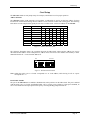
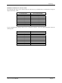
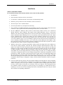
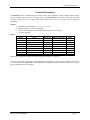
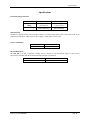
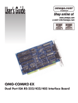
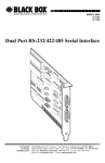
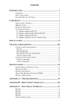
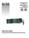
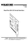
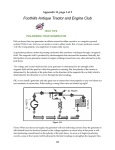
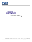
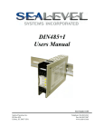
SIO-104
Users Manual
Part Number 3551
Sealevel Systems, Inc.
155 Technology Place
Liberty, SC 29657 USA
Telephone: 864.843.4343
Fax: 864.843.3067
www.sealevel.com
Contents
INTRODUCTION .................................................................................................................................................... 1
OVERVIEW .............................................................................................................................................. 1
WHAT’S INCLUDED ................................................................................................................................. 1
OPTIONAL ACCESSORIES ......................................................................................................................... 1
CARD SETUP ......................................................................................................................................................... 2
ADDRESS SELECTION .............................................................................................................................. 2
PORT ENABLE / DISABLE ......................................................................................................................... 2
IRQ SELECTION ...................................................................................................................................... 3
CLOCK MODES ........................................................................................................................................ 3
BAUD RATES AND DIVISORS FOR THE ‘DIV1’ MODE................................................................................ 4
INSTALLATION ..................................................................................................................................................... 5
WINDOWS 95/98/ME/NT/2000/XP......................................................................................................... 5
LINUX ..................................................................................................................................................... 6
QNX ....................................................................................................................................................... 6
PHYSICAL INSTALLATION ........................................................................................................................ 6
TECHNICAL DESCRIPTION ................................................................................................................................... 7
FEATURES ............................................................................................................................................... 7
RS-232................................................................................................................................................. 7
SPECIFICATIONS................................................................................................................................................... 8
ENVIRONMENTAL SPECIFICATIONS ......................................................................................................... 8
MANUFACTURING ................................................................................................................................... 8
POWER CONSUMPTION ............................................................................................................................ 8
PHYSICAL DIMENSIONS ........................................................................................................................... 8
APPENDIX A - TROUBLESHOOTING ..................................................................................................................... 9
APPENDIX B - HOW TO GET ASSISTANCE ......................................................................................................... 10
APPENDIX C - ELECTRICAL INTERFACE ........................................................................................................... 11
RS-232 ................................................................................................................................................. 11
APPENDIX D - PC/104 ........................................................................................................................................ 12
WHAT IS PC/104? ................................................................................................................................. 12
APPENDIX E - SILK-SCREEN .............................................................................................................................. 13
WARRANTY ........................................................................................................................................................ 14
© Revision February 19, 2004
Sealevel Systems, Incorporated. All rights reserved.
Introduction
Introduction
Overview
The SIO-104 is the ultimate single port RS-232 serial connection for your PC/104 application. The SIO-104 utilizes
the Exar 16C850, which provides 128-byte, transmit and receive FIFOs. These larger buffers allow error free
operation even in high-speed applications.
What’s Included
The SIO-I04 is shipped with the following items. If any of these items are missing or damaged, contact the
supplier.
•
•
•
(1) SIO-104 Serial Interface Adapter
(1) Nylon Mounting Hardware Kit (PC304-NK)
Sealevel SeaCOM Software CD
Optional Accessories
•
CA-152 - Terminates the ULTRA SIO-104 10 pin header to a DB9M connector. This cable provides
the standard DB9 pin out for RS-232 (aka EIA/TIA574).
Sealevel Systems SIO-104
Page 1
Card Setup
Card Setup
The SIO-104 contains several jumper straps for each port, which must be set for proper operation.
Address Selection
The SIO-104 occupies eight consecutive I/O locations. A DIP-switch is used to set the base address for these
locations. Be careful when selecting the base address as some selections conflict with existing ports. The following
table shows several examples that typically do not cause a conflict. SW1 sets the I/O address for the SIO-104.
Address
Hex
280-287
2A0-2A7
2E8-2EF
2F8-2FF
3E8-3EF
300-307
328-32F
3F8-3FF
Binary
A9
A0
1010000XXX
1010100XXX
1011101XXX
1011111XXX
1111101XXX
1100000XXX
1100101XXX
1111111XXX
Switch Position Setting
2
3
4
5
6
On Off On On On
On Off On Off On
On Off Off Off On
On Off Off Off Off
Off Off Off Off On
Off On On On On
Off On On Off On
Off Off Off Off Off
1
Off
Off
Off
Off
Off
Off
Off
Off
7
On
On
Off
Off
Off
On
Off
Off
Figure 1 - Address Selection Table
The following illustration shows the correlation between the DIP-switch setting and the address bits used to
determine the base address. In the example below, address 300 is selected as a base. Address 300 in binary is XX11
0000 0XXX where X = a non-selectable address bit.
A9
ON
1
A3 EN
2
3
4
5
6
7
8
Figure 2 - DIP-Switch Illustration
Note: Setting the switch “On” or “Closed” corresponds to a “0” in the address, while leaving it “Off” or “Open”
corresponds to a “1”.
Port Enable / Disable
The port on the SIO-104 can be enabled or disabled with switch position 8 on the DIP-switch. The port is enabled
with the switch “On” or “Closed” and disabled when “Off” or “Open” (refer to Figure 2). If the port is disabled, be
sure to also disable the interrupt request for that port by removing the IRQ jumper at header J2.
Sealevel Systems SIO-104
Page 2
Card Setup
IRQ Selection
The SIO-104 has an interrupt selection jumper, which should be set prior to use, if an interrupt is required by your
application software. Consult the user manual for the application software being used to determine the proper
setting. Position “R” is provided so that a jumper can be installed that connects a 1K-Ohm pull-down resistor to the
output of a high-impedance tri-state driver which carries the IRQ signal. Because the IRQ line is driven low only by
the pull-down resistor, it is possible for two or more boards to share the same IRQ signal. Position “R” installed is
the default setting and should be left as is unless multiple cards are sharing a single IRQ. If multiple adapters are
sharing a single IRQ, then only one adapter should have the pull-down resistor (position “R” selected) in the circuit.
2/9
3
4
5
7
10
11
12
15
R
The IRQ can be set at jumper J2 for IRQ 2/9, 3-5, 7, 10, 11, 12, or 15. In the following example, the IRQ is set as
IRQ4.
Figure 3 - Header J2, IRQ Selection (Factory Default)
Clock Modes
The ULTRA 530.PCI employs a unique clocking option that allows the end user to select from divide by 4 and
divide by 1 clocking modes. These modes are selected at Header E8.
DIV1
DIV4
To select the Baud rates commonly associated with COM: ports (i.e. 2400, 4800, 9600, 19.2, … 115.2K Bps ) place
the jumper in the divide by 4 mode (silk-screen DIV4).
Figure 4 - Clocking Mode ‘Divide By 4’
DIV1
DIV4
To select the maximum data rate (460.8K bps) place the jumper in the divide by 1 (silk-screen DIV1) position.
Figure 5 - Clocking Mode ‘Divide By 1’
Sealevel Systems SIO-104
Page 3
Card Setup
Baud Rates and Divisors for the ‘Div1’ mode
The following table shows some common data rates and the rates you should choose to match them if using the
adapter in the ‘Div1’ mode.
For this Data Rate
1200 bps
2400 bps
4800 bps
9600 bps
19.2K bps
57.6 K bps
115.2 K bps
230.4K bps
460.8K bps
Choose this Data Rate
300 bps
600 bps
1200 bps
2400 bps
4800 bps
14.4K bps
28.8K bps
57.6 K bps
115.2 K bps
If your communications package allows the use of Baud rate divisors, choose the appropriate divisor from the
following table:
For this Data Rate
1200 bps
2400 bps
4800 bps
9600 bps
19.2K bps
38.4K bps
57.6K bps
115.2K bps
230.4K bps
460.8K bps
Sealevel Systems SIO-104
Choose this Divisor
384
192
96
48
24
12
8
4
2
1
Page 4
Installation
Installation
Windows 95/98/ME/NT/2000/XP
Do not install the adapter in the machine until the software has been fully installed.
1.
Start Windows.
2.
Insert the Sealevel Systems CD in to your CD drive.
3.
If ‘Auto-Start’ is enabled for this drive the software will automatically launch.
4.
Otherwise, point your browser to the ‘Index.htm’ on the root of the CD
5.
The next step is to select ‘Install Software’.
6.
Select the part number for your adapter from the listing.
7.
Select ‘Windows 95/98/ME/NT/2000/XP’ then (depending on the OS version) select the ‘Run from current
Location’ or ‘Open’ option. Follow the information presented on the screens that follow.
8.
Run the Add/Remove Hardware utility located in Control Panel. Double click the icon to launch the
Wizard. When the Choose Hardware Task appears choose Add/Troubleshoot a device. At that point
Windows will search for Plug and Play devices. Since the ISA board is not Plug and Play it will not be
found. If Windows finds something you were not expecting, cancel that install and click Next. When
Choose a Hardware Device appears select Add a new device. Windows will then ask if you want it to
search and you select No, I want to select the hardware from a list. Then click Next. After choosing Next
you will see Hardware Type. If you are installing a single port serial card select Ports (COM & LPT). If
you are installing a multiport serial card, ( two or more ports), choose Multi-port serial adapters. Click
Next. The Select a Device Driver window will appear. On the left side find Sealevel Systems, Inc. and on
the right side of the window select the card type you are installing
9.
Windows will now show a warning message that it could not detect the settings of the device and that you
must enter the settings manually. Click OK. The Add New Hardware Wizard Properties window will
appear. This window will show the default settings for the I/O address and one IRQ. The one IRQ will
mean that you will be sharing one IRQ for all ports on the board for a multi port card. You will only need
one IRQ if installing a single port card. Since Windows cannot detect the settings there my be a conflict
with another device or the settings shown may be not the settings you wish to use. To change the settings
choose Basic configuration 0001 next to the heading Setting based on:. When this configuration is chosen
the Resources window will appear with all question marks. Simply choose each Input/Output Range and
IRQ and change the settings to match the board settings. Make sure there are no conflicts with other
devices that would appear at the bottom of the window under Conflicting device list. After you have either
accepted the default settings or changed the settings, the Start Hardware Installation window will appear.
Click Next.
10. The next window that may appear will be the Digital Signature Not Found. Do not search for digitally
signed software and continue with the installation. The Completing the Add/Remove Hardware Wizard
window will appear. You will be given a chance to change the resource settings again at this point if
necessary. Choose Finish. At this point you will need to restart your computer. After restarting the Found
New Hardware window will appear for each port that you are installing. To confirm that the drivers
installed you can now look in Device Manager under Ports (COM &LPT) and each of the ports should
show with their corresponding COM number.
Sealevel Systems SIO-104
Page 5
Installation
Linux
Refer to D:\software\seacom\Other\Linux\Linux.serial.readme (where D: = your CDROM driver letter) found on
the Sealevel Systems CD. This file contains valuable information on installing your adapter in the various Linux
releases. Also in this sub-directory is the Linux SerialHOWTO. This series of files explains typical Linux serial
implementations, as well as informing the user to Linux syntax and preferred practices.
QNX
Refer to D:\software\seacom\Other\QNX6\Install.readme (where D: = your CDROM driver letter) found on the
Sealevel Systems CD. This file contains valuable information on installing your adapter in the QNX6 Neutrino OS,
as well as the files required to ensure a flawless implementation. Also provided on the Sealevel Systems CD are
implementation instructions for QNX4. These are found in D:\software\seacom\Other\QNX4\QNX_COM.txt.
Physical Installation
Extreme care should be taken when installing the SIO-104 to avoid causing damage to the connectors. After the
adapter is installed, connect your I/O cable to J1. Please note these headers are keyed so that pin 1 of the cable
matches pin 1 of the connector. Refer to Card Setup for information on setting the address and jumper options
before inserting the SIO-104 onto the stack.
1.
Turn off PC power. Disconnect the power cord.
2.
Remove the case cover (if applicable).
3.
Gently insert the SIO-104 into the connector noting proper key orientation of the expansion connector on a
PC/104 compatible card. The SIO-104 adapter is keyed per the current PC/104 Specification. This will aid
in preventing the adapter from being inserted incorrectly.
4.
Mounting hardware (nylon stand-offs and screws) is provided to ensure a good mechanical connection.
Retain any mounting hardware not used to allow for future expansion.
5.
The cables provided are keyed and can be installed before or after the adapter is inserted in the stack.
6.
Replace the cover.
7.
Connect the power cord and power up the machine.
Installation is complete.
Sealevel Systems SIO-104
Page 6
Technical Description
Technical Description
The SIO-104 provides a standard RS-232C interface that is fully compatible with all popular modem software,
network operating systems software, and mouse drivers. The SIO-104 utilizes the Exar 16C850, which provides
128-byte, transmit and receive FIFOs. These larger buffers allow error free operation even in high-speed
applications.
Features
•
•
•
•
Selectable interrupts (IRQs) 3, 4, 5, 7, 9, 10, 11, 12, 15
Multiple adapters can share the same IRQ
Uses PC/104 compatible stack through connector for universal mounting
5 volt DC operation
RS-232
Signal
Name
Header J1
DB9 (CA152) Pin #
GND
Ground
9
5
TD
Transmit Data
5
3
RTS
Request To Send
4
7
DTR
Data Terminal Ready
7
4
RD
Receive Data
3
2
CTS
Clear To Send
6
8
DSR
Data Set Ready
2
6
CD
Carrier Detect
1
1
RI
Ring Indicator
8
9
Note: These assignments meet EIA/TIA/ANSI-574 DTE for DB-9 type connectors.
Mode
Output
Output
Output
Input
Input
Input
Input
Input
Technical Note: Please terminate any control signals that are not going to be used. The most common way to do this
is connect RTS to CTS and RI, DTR to DCD and DSR. Terminating these pins, if not used, will help insure you get
the best performance from your adapter.
Sealevel Systems SIO-104
Page 7
Specifications
Specifications
Environmental Specifications
Specification
Temperature
Range
Humidity Range
Operating
0º to 70º C
(32º to 158º F)
10 to 90% R.H.
Non-Condensing
Storage
-50º to 105º C
(-58º to 221º F)
10 to 90% R.H.
Non-Condensing
Manufacturing
All Sealevel Systems Printed Circuit boards are built to UL 94V0 rating and are 100% electrically tested. These
printed circuit boards are solder mask over bare copper or solder mask over tin nickel.
Power Consumption
Supply Line
+5 VDC
Rating (mA)
125 mA
Physical Dimensions
The SIO-104 is PC/104 “Compliant” meaning that it conforms to all non-optional aspects of the PC/104
Specification, including both the mechanical and the electrical specifications.
Board Length
Board Width
Sealevel Systems SIO-104
3.775 inches
3.550 inches
(9.588 cm)
(9.017 cm)
Page 8
Appendix A - Troubleshooting
Appendix A - Troubleshooting
Sealevel Software is supplied with the Sealevel Systems adapter and may be used in the troubleshooting procedures.
Using this software and following these simple steps can eliminate most common problems without the need to call
Technical Support.
1.
Identify all I/O adapters currently installed in your system. This includes your on-board serial ports, controller
cards, sound cards etc. The I/O addresses used by these adapters, as well as the IRQ (if any) should be
identified.
2.
Configure your Sealevel Systems adapter so that there is no conflict with currently installed adapters. No two
adapters can occupy the same I/O address.
3.
Make sure the Sealevel Systems adapter is using a unique IRQ. While the Sealevel Systems adapter does allow
the sharing of IRQs, many other adapters (i.e. SCSI adapters & on-board serial ports) do not..
4.
When running DOS or Windows 3.x refer to the supplied Sealevel Software and this User Manual to verify that
the Sealevel Systems adapter is configured correctly. This software contains a diagnostic program ‘SSD’
(D:\software\seacom\Other\DOS\DIAG, where D: = the driver letter of your CDROM drive) will verify if an
adapter is configured properly. This diagnostic program is written with the user in mind and is easy to use.
5.
For Windows95/98/ME/NT/2000, the diagnostic tool ‘WinSSD’ is installed in the SeaCOM folder on the Start
Menu during the setup process. First find the ports using the Device Manager, then use ‘WinSSD’ to verify that
the ports are functional.
6.
Always use the Sealevel Systems diagnostic software when troubleshooting a problem. This will eliminate any
software issues from the equation.
Sealevel Systems SIO-104
Page 9
Appendix B - How To Get Assistance
Appendix B - How To Get Assistance
Please refer to Troubleshooting Guide prior to calling Technical Support.
1.
Begin by reading through the Trouble Shooting Guide in Appendix A. If assistance is still needed
please see below.
2.
When calling for technical assistance, please have your user manual and current adapter settings. If
possible, please have the adapter installed in a computer ready to run diagnostics.
3.
Sealevel Systems provides an FAQ section on its web site. Please refer to this to answer many
common questions. This section can be found at http://www.sealevel.com/faq.asp.
4.
Sealevel Systems maintains a web page on the Internet. Our home page address is
http://www.sealevel.com. The latest software updates, and newest manuals are available via our web
site.
5.
Technical support is available Monday to Friday from 8:00 a.m. to 5:00 p.m. eastern time. Technical
support can be reached at (864) 843-4343.
Return Authorization Must Be Obtained From Sealevel Systems Before Returned Merchandise Will Be
Accepted. Authorization Can Be Obtained By Calling Sealevel Systems And Requesting A Return
Merchandise Authorization (RMA) Number.
Sealevel Systems SIO-104
Page 10
Appendix C - Electrical Interface
Appendix C - Electrical Interface
RS-232
Quite possibly the most widely used communication standard is RS-232. This implementation has been defined and
revised several times and is often referred to as RS-232-C/D/E or EIA/TIA-232-C/D/E. It is defined as “Interface
between Data Terminal Equipment and Data Circuit- Terminating Equipment Employing Serial Binary Data
Interchange”. The mechanical implementation of RS-232 is on a 25-pin D sub connector. The IBM PC computer
defined the RS-232 port on a 9 pin D sub connector and subsequently the EIA/TIA approved this implementation as
the EIA/TIA-574 standard. This standard has defined as the “9-Position Non-Synchronous Interface between Data
Terminal Equipment and Data Circuit-Terminating Equipment Employing Serial Binary Data Interchange”. Both
implementations are in wide spread use and will be referred to as RS-232 in this document. RS-232 is capable of
operating at data rates up to 20K bps / 50 ft. The absolute maximum data rate may vary due to line conditions and
cable lengths. RS-232 often operates at 38.4K bps over very short distances. The voltage levels defined by RS-232
range from -12 to +12 volts. RS-232 is a single ended or unbalanced interface, meaning that a single electrical
signal is compared to a common signal (ground) to determine binary logic states. A voltage of +12 volts (usually +3
to +10 volts) represents a binary 0 (space) and -12 volts (-3 to -10 volts) denote a binary 1 (mark). The RS-232 and
the EIA/TIA-574 specification define two types of interface circuits Data Terminal Equipment (DTE) and Data
Circuit-Terminating Equipment (DCE). The Sealevel Systems Adapter is a DTE interface.
Sealevel Systems SIO-104
Page 11
Appendix D - PC/104
Appendix D - PC/104
What is PC/104?
The PC has become extremely popular in both general purpose (desktop) and dedicated (embedded) applications.
Unfortunately the PC has been hampered by the large size required to maintain PC compatibility. PC/104 addresses
this by optimizing the PC bus in a form factor designed for embedded applications.
Briefly, the key differences between PC/104 and the standard “AT” or ISA bus computer are as follows:
•
Reducing the form factor, to 3.550 by 3.775 inches
•
Eliminating the need for backplanes or card cages, through its self-stacking bus
•
Minimizing component count and power consumption (typically 1-2 Watts per module) by reducing required
bus drive on most signals to 4 mA.
Sealevel Systems has been a member of the PC/104 Consortium since its inception.
Questions about the PC/104 Consortium can be sent to:
PC/104 Consortium
P. O. Box 4303
Mountain View, CA 94040
(415) 903-8304 Ph. (415) 967-0995 Fax
www.controlled.com/pc104
Sealevel Systems SIO-104
Page 12
Appendix E - Silk-Screen
Appendix E - Silk-Screen
Sealevel Systems SIO-104
Page 13
Warranty
Warranty
Sealevel's commitment to providing the best I/O solutions is reflected in the Lifetime
Warranty that is standard on all Sealevel manufactured products. We are able to offer
this warranty due to our control of manufacturing quality and the historically high
reliability of our products in the field. Sealevel products are designed and
manufactured at its Liberty, South Carolina facility, allowing direct control over
product development, production, burn-in and testing.
Sealevel Systems, Inc. (hereafter "Sealevel") warrants that the Product shall conform to and perform in accordance
with published technical specifications and shall be free of defects in materials and workmanship for life. In the
event of failure, Sealevel will repair or replace the product at Sealevel's sole discretion. Failures resulting from
misapplication or misuse of the Product, failure to adhere to any specifications or instructions, or failure resulting
from neglect or abuse are not covered under this warranty.
Warranty service is obtained by delivering the Product to Sealevel and providing proof of purchase. Return
authorization must be obtained from Sealevel Systems before returned merchandise will be accepted.
Authorization is obtained by calling Sealevel Systems and requesting a Return Merchandise Authorization
(RMA) number. The Customer agrees to insure the Product or assume the risk of loss or damage in transit, to
prepay shipping charges to Sealevel, and to use the original shipping container or equivalent. Warranty is valid only
for original purchaser and is not transferable.
Sealevel Systems assumes no liability for any damages, lost profits, lost savings or any other incidental or
consequential damage resulting from the use, misuse of, or inability to use this product. Sealevel Systems will not
be liable for any claim made by any other related party.
This warranty applies to Sealevel manufactured Product. Product purchased through Sealevel but manufactured by a
third party will retain the original manufacturer's warranty.
Sealevel Systems, Incorporated
155 Technology Place
P.O. Box 830
Liberty, SC 29657 USA
(864) 843-4343 FAX: (864) 843-3067
www.sealevel.com
email: [email protected]
Technical Support is available from 8 a.m. to 5 p.m. Eastern time.
Monday - Friday
Trademarks
Sealevel Systems, Incorporated acknowledges that all trademarks referenced in this manual are the service mark,
trademark, or registered trademark of the respective company.
Sealevel Systems SIO-104
Page 14