1
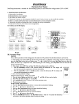
Superior Pro-Heat Programmable Thermostat User’s Manual Model: 031530 The Pro-Heat thermostat is suitable for floor heating systems, controlling the voltage of either a 120VAC or 240VAC. I. Main Functions and Features Blue backlight, clear display Independent keys, easy to operate Can be controlled via sensors or time Factory set with 4 programmed schedules for user’s choice Remote on/off control to connect to a home automation system Calculates the heating time which helps calculate the energy consumption Keyboard lock function II. Product Details & LCD Display 1 III. Installation and Wiring Installation Installation must be carried out by a certified electrician and must comply with national and local electrical codes. o Open the keypad cover and loosen the screw allowing for the separation of the front module from the power module. o Pull outward near the bottom of the front module and lift off. o Find a location for the thermostat in your home. It is for indoor use only. Install the thermostat at a height between 4 and 5 feet above the floor, or on an inside wall. Direct sunshine and heat appliances should be avoided. o Turn off the power to the floor warming system before doing any electrical work. o A dedicated circuit is ideal for the installation of this thermostat. If a dedicated circuit is not possible, make sure there is enough load capacity on an existing circuit to handle the addition of your floor warming system. This circuit should NOT be wired in series with any other device including other GFCIs. o The circuit breaker in the main circuit panel should be 15 amps maximum for a floor warming system totaling 12 amps or less. For a larger system up to 15 amps, use a 20 amps maximum circuit breaker. NEVER exceed 15 amps on the thermostat. o Pull the power supply wiring in to this box, leaving about 6 inches of wire. o Refer to your floor warming system. Pull the floor sensor wire and the power lead wires from your floor warming system up the wall in to this box. o Mount the electrical panel. CAUTION: High Voltage— Disconnect power supply before servicing. Do NOT use where exposed to rain. Mount this control only to a grounded metallic box or a nonmetallic box. Wiring Line1 (L) and Line2 (N) (Line 120VAC/240VAC) and Load1 (LOUT) and Load2 (NOUT) 2 o Connect L and N to the power supply with the wire nuts. Gently tug on the wires to make sure there is no failure in the connection. Consider wrapping the wire nuts with electrical tape to secure the wire connection tightly. o Connect LOUT and NOUT to the floor warming system lead wires with the wire nuts. Gently tug on the wires to make sure there is no failure in the connection. Consider wrapping the wire nuts with electrical tape to secure the wire connection tightly. o Connect the house ground wire to the green lead wire of your floor warming system. o Insert the ends of the floor sensor in to the terminal 1 and 2 and tighten the screws. The blue wire should be secured in terminal 1 and the red wire should be secured in terminal 2. Note: Before continuing, make sure your power supply voltage matches the voltage rating of your floor warming system. Connecting 240VAC to a 120VAC floor warming system will cause overheating and damage to the system and may damage the controller, other wiring, floor coverings, etc. IV. Parameter Setup On/Off Switch Found on the side of the thermostat. The switch must be placed in the “on” position to allow any of the programming to function. When in the “off” position, the system will not heat and the keys will not function. Setting the Date and Time o Press and hold the Day/Time button until the hour begins to flash. Press ▼ or ▲ to adjust the hour. o Press the Day/Time button again and the minutes will begin to flash. Press ▼ or ▲ to adjust the minutes. o Press the Day/Time button again and the day of the week along the top will flash. Press ▼ or ▲ to adjust the day of the week. o Press the Hold/Return button once more and your settings will be stored. Switching Between °F/12 h and °C/24h Format o Press and hold the Options button. °F and 12 h will show on the display. o Press ▼ or ▲ to toggle between °F and 12 h and °C and 24h. o Press the Hold/Return button to store your settings. Setting Your Heating Schedule There are four factory set schedules you can use, designated P1, P2, P3, and P4. 3 You may also manually program your own schedule, designated U1. These can be accessed through the Program button. o Press and hold the Program button. PRO P1, P2, P3, P4 or U1 will be flashing. o Press ▼ or ▲ to toggle between the options. If a pre-set program is desired, select P1-P4 and once highlighted, press the Hold/Return button to accept. These schedules cannot be permanently modified and are as follows: 4 Note: Your pre-set program selection will be indicated in the bottom left corner of the display screen. If a manual program is desired, select U1 and once highlighted, press the Program button once. o The hour will begin flashing for the first of four cycles for your Monday-Friday setting. Use ▼ or ▲ to adjust the hour. Press the Program button once to store. o The minutes will begin flashing for the first of four cycles for your Monday-Friday setting. Use ▼ or ▲ to adjust the minutes. Press the Program button once to store. o The set temperature will begin flashing for the first of four cycles for your Monday-Friday setting. Use ▼ or ▲ to adjust the temperature. Press the Program button once to store. o Now, your hour will begin flashing again for the second of four cycles for your Monday-Friday setting. Repeat these steps for the remaining cycles for Monday-Friday. Following these cycles, you will also be programming 4 cycles each for Saturday and Sunday as well. o When finished, or at any time during the setting of your manual program, you can press the Hold/Return button to store the changes you have made. Note: The U1 program will not show any indication in the bottom left corner of the display screen. Sensor Control and Time Control Mode The thermostat can realize simultaneous detection of the room temperature and floor temperature. There are two sensor options: Flr for floor temperature mode and Air for room temperature mode. The time control mode is indicated by Regu On. o Press and hold the Options button. o Press the Options button once more to show the sensor options. o Use ▼ and ▲ to toggle between Sens Flr, Sens Air and Regu On. o Press Hold/Return to select and store option. Floor Temperature Mode: current temperature displayed is pulled from the installed floor sensor. Heating occurs when current temperature is no more than 10° from the set temperature. Air Temperature Mode: current temperature displayed is pulled from the air sensor in the thermostat. Heating occurs when current temperature is no more than 10° from the set temperature. 5 Floor Limit If the thermostat is set to operate in Air Sense Mode, the display will show the air temperature but the thermostat still monitors the floor sensor if it connected. You may set a floor limit temperature so the system will turn off if the floor sensor temperature exceeds this limit. This will avoid possibly overheating your floor. o Press and hold the Options button. o Use the ▼ or ▲ arrows to highlight the Sens Air option. Press the Options button once to select. o Your Floor Limit should show up next. Use ▼ or ▲ to select a floor limit temperature. o Press the Hold/Return button to store this setting. Calibration This feature allows the ability to slightly adjust the display temperature. Normally this is not recommended and certainly not required, however it may be necessary in special circumstances. o Press and hold the Options button. o Press the Options button until CAL shows on the display with the current temperature and offset value. The offset value is factory set to 0. o Use ▼ or ▲ to adjust the offset value, allowing a range of ±10°F. o Press the Hold/Return button to store this setting. Resetting Factory Defaults You have the option to reset all programming, settings and usage time to the factory defaults. To do this, press and hold the Restore button until Rst Done shows on the display. The thermostat will go through a startup mode and return to the normal operation mode. You will need to reset the day and time following any reset. Note: When resetting to the factory defaults, some malfunction situations may occur. This is caused by information being previously stored incorrectly in the thermostat. Cut the power supply and restart it to solve the problem. V. Operation This thermostat has several ways to control your floor heating system. It is factory set to operate in the program schedule selected but this can be overridden to meet your needs. Heating will show on the display when the system calls for the heating element to turn on. Manual Mode 6 This mode can allow the user to quickly raise the temperature as required. You can temporarily adjust the set temperature as follows. (This set temperature will hold until the next cycle change.) o Press and hold ▼ or ▲ to adjust the set temperature. o Press the Hold/Return button to store this setting. Hold Mode You can hold the current set temperature indefinitely. This can be especially useful when you are on vacation. o Press and hold the Hold/Return button on the main display. Hold will be indicated on the display. o To cancel this hold, press and hold the Hold/Return button again and the indication will disappear from the display. Setback Mode You can use the setback to override the current set temperature. This is especially useful if you have an alternative temperature you repeatedly select when you are away. o Press and hold the Setback button. You will be prompted to enter your setback temperature. o Press Hold/Return and Setback will be indicated on the display and also a set-point temperature. This set-point will hold until the next scheduled program time. o To cancel the setback, press ▼ or ▲. o If a more permanent setback temperature is desired, press and hold the Hold/Return button and Hold will be indicated on the screen as well. To cancel this, you will need to press and hold the Hold/Return button to cancel the hold and then press ▼ or ▲ to cancel the setback. Remote Control Override Mode If your thermostat was installed with Remote Control input from a home automation system, this will override the thermostat when the remote control closes its output switch or relay. Setback and Hold will show on the display and will operate in the setback temperature indefinitely. To cancel this, the Remote Control switch or relay must be opened. Time Control Mode This mode functions like a timer. The heating equipment will start and stop every 15 minutes. You will program a value between 0 and 15 which indicates the length of time in minutes the system will heat out of a possible 15 minutes. Example: A value of 6 will cause it to heat for 6 minutes of the 15 minute cycle and not heat for the remaining 9 7 minutes. 0 would indicate no heating and 15 would indicate continuous heating. o Press and hold the Options button. o Press Options until the Sens options screen displays. o Press ▼ or ▲ to locate Regu On. o Press the Hold/Return button to select. o The screen will now show the heating time (value between 0 and 15) and current cycle time (repeats from 0:00 to 14:59 measured in min:sec). Press and hold ▼ or ▲ to select the heating time. o Press the Hold/Return button to select. Power Consumption Usage This thermostat stores the number of hours it is heating in its memory. This information may be useful in calculating the energy used by the floor heating system. o Press and hold the Options button. o Press Options until Usage and 1d show on the display. o The time shown on the display is the number of hours it was heating today. o Press and hold ▼ and ▲ to toggle between the previous 7-day and 30-day usage. o Press the Hold/Return button to return to normal operation mode. Lockout Feature You have the ability to lock out adjustments by other users. This may be useful in public locations. o Press and hold both ▼ and ▲ at the same time. Lock will indicate on the display and all keys are invalid. o To cancel the lockout, press and hold both ▼ and ▲ at the same time again. The Lock indication should disappear. GFCI Test There is a GFCI (Ground Fault Circuit Interrupter) inside this thermostat. It is designed to help protect from possible electrical shock if the floor warming system has been damaged. To make sure the GFCI is operating properly, test it after the thermostat has been installed and once each month. Note: For this function to work properly, the floor system must be heating. Heating will be indicated on the display. You may need to increase the set temperature temporarily. o Press the GFCI Test button on the side of the thermostat. GFCI Trip should be displayed on the screen and a right light will show next to the GFCI Test. You should also hear a click, indicating power has been removed from the floor warming system. If any of these indicators fail, turn off the thermostat and replace it. Do not continue to use. 8 o To reset the GFCI, slide the On/Standby switch to Standby and then back to On. If the GFCI does not reset, turn the thermostat off. Check the wiring connections, reset by the On/Standby switch, and check resistances on the floor warming system. VI. Specifications Power Supply Maximum Load Maximum Power GFCI Display Range Setting Range Accuracy Storage Temp. AC120/240V, 50/60Hz 15A, resistive 1800W at 120VAC/3600W at 240VAC Class A (5 milliamp trip) 32°F -99°F (0°C -37°C) 41°F -99°F (5°C -37°C) 1°F (0.5°C) 32°F -120°F (0°C –49°C) ETL Listing Control No. 4001076 Programming retained indefinitely. Current time and day will need to be re-set if power is lost for more than 10 minutes. 14AWG wire leads attached to the thermostat. 9