1
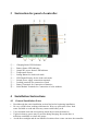
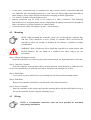
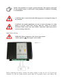
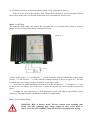
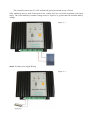
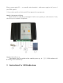
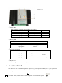
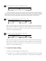
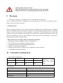
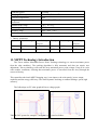
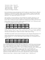
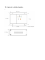
MPPT SOLAR CHARGE CONTROLLER USER - MANUAL Model: SSCM-1224-10A Version:2012-2.0V Patent No.:ZL201120117471.2 Thank you very much for selecting our product! This manual offers important information and suggestions with respect to installation, use and troubleshooting, etc. Please read this manual carefully before using the product and pay attention to the safety recommendations in it. 1 Important Safety Information Save These Instructions This manual contains important safety, installation and operating instructions for controller. The following symbols are used throughout this manual to indicate potentially dangerous conditions or mark important safety instructions, please take care when meeting these symbols. WARNING: Indicates a potentially condition. Use extreme caution when performing this task. CAUTION: Indicates a critical procedure for safe and proper Operation of the controller. NOTE: Indications a procedure or function that is important for the safe and proper operation of the controller. General Safety Information 2 2.1 Read all of the instructions and cautions in the manual before beginning installation. There are no user serviceable parts inside the Tracer. Do not disassemble or attempt to repair the controller. Disconnect the solar module and fuse/breaker near to battery before installing or adjusting the controller. Install external fuses/breakers as required. Do not allow water to enter the controller. Confirm that power connections are tightened to avoid excessive heating from loose connection. General Information Overview The controller is for off-grid solar system and control the charging and discharging of the battery, especially suitable for street light system. The controller features a smart tracking algorithm inside that maximizes the energy from the solar PV module(s) and charge the battery. At the same time, the low voltage disconnect function (LVD) will prevent the battery from over discharging. The controller charging process has been optimized for long battery life and improved system performance. The comprehensive self-diagnostics and electronic protection functions can prevent damage from installation mistakes or system faults. Although the controller is very simple to configure and use, please take your time to read the operator’s manual and become familiar with the controller. This will help you make full use of all the functions and improve your solar PV system. 2.2 Controller Features Our MPPT controller which represents advanced technology. The features are listed below: 12V/24V auto recognition. Advanced maximum power point tracking technology to optimize using the solar system. Peak conversion efficiency of 95%, high Tracking efficiency of 97%. Very fast sweeping of the entire I-V curve several seconds tracking speed. Widely used, automatic recognize day/night. Timer function with 1-17 hours option for street light system. Unique dual timer function, enhance the flexibility of street light system. Sealed, Gel and Flooded battery be suitable. Adopting temperature compensation and correcting the charging and discharging parameters automatically, improving the battery lifetime. Electronic protection: over charging, over discharging ,overload short circuit. Reverse protection: any combination of solar module and battery, without causing damage to any component. Excellent thermal design and nature air cooling. 3 ① ② ③ ④ ⑤ ⑥ ⑦ ⑧ ⑨ ⑩ 4 4.1 Instruction for panel of controller -- Charging Status LED Indicator -- Battery Status LED Indicator -- Output DC power Status LED Indicator -- Temperature Sensor -- Setting Button for load work mode -- LED Digital Display for the load work mode -- Switch power supply connection terminals -- Loading terminals for connection of load -- Battery Terminals for Connection of batteries. -- Solar Module Terminals for Connection of solar modules. Installation Instructions General Installation Notes Read through the entire installation section first before beginning installation. Be very careful when working with batteries. Wear eye protection. Have fresh water available to wash and clean any contact with battery acid. Uses insulated tools and avoid placing metal objects near the batteries. Explosive battery gasses may be present during charging .Be certain there is sufficient ventilation to release the gasses. Avoid direct sunlight and do not install in locations where water can enter the controller. 4.2 Loose power connections and /or corroded wires may result in resistive connections that melt wire insulation, burn surrounding materials, or even cause fire. Ensure tight connections and use cable clamps to secure cables and prevent them from swaying in mobile applications. Use with Gel, Sealed or Flooded batteries only. Battery connection may be wired to one battery or a bank of batteries. The following instructions refer to a singular battery, but it is implied that the battery connection can be made to either one battery or a group of batteries in a battery bank. Select the system cables according to 3A/mm² current density. Mounting NOTE: When mounting the controller, ensure free air through the controller heat sink fins. There should be at least 150mm of clearance above and below the controller to allow for cooling. If mounted in an enclosure, ventilation is highly recommended. WARNING: Risk of explosion! Never install the controller in a sealed enclose with flooded batteries! Do not install in a confined area where battery gas can accumulate. Step 1: Choose Mounting Location Locate the controller on a vertical surface protected from direct sun, high temperature, and water. Step 2: Check for Clearance Place the controller in the location where it will be mounted. Verify that there is sufficient room to run wires and that there is sufficient room above and below the controller for air flow Step 3: Mark Holes Use a pencil or pen to mark the four (4) mounting hole locations on the mounting surface. Step 4: Drill Holes Remove the controller and drill four sizeable holes in the marked locations. Step 5: Secure Controller Place the controller on the surface and align the mounting holes with the drilled holes in step 4. Secure the controller in place using the mounting screws. 4.3 Wiring NOTE: A recommended connection order has been provided for maximum safety during installation. NOTE: The controller is a negative ground controller. Any negative connection of solar module, battery or load can be earth grounded as required. Grounding is recommended. CAUTION: Don’t connect the loads with surge power exceeding the ratings of the controller. CAUTION: For mobile applications, be sure to secure all wiring. Use cable clamps to prevent cables from swaying when the vehicle is in motion. Unsecured cables create loose and resistive connections which may lead to excessive heating and/or fire. Step 1: Battery Wiring WARNING: Risk of explosion or fire! Never short circuit battery positive (+) and negative (-) or cables Figure 4 - 1 Before connecting the battery, measure the battery voltage. It must be over 9V to power the controller. For 24V, the voltage must be greater than 18V to properly detect a 24V battery. The 12/24V battery detection is automatic and the check is only performed at start-up. Wire an in-line fuse holder no more than 150mm from the battery positive terminal. Do not insert a fuse at this time. Confirm the connection correct and then turn on the power. Step 2: Load Wiring The controller load output can connect DC electronic devices of which rated voltage is same as battery’s. Device will provide battery voltage to the loads. Figure 4 - 2 Connect load1 positive (+) and negative (-) to the controller related terminals and connect load2 positive (+) and negative (-) to the controller related terminals as shown in figure 4-2. The load terminals may exist voltage, connect carefully to avoid short circuit. An in-line fuse holder should be wired in series in the load positive (+) or negative (-) wire as shown. Do not insert a fuse at this time. Confirm the connection correct and then turn on the power. If wiring the load connection to a load distribution panel, each load circuit should be fused separately. The total load draw should not exceed the 10A load rating. Step 3: Solar Module Wiring WARNING: Risk of electric shock! Exercise caution when handling solar wiring. The solar module(s) high voltage output can cause severe shock or injury. Cover the solar module(s) from the sun before installing solar wiring. The controller can accept 12V, 24V nominal off-grid solar module arrays. Grid-tie Solar module(s) may be used if the open circuit voltage does not exceed the maximum solar input rating. The solar module(s) nominal voltage must be equal to or greater than the nominal battery voltage. Figure 4 - 3 Step 4: Switch power supply Wiring Figure 4 - 4 Please connect supply DC + - to controller related terminals . And connect supply to AC power of your Utility- power. * If your choice model aren’t this model, Please ignore this step connection. Step 5: Confirmation for Wiring Double-check the wiring in step1 through 4.Confirm correct polarity at each connection. Verify that all six power terminals are tightened. Step 6: Confirm Power-up When battery power is applied and the controller powers up, the ①②③ LEDs indicator will be blinking 3tiems simultaneity. 5 Instructions For LED indications Figure:5-1 ① charge LED: When installation completed and sunlight on solar modules color LED status Controller status System status green Lighting ON MPPT charging normal green blinking MPPT tracking normal Lighting OFF Night normal ② Battery LED: color LED status System status Red Lighting ON Battery low volume Red blinking Battery high volume Lighting OFF normal ③ DC power output LED: Color LED status System status Re-mark Green Lighting ON normal(night) Lighting OFF normal(day) Street-light system Lighting ON normal(24 constant output) Monitor system Green ⑥ Digital Led It’s meaning DC power output time (hours) 6 Load work mode This device be able to do following 8terms output ways, please requested which type are your expectation before you buy. * NOW, YOUR ARE USING TYPE IS √ ITEM. (I)output 1th line, 2nd line all are constant output DC power for monitor system. (II) 1th line,2nd line all are output be:lighting ON/OFF by light dawn-light off dusk- light on When solar module voltage goes below the point of NTTV (Night Time Threshold Voltage) at sunset, the solar controller will recognize the starting voltage and turn on the load after 1 minutes delay; When solar module voltage goes above point of DTTV (Day Time Threshold Voltage), the solar controller will recognize the starting voltage and turn off the load after 1 minutes delay. (III) 1th line is ON/OFF by lighter, 2nd line is lighter and timer control dusk- light on timer- light OFF dawn When solar module voltage goes below the point of NTTV (Night Time Threshold Voltage) at sunset, the solar controller will recognize the starting voltage and turn on the load after 1 minutes delay for several hours which users set on the timer. The timer setting operation is referred to as “Load Work Mode Setting”. (IV) 1th line, 2nd line are all control by light ON + timer control dusk- light on timer- light OFF dawn When solar module voltage goes below the point of NTTV (Night Time Threshold Voltage) at sunset, the solar controller will recognize the starting voltage and turn on the load after 1 minutes delay for several hours which users set on the timer. The timer setting operation is referred to as “Load Work Mode Setting”. 7 Load work mode setting For setting timer value of digitron. Use method as below: setting:press 5secs. The digitron will be blinking,meaning you have already enter in setting condition.。press one time, the value will be plus +1. if right down point is lighting, this value will plus +10. save:stop press key,then 10sec. later, the digitron will stop blinking to be lighting,,this meaning saving successfully. Then the digitron will be turn off about 15sec. later. Digitron will be lighting once connection completed. And turn off after 20sec. if you want to look value of setting, please short press the key. Setting value range: 0-17(hours). ** IF YOU BUY CONSTANT OUTPUT FOR YOUR MONITOR SYSTEM, PLEASE IGNORE ABOVE TIMEER SETTING. AND ALLSO CONTROLLER HAVE ABATE THIS FUNCTION. Remind! When you have completed setting, please to disconnection battery aim to turn off controller, then after 10seconds, re-start connection of battery to turn on controller. This process is intent to make sure the program running in modified setting condition. 8 Protections, Troubleshooting and Maintenance 8.1 Protection PV Array Short Circuit If PV array short circuit occurs, clear it to resume normal operation. PV Overvoltage If PV Overvoltage occurs, the array will remain disconnected until the voltage falls safely below the maximum rating. Load Overload If the load current exceeds the maximum load current rating, the controller will disconnect the load. Overloading must be cleared up through reapply power or pressing the setting button. Load Short Circuit Fully protected against load wiring short-circuit. After one automatic load reconnect attempt, the fault must be cleared by reply power or pressing the setting button. PV Reverse Polarity Fully protection against PV reverse polarity, no damage to the controller will result. Correct the mis-wire to resume normal operation. Battery Reverse Polarity Fully protection against battery reverse polarity, no damage to the controller will result. Correct the mis-wire to resume normal operation. Damaged Local Temperature Sensor If the temperature sensor short-circuited or damaged, the controller will be charging or discharging at the default temperature 25 ℃ to prevent the battery damaged from overcharging or over discharged. High Voltage Transients PV is protected against high voltage transients. In lightning prone areas, additional external suppression is recommended. 8.3 Maintenance The following inspections and maintenance tasks are recommended at least two times per year for best controller performance. Check that the controller is securely mounted in a clean and dry environment. Check that the air flow and ventilation around the controller is not blocked. Clear all dirt or fragments on the heat sink. Check all the naked wires to make sure insulation is not damaged for serious solarization, frictional wear, dryness, insects or rats etc. Maintain or replace the wires if necessary. Tighten all the terminals. Inspect for loose, broken, or burnt wire connections. Check and confirm that LED digital tube is consistent with required. Pay attention to any troubleshooting or error indication. Take necessary corrective action. Confirm that all the system components are ground connected tightly and correctly. Confirm that all the terminals have no corrosion, insulation damaged, high temperature or burnt/discolored sign, tighten terminal screws to the suggested torque. Inspect for dirt, insects and corrosion, and clear up. Check and confirm that lighting arrester is in good condition. Replace a new one in time to avoid damaging of the controller and even other equipments. Warning: Risk of electric shock! Make sure all the power is turned off before above operations, and then follow the corresponding inspections and operations. 9 Warranty The charge controller is warranted to be free from defects for a period of TWO (2) years from the date of shipment to the original end user. We will, at its option, repair or replace any such defective products. Claim procedure: Before requesting warranty service, check the Operation Manual to be certain that there is a problem with the controller. Return the defective product to us with shipping charges prepaid if problem cannot be solved. Provide proof of date and place of purchase. To obtain rapid service under this warranty, the returned products must include the model, serial number and detailed reason for the failure, the module type and size, type of batteries and system loads. This information is critical to a rapid disposition of your warranty claim. This warranty does not apply under the following conditions: 1. Damage by accident, negligence ,abuse or improper use. 2. PV or load current exceeding the rating of product. 3. Unauthorized product modification attempted repair. 4. Damage occurring during shipment. 5. Damage results from acts of nature such as lightning, weather extremes. 6. Irreclaimable mechanical damage. 10 Controller technical data 1. Solar module configuration : system Vmpp Min. Vmpp standard Vmpp Max. 12V 15V 18V 40V 24V 30V 36V 60V 2. Performance Max. voltage from solar panel Max. power from solar panel Controller operation Charge current rated Peak current Good charging efficiency need higher than Vmpp Min 80V 180W (12V) ;360W (24V) 9V Min.(12V system);18V Min(24V system) 10A 15A Controller power Charging efficiency Current of output Max. Temperature compensation coefficient Ambient temp. range Store temp. range Humidity range Enclose 3. Battery parameters System Over-discharge ≦80mA 90%-95%, Peak on 97% 10A -35mV/℃ (25℃ ref.) -35℃ to +55℃ -35℃ to +80℃ 10% - 90% (NC) IP30 12V 10.5V Over-discharge recovery 12.5V 24V 21V 25V floating Over-charge 14V 13.5V Over-charge recovery 14.4V 27.5V 26.5V 28.8V 11. MPPT Technology Introduction The Tracer utilizes Maximum Power Point Tracking technology to extract maximum power from the solar module(s). The tracking algorithm is fully automatic and does not require user adjustment, Tracer technology will track the array maximum power point voltage (Vmp) as it varies with weather conditions, ensuring that maximum power is harvested from the array through the course of the day. This controller takes buck MPPT charging way, it can improve the solar panels’ power output capability and the energy efficiency. The whole dynamic tracking, no manual Settings, speed, high accuracy. The followings are PV solar graph & Power voltage graph Take the 24V system for example. Configure a solar panel as follow: Rated power P=300W Rated power voltage Vmpp=36V Rated powe current Impp=8.33A Open-circuit voltage Voc=44V Short-circuit current Isc=9A P (power) =V (voltage)* I (current) In the rated luminous intensity and temperature, the PV modules can output 300w power. When the charging way is normal, the PV modules voltage is near to the battery’s voltage, the actual output current increase is less. The voltage drop and the controller work in a normal way as the PV solar graph shows. The voltage range of battery is 21V~28.8V. If the controller’s conversion efficiency is 100% and ignore the controller voltage drop, we can know through the curve that when battery voltage is 21V, the actual PV modules output power P=21V* 8.5A =178.5W (power point 3), and know the charging current to battery is 8.5A; but when battery voltage is 28.8V, the actual PV modules output power P=28.8V* 8.4A =242W (power point 1) ,and know the charging current to battery is 8.4A; Power 178.5W 194.4W 211.3W 226.8W 242W Voltage 21V 23V 25V 27V 28.8V Current 8.5A 8.45A 8.45A 8.4A 8.4A From this, it can be seen that PV modules output power increased with the increase of battery voltage, and the average power to battery is 210W (power point 2); in fact the controller’s conversion efficiency won’t be 100%, so the actual average power to battery will less than 210w. The other more than 90W power couldn’t be extracted , caused a waste of energy. This MPPT solar controller works near the maximum power point. Through collecting the date of pv output voltage and current , the maximum power point is determined. That makes PV modules worked at voltage 34V ~38V (this voltage change is dynamic change), the corresponding current is 8.34 A ~7.5 A. Power Voltage Current 283.6W 34V 8.34A 291.6W 300W 35V 36V 8.33A 8.33A 296W 37V 8. 0A 285W 38V 7.5A Also, PV modules output power is 285W~300W, the average power is 292.5W (the unextracted average power 7.5W is dynamic loss). If the controller’s conversion efficiency is 92%, battery can get 268.6W power actually. At this time if battery voltage is 21V, the charging current will be 12.8A; if battery voltage is 28.8V, the charging current is 9.33A . This two currents are both larger than PV output current, so the Energy utilization rate of MPPT way improves more than 27.9% than ordinary way. The above contents are examples for understanding MPPT solar charging, and may have a little difference form practical application. There is a relationship between the ascension of energy’s utilization rate and the difference between solar panels’ Vmpp and battery voltage. The biger the difference between Vmpp and battery voltage is ,the higher energy’s utilization rate is. 12. Controller outside dimension