1
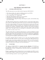
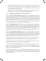
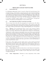
Graph shows squelch setting at 1 turn clockwise.
0
1
2
3
4
5
6
7
8
9
10
Use a relatively low setting for increased reception range.
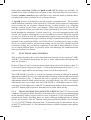
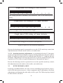
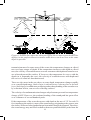
Graph shows squelch setting at 1-1/2 turns clockwise.
0
1
2
3
4
5
6
7
8
9
10
Factory setting. Should work well for most operations.
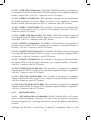
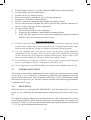
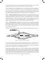
Graph shows squelch setting at 2 turns clockwise.
25
0
1
2
3
4
5
6
7
8
9
10
Not recommended; may disable communications from divers and/or surface.
Figure 5. Effect of squelch sensitivity adjustment
1. If fresh alkaline or fully recharged batteries are not already in the transceiver,
install them, or—if you are using the RB-11 nickel-metal hydride rechargeable
battery pack (sold separately)—recharge the battery through the unit housing.
See Section 4 for battery installation and recharging instructions.
2. Ensure both o-rings (Fig. 2, #4 and #11) are clean and in good condition. They
should both be lightly lubricated with a quality, pure silicone grease. When
reinstalling the transducer after inspecting its o-ring, ensure it is properly seated
and secured.
3. Verify the battery connector wire (Fig. 2, #8) has not been pinched between
the upper and lower housings of the transceiver. (A pinched wire would cause
flooding, damaging the transceiver.)
4. Assure that the upper and lower housings are properly sealed together with no
high spots.
5. Install the earphone microphone (EM) assembly into your full-face mask or
helmet, according to the installation instructions provided with the EM as15