1
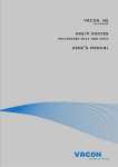
vacon nx ac drives optc3/c5 profibus dp option board user manual INDEX Document code: DPD00892A Date: 17.01.2012 1. GENERAL ........................................................................................................................... 3 2. PROFIBUS DP OPTION BOARD TECHNICAL DATA.............................................................. 4 2.1 2.2 3. General ..................................................................................................................................... 4 Profibus cable........................................................................................................................... 5 PROFIBUS DP ..................................................................................................................... 7 3.1 3.2 4. Introduction .............................................................................................................................. 7 Profiles ..................................................................................................................................... 8 3.2.1 Variable Speed Drive Profile (3.071)................................................................................. 8 PROFIBUS FIELDBUS BOARD LAYOUT AND CONNECTIONS .............................................. 9 4.1 Profibus OPT-C3 option board.................................................................................................. 9 4.1.1 Grounding of bus cable shield in OPT-C3 ...................................................................... 10 4.2 Profibus OPT-C5 option board................................................................................................ 15 4.2.1 Grounding of a D-connector: .......................................................................................... 15 4.3 Bus terminal resistors ........................................................................................................... 16 4.4 LED indications ....................................................................................................................... 17 5. INSTALLATION OF VACON NX PROFIBUS BOARD ............................................................ 19 6. COMMISSIONING .............................................................................................................. 21 6.1 6.2 7. Fieldbus board parameters .................................................................................................... 21 Start-up test ........................................................................................................................... 23 PROFIBUS-VACON NX INTERFACE .................................................................................. 24 7.1 7.2 7.3 7.4 General ................................................................................................................................... 24 Operation mode ...................................................................................................................... 24 PPO types ............................................................................................................................... 25 Process data ........................................................................................................................... 26 7.4.1 Control word ................................................................................................................... 27 7.4.2 Status word..................................................................................................................... 28 7.4.3 State machine ................................................................................................................. 29 7.4.4 Reference 1 .................................................................................................................... 30 7.4.5 Actual value 1 ................................................................................................................. 30 7.4.6 PD1…PD8 ........................................................................................................................ 30 7.5 Parameter data ...................................................................................................................... 32 7.5.1 Parameter field .............................................................................................................. 33 7.6 Example messages ................................................................................................................ 35 8. FAULT TRACKING ............................................................................................................. 37 9. Type files .......................................................................................................................... 38 9.1 10. GSD-file (“Profibus Support Disk” files: vac29500.GSD, vac29500.GSE) ............................... 38 APPENDIX ........................................................................................................................ 39 Tel.+358 (0)201 2121 • Fax +358 (0)201 212 205 general 1. vacon • 3 GENERAL Vacon NX frequency converters can be connected to the Profibus DP using a fieldbus board. The converter can then be controlled, monitored and programmed from the Host system. The Profibus fieldbus board shall be installed in slot E on the control board of the frequency converter. Internal components and circuit boards are at high potential when the frequency converter is connected to the power source. This voltage is extremely dangerous and may cause death or severe injury if you come into contact with it. WARNING! NOTE! You can download the English and French product manuals with applicable safety, warning and caution information from www.vacon.com/downloads. REMARQUE Vous pouvez télécharger les versions anglaise et française des manuels produit contenant l’ensemble des informations de sécurité, avertissements et mises en garde applicables sur le site www.vacon.com/downloads. 24-hour support +358 (0)40 8371 150 • Email: [email protected] 1 4 • vacon technical data 2. PROFIBUS DP OPTION BOARD TECHNICAL DATA 2.1 General Profibus DP connections Communications Environment Interface Data transfer method Transfer cable Electrical isolation Profibus DP PPO types Baud rate Addresses Ambient operating temperature Storing temperature Humidity Altitude Vibration Safety Table 2-1. Profibus technical data OPTC3: Pluggable connector (5.08mm) OPTC5: 9-pin DSUB connector (female) RS-485, half-duplex Twisted pair (1 pair and shield) 500 VDC As described in document “Profibus Profile for variable speed drives, Profidrive” 1, 2, 3, 4, 5 9.6 kbaud to 12 Mbaud 2 to 126 –10°C…55°C –40°C…60°C <95%, no condensation allowed Max. 1000 m 0.5 G at 9…200 Hz Fulfils EN50178 standard Tel.+358 (0)201 2121 • Fax +358 (0)201 212 205 2 technical data 2.2 vacon • 5 Profibus cable Profibus devices are connected in a bus structure. Up to 32 stations (master or slaves) can be connected in one segment. The bus is terminated by an active bus terminator at the beginning and end of each segment (see Figure 2-1). To ensure error-free operation, both bus terminations must always be powered. When more than 32 stations are used, repeaters (line amplifiers) must be used to connect the individual bus segments. The maximum cable length depends on the transmission speed and cable type (see Table 2-3). The specified cable length can be increased using the repeaters. The use of more than 3 repeaters in series is not recommended. Parameter Impedance Line A 135 ... 165 Ω (3 to 20 Mhz) Capacity < 30 pF/m Resistance < 110 Ω / km Wire gauge > 0,64 mm Conductor area > 0,34 mm2 Table 2-2. Line parameters Line B 100 ... 130 Ω ( f > 100kHz) < 60 pF/m > 0,53 mm > 0,22 mm2 Baud rate 9.6 19.2 93.75 187.5 (kbit/s) Length line A (m) 1200 1200 1200 1000 1200 1200 1200 600 Length line B (m) Table 2-3. Line length for different transmission speeds E.g. following cables can be used: Belden Profibus Data Cable Olflex Profibus Cable Siemens SINEC L2 LAN cable for Profibus 500 1500 400 200 200 - 300012000 100 - 3079A 21702xx 6XV1 830-0AH10 NOTE! 1. Minimum distance between power and bus cables is 30cm. 2. Minimum cable length between two stations of 1m is recommended. 24-hour support +358 (0)40 8371 150 • Email: [email protected] 2 6 • vacon technical data Figure 2-1. Cabling and bus termination Tel.+358 (0)201 2121 • Fax +358 (0)201 212 205 2 profibus dp 3. PROFIBUS DP 3.1 Introduction vacon • 7 Profibus is a vendor-independent, open fieldbus standard for a wide range of applications in manufacturing, process and building automation. Vendor independence and openness are guaranteed by the Profibus standard EN 50 170. With Profibus, devices of different manufacturers can communicate without special interface adjustments. Profibus can be used for both high-speed time critical data transmission and extensive complex communication tasks. The Profibus family consists of three compatible versions. Profibus DP Optimized for high speed and inexpensive hookup, this Profibus version is designed especially for communication between automation control systems and distributed I/O at the device level. ProfibusDP can be used to replace parallel signal transmission with 24 V or 0 to 20 mA. Profibus PA Profibus PA is designed especially for process automation. It permits sensors and actuators to be connected on one common bus line even in intrinsically-safe areas. Profibus PA permits data communication and power over the bus using a 2-wire technology according to the international standard IEC 1158-2. Profibus FMS Profibus FMS is the general-purpose solution for communication tasks at the cell level. Powerful FMS services open up a wide range of applications and provide great flexibility. Profibus FMS can also be used for extensive and complex communication tasks. Profibus specifies the technical and functional characteristics of a serial fieldbus system with which decentralized digital controllers can be networked together from the field level to the cell level. Profibus distinguishes between master devices and slave devices. Master devices determine the data communication on the bus. A master can send messages without an external request when it holds the bus access rights (the token). Masters are also called 'active stations' in the Profibus protocol. Slave devices are peripheral devices. Typical slave devices include input/output devices, valves, drives and measuring transmitters. They do not have bus access rights and they can only acknowledge received messages or send messages to the master when requested to do so. Slaves are also called 'passive stations'. 24-hour support +358 (0)40 8371 150 • Email: [email protected] 3 8 • vacon 3.2 profibus dp Profiles The Profibus DP protocol defines how user data are to be transmitted between the stations over the bus. User data are not evaluated by the Profibus DP transmission protocol. The meaning is specified in the profiles. In addition, the profiles specify how Profibus DP is to be used in the application area. The following Profibus DP profile is used in VACON NX Profibus Fieldbus board. 3.2.1 Variable Speed Drive Profile (3.071) Leading manufacturers of drive technology have jointly defined the PROFIDRIVE profile. The profile specifies how the drives are to be parameterized and how the setpoints and actual values are to be transmitted. This enables drives from different vendors to be exchanged. The profile contains necessary specifications for speed control and positioning. It specifies the basic drive functions while leaving sufficient freedom for application-specific expansions and further developments. The profile describes the mapping of the application functions for DP or FMS. Tel.+358 (0)201 2121 • Fax +358 (0)201 212 205 3 fieldbus board layout and connections 4. vacon • 9 PROFIBUS FIELDBUS BOARD LAYOUT AND CONNECTIONS Vacon Profibus Fieldbus Board is connected to the fieldbus through either a 5-pin pluggable bus connector (board OPT-C3) or a 9-pin female sub-D-connector (board OPT-C5). The communication with the control board takes place through the standard Vacon Interface Board Connector. 4.1 Profibus OPT-C3 option board 1 2 3 4 5 X6 X1 Bus connector Jumpers Interface board connector Figure 4-1. Vacon Profibus option board OPT-C3 Signal Shield VP RxD/TxD –P RxD/TxD –N DGND Connector 1 2 3 4 5 Description Cable shield Supply voltage – plus (5V) Receive/Transmit data – plus (B) Receive/Transmit data – minus (A) Data ground (reference potential for VP) Table 4-1. OPT-C3 bus connector signals 24-hour support +358 (0)40 8371 150 • Email: [email protected] 4 10 • vacon 4.1.1 fieldbus board layout and connections Grounding of bus cable shield in OPT-C3 The bus cable shield can be grounded in three different ways: a) directly to the frequency converter frame b) to the frame of the frequency converter through an RC filter c) clamping the cable to the converter frame (recommended) Note: Normally, the option board has already been installed in slot E of the control board. It is not necessary to detach the whole board for the grounding of the bus cable shield. Just detach the terminal block. 4.1.1.1 1 Grounding the bus cable shield directly to the frequency converter frame using jumper X1 Set jumper X1 in ON position: ON OFF X1 Figure 4-2. Jumper X1 positions 2 Strip about 5 cm of the Profibus cable as shown in the picture. Note: Do the same for both bus cables (except for the last device). However, since the grounding shall be done on one cable only cut off the exposed part of the other grounding cable. Figure 4-3. Tel.+358 (0)201 2121 • Fax +358 (0)201 212 205 4 fieldbus board layout and connections 3 vacon • 11 Leave no more than 1 cm of the red and green data cable outside the terminal block and strip the data cables at about 0.5 cm to fit in the terminals. See pictures below. Note: Do this for both bus cabels. Figure 4-4. Figure 4-5. 24-hour support +358 (0)40 8371 150 • Email: [email protected] 4 12 • vacon 4 fieldbus board layout and connections We recommend you to use an Abico connector to fit the grounding cable into the grounding terminal (#1). Insert the red and green data cables of both Profibus cables into terminals #3 (red) and #4 (green). RG Figure 4-6. 5 Place the Profibus board into slot E of the control board (see board installation on page 19) and fix both the Profibus cables on the frame with the clamp. Figure 4-7. Tel.+358 (0)201 2121 • Fax +358 (0)201 212 205 4 fieldbus board layout and connections 4.1.1.2 vacon • 13 Grounding the bus cable shield directly to the frequency converter frame using an RC-filter We recommend you to do the grounding in this manner when the distance between the devices exceeds 50 meters (55 yds.). When the distance between the devices is long disturbances (e.g. voltage spikes) are more likely to appear. In this grounding method, the disturbances are filtered out. Even if the ground planes of A, B and C are different (which is very typical e.g. in construction) there is no current between them because the points do not have a ground connection. NOTE: If a potential difference occurs between the grounding points, an equalization current can flow through a shield connected at both ends. In this case, install an additional potential equalization line and set this jumper X1 in ON position. A B Profibus cable C Profibus cable Profibus cable Figure 4-8. Grounding with RC filter 1 Set jumper X1 in OFF position ON OFF X1 Figure 4-9. Jumper X1 positions 2 Carry out the grounding in the same way as advised in Chapter 4.1.1.1. 24-hour support +358 (0)40 8371 150 • Email: [email protected] 4 14 • vacon 4.1.1.3 fieldbus board layout and connections Grounding by clamping the cable to the converter frame This manner of grounding is the most effective and especially recommended when the distances between the devices are relatively short (see 4.1.1.2). In this manner of grounding, the position of jumper X1 is of no importance. Profibus cable Profibus cable Profibus cable Figure 4-10. Grounding by clamping the cable to the converter frame 1. Strip about 5 cm of the Profibus cable in the same way as shown in Figure 4-3 but cut off the grey cable shield. Remember to do this for both bus cables (except for the last device). 2. Leave no more than 1 cm of the red and green data cable outside the terminal block and strip the data cables at about 0.5 cm to fit in the terminals. See Figure 4-4 and Figure 4-5. Note: Do this for both bus cabels. 3. Insert the red and green data cables of both Profibus cables into terminals #3 (red) and #4 (green). See Figure 4-6. 4. Strip the Profibus cable at such a distance from the terminal that you can fix it to the frame with the grounding clamp. See Figure 4-11. 5. Ground the cable shield at both ends and on all loads by 360° connection. Figure 4-11a. Figure 4-11b. Tel.+358 (0)201 2121 • Fax +358 (0)201 212 205 4 fieldbus board layout and connections 4.2 vacon • 15 Profibus OPT-C5 option board 5 4 9 3 8 2 7 1 6 X6 X1 Bus connector Jumpers Interface board connector Figure 4-12. Vacon Profibus option board OPT-C5 Signal Connector Description Shield 1 Cable shield RxD/TxD-P 3 Receive/Transmit data - plus (B), RED DGND 5 Data Ground (reference potential for VP) VP 6 Supply voltage – plus (5V) RxD/TxD-N 8 Receive/ Transmit data - minus (A), GREEN Table 4-2. OPT-C5 bus connector signals E.g. following connectors can be used (180° cable outlet): Phoenix Siemens 4.2.1 SUBCON-PLUS-PROFIB/AX/SC Profibus connector 27 44 38 0 6GK1 500-0EA02 Grounding of a D-connector: Figure 4-13. Remove the screw of the grounding clamp 24-hour support +358 (0)40 8371 150 • Email: [email protected] 4 16 • vacon fieldbus board layout and connections 15 mm Figure 4-14. Strip the cable according to the picture Max. length of the Dconnector 60 mm Push the clamp while tightening the screw Figure 4-15. Attach the D-connector and tighten the grounding plate Tel.+358 (0)201 2121 • Fax +358 (0)201 212 205 4 fieldbus board layout and connections 4.3 vacon • 17 Bus terminal resistors If Vacon is the last device of the Profibus line the bus termination must be set. Use jumper X6 (ON position) or external termination resistors (e.g. in DSUB-9 connector). See Figure 4-16. NOTE! Termination works properly when the drive has power (active termination) connected. ON OFF X6 Figure 4-16. Using jumper X6 to set the bus termination. 4.4 LED indications The three LED indications next to the connector show the present statuses of the Profibus (red), the Profibus board (yellow) and the Fieldbus Module (green). From the user's viewpoint, the first two are the most significant. Red Yellow Green 1 2 3 4 5 X6 X1 Figure 4-17. LED indications on the Profibus board 24-hour support +358 (0)40 8371 150 • Email: [email protected] 4 18 • vacon fieldbus board layout and connections Profibus status LED (PS) LED is: OFF ON RED Meaning: Profibus communicates normally. • Data exchange between Master and Slave Profibus communication is broken or not started. • Bus cable broken or incorrectly connected • Wrong configuration or parametrization data of Master • Master is off line or shut down Profibus board status LED (BS) YELLOW LED is: OFF ON Blinking fast (once/sec) Blinking slow (once/5 secs) Meaning: Option board not activated Option board in initialisation state waiting for activation command from the frequency converter Option board is activated and in RUN state • Option board is ready for external communication Option board is activated and in FAULT state • Internal fault of option board Fieldbus status LED (FS) LED is: OFF ON Blinking fast (once/sec) Blinking slow (once/5 secs) GREEN Meaning: Fieldbus module is waiting for parameters from the frequency converter • No external communication Fieldbus module is activated • Parameters received and module activated • Module is waiting for messages from the bus Module is activated and receiving messages from the bus Module is in FAULT state • No messages from Master within the watchdog time • Bus broken, cable loose or Master off line Tel.+358 (0)201 2121 • Fax +358 (0)201 212 205 4 installation of vacon nx profibus board 5. vacon • 19 INSTALLATION OF VACON NX PROFIBUS BOARD It is not allowed to add or replace option boards or fieldbus boards on a frequency converter with the power switched on! This may damage the boards. ! NOTE A Vacon NX frequency converter B Remove the cable cover. C Open the cover of the control unit. D Install Profibus DP option board in slot E on the control board of the frequency converter. Make sure that the grounding plate (see below) fits tightly in the clamp. 1 2 3 4 5 X6 X1 24-hour support +358 (0)40 8371 150 • Email: [email protected] 5 20 • vacon installation of vacon nx profibus board E Make a sufficiently wide opening for your cable by cutting the grid as wide as necessary. F Close the cover of the control unit and the cable cover. Tel.+358 (0)201 2121 • Fax +358 (0)201 212 205 5 commissioning 6. vacon • 21 COMMISSIONING READ FIRST CHAPTER 8 'COMMISSIONING' IN VACON NX USER'S MANUAL (Document nr. ud00701, please visit http://www.vacon.com/support/documents.html). 6.1 Fieldbus board parameters The Vacon Profibus board is commissioned with the control keypad by giving values to appropriate parameters in menu M7 (for locating the expander board menu see Vacon NX User's Manual, Chapter 7). Expander board menu (M7) The Expander board menu makes it possible for the user 1) to see what expander boards are connected to the control board and 2) to reach and edit the parameters associated with the expander board. Enter the following menu level (G#) with the Menu button right. At this level, you can browse through slots A to E with the Browser buttons to see what expander boards are connected. On the lowermost line of the display you also see the number of parameter groups associated with the board. If you still press the Menu button right once you will reach the parameter group level where there are two groups: Editable parameters and Monitored values. A further press on the Menu button right takes you to either of these groups. Profibus parameters To commission the Profibus board, enter the level G7.5.1.# from the Parameters group (G7.5.1). Give desired values to all Profibus parameters (see Figure 6-1 and Table 6-1). I/Oterm I/Oterm Expander Board G1 G5 NXOPTC5 Slave address Parameters P1P4 G1 G2 READY I/Oterm 126 READY READY READY I/Oterm READY I/Oterm CHANGE VALUE Slave address 126 enter CONFIRM CHANGE Figure 6-1. Changing the Profibus board commissioning parameter values 24-hour support +358 (0)40 8371 150 • Email: [email protected] 6 22 • vacon commissioning # 1 2 Name SLAVE ADDRESS BAUD RATE 3 PPO TYPE 4 OPERATE MODE Default 126 10 (=AUTO) Range 2…126 1 - 9.6 kBaud 2 - 19.2 kBaud 3 - 93.75 kBaud 4 - 187.5 kBaud 5 - 500 kBaud 6 - 1.5 Mbaud 7 - 3 MBaud 8 - 6 Mbaud 9 - 12 Mbaud 10 – AUTOMATIC 1 - PPO1 2 - PPO2 3 - PPO3 4 - PPO4 5 - PPO5 1 – PROFIDRIVE 2 – BYPASS 3 – ECHO Description Communication speed in baud Parameter, CW/SW, Ref/Act Parameter, CW/SW, Ref/Act, PD1-PD4 CW/SW, Ref/Act CW/SW, Ref/Act, PD1-PD4 Parameter, CW/SW, Ref/Act, PD1-PD8 Use mode ”PROFIDRIVE” with standard applications Table 6-1. Profibus parameters The parameters of every device must be set before connecting to the bus. Especially the parameters “SLAVE ADDRESS” and “PPO TYPE” must be the same as in the master configuration. Profibus status To see the present status of the Profibus fieldbus, enter the Profibus status page from Monitor menu (G7.5.2). See Figure 6-2 and Table 6-2 below. READY I/Oterm Monitor V1 V1 READY I/Oterm Profibus status 2516.0 Profibus status Message counter Figure 6-2. Profibus status Profibus status 0 Waiting parameter from Master 1 Waiting configuration from Master 2 Communication established Table 6-2. Profibus status indications Tel.+358 (0)201 2121 • Fax +358 (0)201 212 205 6 commissioning 6.2 vacon • 23 Start-up test Frequency converter application Choose Fieldbus (Bus/Comm) as the active control place (see Vacon NX User's Manual, Chapter 7.3.3). Master software 1. Set Control Word value to 0hex. 2. Set Control Word value to 47Fhex. 3. Frequency converter status is RUN 4. Set Reference value to 5000 (=50,00%). 5. The Actual value is 5000 and the frequency converter output frequency is 25,00 Hz 6. Set Control Word value to 477hex. 7. Frequency converter status is STOP If Status Word bit 3 = 1 Status of frequency converter is FAULT. 24-hour support +358 (0)40 8371 150 • Email: [email protected] 6 24 • vacon 7. profibus-vacon nx interface PROFIBUS-VACON NX INTERFACE Features of the Profibus-Vacon NX interface: • Direct control of Vacon NX ( e.g. Run, Stop, Direction, Speed reference, Fault reset) • Full access to all Vacon NX parameters • Monitor Vacon NX status (e.g. Output frequency, Output current, Fault code) 7.1 General Data transfer between Profibus DP master and slave takes place via the input/output data field. The Master writes to Slave’s output data and the Slave answers by sending the contents of its input data to the Master. The contents of the input/output data is defined in the device profile. The device profile for frequency converters is PROFIDRIVE. The Vacon NX frequency converter can be controlled by Profibus DP Master using the PPO-types defined in Profidrive (see Chapter 7.3). When fieldbus has been selected as the frequency converter’s active control place, the frequency converter’s operation can be controlled from the Profibus DP Master. Whether or not the active control place is fieldbus, the frequency converter can be monitored and its parameters set by the Profibus DP Master. Profibus Master Protocol Trailer OUTPUT Data Protocol Header Protocol Header INPUT Data Protocol Trailer Profibus Slave Figure 7-1. Data transfer between Profibus Master and Slaves 7.2 Operation mode The parameter Operation mode (G7.5.1.4, see above) defines how the input/output data is handled on the option board. PROFIDRIVE • Data transfer follows the document Profibus Profile for variable speed drives, PROFIDRIVE. BYPASS • The information of the Process Data field is transferred to the application interface without handling • Parameter setting takes place according to the Profidrive definition ECHO • The OUTPUT data written by the Master is echoed back to the Master in the INPUT field • The data is not shown in the frequency converter but the echoing is carried out on the option board • This mode can be used when the function of the bus connection is tested Tel.+358 (0)201 2121 • Fax +358 (0)201 212 205 7 profibus-vacon nx interface 7.3 vacon • 25 PPO types PPOs (Parameter/Process Data Object) are the communication objects in PROFIBUS DP. The PPOs in Vacon NX: Parameter Field ID IND Process Data Field VALUE CW REF PD1 PD2 PD3 PD4 PD5 PD6 PD7 PD8 SW ACT PD1 PD2 PD3 PD4 PD5 PD6 PD7 PD8 PPO 1 PPO 2 PPO 3 PPO 4 PPO 5 Descriptions: Byte ID Parameter type and number IND Parameter subindex VALUE Parameter value CW Control Word SW Status Word REF Reference Value 1 ACT Actual Value 1 PD Process Data 24-hour support +358 (0)40 8371 150 • Email: [email protected] 7 26 • vacon 7.4 profibus-vacon nx interface Process data The process data field is used to control the device (e.g. Run, Stop , Reference, Fault Reset) and in reading quick actual values (e.g. Output frequency, Output current, Fault code). The size of the field varies between 2…20 bytes. The field is structured as follows: Process Data Master -> Slave (max 20 bytes) CW REF PD1 PD2 PD3 PD4 PD5 PD6 PD7 PD8 PD4 PD5 PD6 PD7 PD8 Process Data Slave -> Master (max 20 bytes) SW ACT PD1 PD2 PD3 The use of process data depends on the application. In a typical situation the device is started and stopped via the ControlWord (CW) written by the Master and the Rotating speed is set with Reference (REF). Via PD1…PD8 the device can be given other reference values (e.g. Torque reference). With the help of the StatusWord (SW) read by the Master, the status of the device can be seen. Actual Value (ACT) and PD1…PD8 show the other actual values. See Figure 7-2. Profibus Board Frequency Converter ControlWord ProcessData 1 … APPLICATION PROFIBUS MASTER Reference 1 ProcessData 8 StatusWord Actual Value 1 ProcessData 1 … ProcessData 8 Figure 7-2. Control of the frequency converter through Profibus Tel.+358 (0)201 2121 • Fax +358 (0)201 212 205 7 profibus-vacon nx interface 7.4.1 vacon • 27 Control word CW REF PD1 PD2 PD3 PD4 PD5 PD6 PD7 PD8 The Control command for the state machine (see Figure 7-3.) The state machine describes the device status and the possible control sequence of the frequency converter. The control word is composed of 16 bits that have the following meanings: Bit Description Value = 0 0 STOP 1 (by ramp) 1 STOP 2 (by coast) 2 STOP 3 (by ramp) 3 RUN DISABLE 4 No Action 5 No Action 6 No Action 7 No Action 8 No Action 9 No Action 10 Disable Profibus control 11 Fieldbus DIN1=OFF 12 Fieldbus DIN2=OFF 13 Fieldbus DIN3=OFF 14 Fieldbus DIN4=OFF 15 Fieldbus DIN5=OFF Table 7-1. Control word bit descriptions Value = 1 ON 1 ON 2 ON 3 ENABLE START START START FAULT RESET (0 -> 1) No Action No Action Enable Profibus control Fieldbus DIN1=ON Fieldbus DIN2=ON Fieldbus DIN3=ON Fieldbus DIN4=ON Fieldbus DIN5=ON With the help of the control word, start and stop commands can be given to the device. Also a fault can be acknowledged. Command ControlWord RUN 047Fhex STOP 1 047Ehex STOP 2 047Dhex STOP 3 047Bhex RUN DISABLE 0477hex FAULT RESET (step 1) bit 7 = 0 FAULT RESET (step 2) bit 7 = 1 Table 7-2. Commands with control word Description Start motor if ”Fieldbus” is active control source Stop by Ramp Stop by Coast Stop by Ramp Stop by Coast Rising edge to bit 7 As shown above, there are several stop modes. It depends on the operating situation, which mode is selected. Note! In Vacon NX frequency converter STOP1 and STOP3 are identical. Also STOP2 and RUN DISABLE are identical. Commands STOP1 and STOP3 can be used only with either one of the motor control modes (P2.6.1) Frequency control or Speed control selected and the fieldbus selected as the control place. 24-hour support +358 (0)40 8371 150 • Email: [email protected] 7 28 • vacon 7.4.2 profibus-vacon nx interface Status word SW ACT PD1 PD2 PD3 PD4 PD5 PD6 PD7 PD8 Information about the status of the device and messages is indicated in the Status word. The Status word is composed of 16 bits that have the following meanings: Bit Description Value = 0 0 Not Ready (initial) 1 Not Ready 2 DISABLE 3 NO FAULT 4 STOP 2 5 STOP 3 6 START ENABLE 7 No Warning 8 Reference ≠ Actual value 9 Fieldbus control OFF 10 Not used 11 Not used 12 FC stopped 13 FC not ready 14 Not used 15 Not used Table 7-3. Status word bit descriptions Value = 1 READY 1 ** READY 2 ** ENABLE ** FAULT ACTIVE * NO STOP 2 ** NO STOP 3 ** START DISABLE ** Warning * Reference = Actual value * Fieldbus control ON * Not used Not used Running * FC ready * Not used Not used * Comes straight from the frequency converter ** Bits of the State Machine Tel.+358 (0)201 2121 • Fax +358 (0)201 212 205 7 profibus-vacon nx interface 7.4.3 vacon • 29 State machine The state machine describes the device status and the possible control sequence of the frequency converter. The state transitions can be generated by using the “Control word”. The “Status word” indicates the current status of the state machine. The modes INIT, STOP, RUN and FAULT (see Figure 7-3. ) correspond to the actual mode of the Frequency converter. Underlined and SW = “Status word”. Not Underlined and CW = “Control word”. Power ON Fault STOP 1; CW Bit0=0 STATE: INIT DISABLE; SW Bit6=1 STOP by ramp READY 2; SW Bit1=0 Set CW Bit0=0, Bit10=1 xxxx x1xx xxxx xxx0 STATE: STOP READY 1; SW Bit0=0 DISABLE; SW Bit6=0 Set CW Bit1=1, Bit2=1 xxxx x1xx xxxx x110 RUN DISABLE; CW Bit3=0 FAULT FAULT ACTIVE; SW Bit3=1 STATE: STOP Reset fault CW Bit7=0 CW Bit7=1 STOP 2; CW Bit1=0 STOP by P2.4.7 STOP 2; SW Bit4=0 READY 1; SW Bit0=1 STOP by P2.4.7 RUN DISABLE; SW Bit2=0 Set CW Bit0=1 xxxx x1xx xxxx x111 STOP 3; CW Bit2=0 STATE: STOP READY 2; SW Bit1=1 STOP by ramp Set CW Bit3=1 xxxx x1xx xxxx 1111 STOP 3; SW Bit5=0 STATE: STOP ENABLE; SW Bit2=1 Set CW Bit4=1, Bit5=1, Bit6=1 xxxx x1xx x111 1111 (hex047F) STATE: RUN RUNNING Figure 7-3. 24-hour support +358 (0)40 8371 150 • Email: [email protected] 7 30 • vacon 7.4.4 profibus-vacon nx interface Reference 1 CW REF PD1 PD2 PD3 PD4 PD5 PD6 PD7 PD8 This is the reference 1 to the frequency converter. Used normally as Speed reference. The allowed scaling is –10000...10000. In the application, the value is scaled in percentage of the frequency area between set minimum and maximum frequency. -10000 = 0 = 10000 = 7.4.5 100,00 % (Direction reverse) 0,00 % (Direction forward) 100,00 % (Direction forward) Actual value 1 SW ACT PD1 PD2 PD3 PD4 PD5 PD6 PD7 PD8 This is the actual value from the frequency converter. Used normally as Speed reference, with the value between –10000...10000. In the application, the value is scaled in percentage of frequency area between set minimum and maximum frequency. -10000 = 0 = 10000 = 7.4.6 100,00 % (Direction reverse) 0,00 % (Direction forward) 100,00 % (Direction forward) PD1…PD8 ProcessData Master -> Slave CW REF PD1 PD2 PD3 PD4 PD5 PD6 PD7 PD8 The Master can write max. 8 additional setting values to the device with the help of the Process Data. How these setting values are used is totally dependent on the application in use. ProcessData Slave -> Master SW ACT PD1 PD2 PD3 PD4 PD5 PD6 PD7 PD8 The master can read the frequency converter’s actual values using the process data variables. Depending on the used application, the contents are either standard or can be selected with a parameter. Tel.+358 (0)201 2121 • Fax +358 (0)201 212 205 7 profibus-vacon nx interface vacon • 31 Pr o f ib u s DP m a ster PD1 PD2 PD3 PD4 PD5 PD6 PD7 PD8 VA CO N N X 1 Output Frequency 2 Motor Speed . . . Selector Parameter or fixed variable N XB1 Figure 7-4. Control of Process data (see APPENDIX) 24-hour support +358 (0)40 8371 150 • Email: [email protected] 7 32 • vacon 7.5 profibus-vacon nx interface Parameter data The Vacon variables and fault codes as well as the parameters can be read and written using PPO types 1, 2 and 5. The reading and writing can be done via the parameter field of the profibus message frame. The device parameters can be read and written and the actual values read with the help of the parameter field. The size of the parameter field is 8 bytes and it is divided into three parts, ID, Index and Value. ID VALUE IND Profibus Board Frequency Converter ID VALUE APPLICATION PROFIBUS MASTER Read/Write from Drive IND ID Answer from Drive IND VALUE Figure 7-5. Transfer of parameter data The parameter addresses are determined in the application. Every parameter and actual value has been given an ID number in the application. The ID numbering of the parameter as well as the parameter ranges and steps can be found in the application manual in question. The parameter value shall be given without decimals. The ID numbers of each parameter/actual value are found in the application manual. The ID numbers are grouped as follows: Parameter ID 0 1 … 99 37 100 101… 899 900 … 999 1000 1001…1999 Group Not used Actual Values Active Fault Code Not Used Parameter Reserved Not Used Parameter Description Reserved for Profibus internal usage Table 7-4. Grouping of ID numbers Tel.+358 (0)201 2121 • Fax +358 (0)201 212 205 7 profibus-vacon nx interface 7.5.1 vacon • 33 Parameter field Task and parameter ID ID IND VALUE ID byte1 15 14 ID byte2 13 12 11 10 9 8 7 6 5 4 3 2 1 0 SM Parameter Number (= Vacon ID number) Request/Response type SM: Spontaneous bit (not used) Request/Response types Request Function Response Function 0 No request 0 No response 1 Read parameter value (word) 1 Parameter value ready (word) 2 Write parameter value (word) 7 Request rejected (+fault code) Fault Numbers (if response = 7) Fault Number 0 1 2 17 18 101 Description Illegal Parameter Parameter is read only ( e.g. actual values) Parameter value is out of limits Request temporarily rejected (e.g. can be changed only for STOP state) Other fault Unknown request type 24-hour support +358 (0)40 8371 150 • Email: [email protected] 7 34 • vacon profibus-vacon nx interface Index ID IND VALUE Not in use Data Value ID IND VALUE Data word 1 (HIGH) byte 0 Data word 2 (LOW) byte 1 byte 2 byte3 In writing mode the data to be written is placed in the field “Data word 2”. In reading mode the answer is in the field ”Data word 2”. “Data word 1” is normally zero. Tel.+358 (0)201 2121 • Fax +358 (0)201 212 205 7 profibus-vacon nx interface 7.6 vacon • 35 Example messages Example1 , (PPO1 mode): Read parameter number 102 (ID=102). Start frequency converter and set speed reference 50,00%. Command Master - Slave: ID 1066 hex IND VALUE CW 0000 hex 0000 0000 hex 047F hex REF 1388 hex 1 - Read parameter value 066 - Parameter 102 (= e.g. maximum frequency ) 0000 - No meaning 0000 0000 - No meaning 04 7F- Start command (see chapter control word and state machine) Speed ref. 50,00% (= 25,00 Hz if parameter min. frequency 0 Hz and max. frequency 50 Hz) PPO1 frame (Parameter Field as Bold text): 10 66 00 00 00 00 00 00 04 7F 13 88 Answer Slave - Master: ID 1066 hex IND VALUE SW 0000 hex 0000 1388 hex 0000 hex ACT 0000 hex 1 - Parameter value ready 066 - Parameter 102 (= Maximum frequency ) 0000 - No meaning 0000 1388 - Parameter value = 1388hex ( 50,00 Hz) 0000 - frequency converter status (see chapter status word and state machine) Current speed 0,00% (= 0,00 Hz if parameter min. frequency 0 Hz and max. frequency 50 Hz) PPO1 frame (Parameter Field as Bold text): 10 66 00 00 00 00 13 88 00 00 00 00 24-hour support +358 (0)40 8371 150 • Email: [email protected] 7 36 • vacon profibus-vacon nx interface Example 2 , (PPO1 mode): Write to parameter number 700 (par. 2.7.1) value 2. Keep Run mode on and Send speed reference 75,00%. Command Master - Slave: ID 22BC hex IND VALUE CW 0000 hex 0000 0002 hex 047F hex REF 1D4C hex 2 - Write parameter value 2BC - Parameter 700 0000 - No meaning 0000 0002 - Parameter value 04 7F- Start command (see chapter control word and state machine) Speed ref. 75,00% (= 37,50 Hz if parameter min. frequency 0 Hz and max. frequency 50 Hz) PPO1 frame ( Parameter Field as Bold text):: 22 BC 00 00 00 00 00 02 04 7F 1D 4C Answer Slave - Master: ID 12BC hex IND VALUE SW 0000 hex 0000 0032 hex 0337 hex ACT 09C4 hex 1 - Parameter value ready 2BC - Parameter 700 (= Response to reference fault ) 0000 - No meaning 0000 0000 – No meaning 0337- frequency converter status (see chapter status word and state machine) Current speed 25,00% (= 12,50 Hz if parameter min. frequency 0 Hz and max. frequency 50 Hz) PPO1 frame ( Parameter Field as Bold text): 12 BD 00 00 00 00 00 00 03 37 09 C4 Tel.+358 (0)201 2121 • Fax +358 (0)201 212 205 7 profibus-vacon nx interface 8. vacon • 37 FAULT TRACKING The table below presents the faults related to the Profibus option board. For more information, see also Vacon NX User's Manual, Chapter 9. The Profibus option board status LEDs have been described in more detail in Chapter 4.4. Fault code 37 38 39 40 Fault Possible cause Correcting measures Option board changed. Option board added. Option board removed. Unknown option board. Reset Reset Reset 53 Device change Device added Device removed Device unknown Fieldbus fault The data connection between the Profibus Master and the Profibus option board is broken Check the installation. If installation is correct contact the nearest Vacon distributor. 54 Slot fault Defective option board or slot Check the board and slot. Contact the nearest Vacon distributor. Table 8-1. Profibus option board faults You can define with parameters how the frequency converter shall react to certain faults: Code Parameter Min Max P2.7.22 Response to fieldbus fault 0 P2.7.23 Response to slot fault 0 Unit Step Default ID 3 1 0 733 3 1 0 734 Note 0=No response 1=Warning 2=Fault,stop acc. to 2.4.7 3=Fault,stop by coasting 0=No response 1=Warning 2=Fault,stop acc. to 2.4.7 3=Fault,stop by coasting Table 8-2. Frequency converter responses to faults 24-hour support +358 (0)40 8371 150 • Email: [email protected] 8 38 • vacon fault tracking 9. TYPE FILES 9.1 GSD-file (“Profibus Support Disk” files: vac29500.GSD, vac29500.GSE) #Profibus_DP Sync_Mode_supp = 1 GSD_Revision Vendor_Name = 1 = "Vaasa Control" Auto_Baud_supp Set_Slave_Add_supp = 1 = 0 Model_Name Revision = "Vacon NX" = "1.0" Min_Slave_Intervall = 20 Modular_Station = 1 Ident_Number Protocol_Ident = 0x9500 = 0 Max_Module Max_Input_Len = 5 = 28 Station_Type FMS_supp = 0 = 0 Max_Output_Len Max_Data_Len = 28 = 56 Hardware_Release Software_Release = "HW1.0" = "SW1.0" Modul_Offset Slave_Family = 0 = 1 9.6_supp 19.2_supp = 1 = 1 Fail_Safe Max_Diag_Data_Len = 1 = 6 93.75_supp 187.5_supp = 1 = 1 Module = "VACON PPO 1" 0xF3, 0xF1 EndModule; 500_supp 1.5M_supp = 1 = 1 Module = "VACON PPO 2" 0xF3, 0xF5 EndModule; 3M_supp 6M_supp = 1 = 1 12M_supp MaxTsdr_9.6 = 1 = 60 Module = "VACON PPO 3" 0xF1 EndModule; Module = "VACON PPO 4" 0xF5 EndModule; MaxTsdr_19.2 MaxTsdr_93.75 = 60 = 60 Module = "VACON PPO 5" 0xF3, 0xF9 EndModule; MaxTsdr_187.5 = 60 MaxTsdr_500 MaxTsdr_1.5M = 100 = 150 MaxTsdr_3M MaxTsdr_6M MaxTsdr_12M Redundancy = = = = Repeater_Ctrl_Sig 24V_Pins = 0 = 0 250 450 800 0 Implementation_Type = "SPC3" Freeze_Mode_supp = 1 Module = "___________special____________" 0x00 EndModule Module = "PPO 2" 0xF3, 0xF1, 0xF1, 0xF1 EndModule Module = "PPO 4" 0xF1, 0xF1, 0xF1 EndModule Module = "PPO 5" 0xF3, 0xF1, 0xF1, 0xF1, 0xF1, 0xF1 EndModule Tel.+358 (0)201 2121 • Fax +358 (0)201 212 205 8 appendix 10. vacon • 39 APPENDIX Process Data OUT (Slave Master) The fieldbus master can read the frequency converter’s actual values using process data variables. Basic, Standard, Local/Remote, Multi-Step, PID control and Pump and fan control applications use process data as follows: Data Process data OUT 1 Process data OUT 2 Process data OUT 3 Process data OUT 4 Process data OUT 5 Process data OUT 6 Process data OUT 7 Process data OUT 8 Value Output Frequency Motor Speed Motor Current Motor Torque Motor Power Motor Voltage DC link voltage Active Fault Code Unit Hz rpm A % % V V - Accuracy 0,01 Hz 1 rpm 0,1 A 0,1 % 0,1 % 0,1 V 1V - The Multipurpose application has a selector parameter for every Process Data. The monitoring values and drive parameters can be selected using the ID number (see NX All in One Application Manual, Tables for monitoring values and parameters). Default selections are as in the table above. Process Data IN (Master -> Slave) ControlWord, Reference and Process Data are used with All-in One applications as follows: Basic, Standard, Local/Remote, Multi-Step applications Data Reference ControlWord PD1 – PD8 Value Speed Reference Start/Stop Command Fault reset Command Not used Unit % - Scale 0.01% - - - 24-hour support +358 (0)40 8371 150 • Email: [email protected] 10 40 • vacon appendix Multipurpose control application Data Reference ControlWord Process Data IN1 Process Data IN2 Process Data IN3 PD3 – PD8 Value Speed Reference Start/Stop Command Fault reset Command Torque Reference Free Analogue INPUT Adjust Input Not Used Unit % - Scale 0.01% - % % % - 0.1% 0.01% 0.01% - Unit % - Scale 0.01% - % 0.01% % 0.01% % 0.01% - - PID control and Pump and fan control applications Data Reference ControlWord Value Speed Reference Start/Stop Command Fault reset Command Process Data IN1 Reference for PID controller Process Data IN2 Actual Value 1 to PID controller Process Data IN3 Actual Value 2 to PID controller PD4–PD8 Not Used Tel.+358 (0)201 2121 • Fax +358 (0)201 212 205 10 Find your nearest Vacon office on the Internet at: www.vacon.com Manual authoring: [email protected] Vacon Plc. Runsorintie 7 65380 Vaasa Finland Subject to change without prior notice © 2011 Vacon Plc. Document ID: Rev. A