1
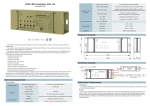
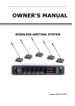
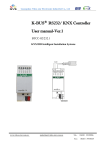
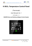
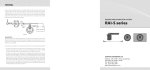
Guangzhou Video-star Electronic Industrial Co. Ltd.
Guangzhou Video-star Electronics Industrial Co., Ltd
K-BUS Colour Touch Panel 3.5’’
User Manual-Version 1.0
CHTF-35/00.1.01
KNX/EIB Smart Home and Building Control System
www.video-star.com.cn
[email protected]
电话:(8620)39338986
Fax: (8620) 39338465
Contents
1. Introduction
The Colour Touch Panel 3.5″ (hereinafter referred to as TFT) is used to display status and control various
devices in the EIB/KNX system. When you touch some graphic button in the TFT operation system, the TFT will
execute a predefined function, such as switch lighting, scene control or blinds/shutter control etc. The TFT can
display frame via LCD and make warning tone compare with common button panel, and the users can operation
the TFT system easily and clearly via interactive interface.
This manual provides detailed technical information about the TFT for users as well as assembly and
programming details, and explains how to use the TFT by the application examples.
The TFT is connected to the bus via the EIB connection terminals and need a 30V DC additional supply
voltage, to assign physical address and configure the software parameter settings, and update the data directly
through an SD card.
The TFT functions are summarized as following:
1. Capacitive touch screen, TFT colour display;
2. Switching, scenes, dimming, curtains control, intelligent scene control and other control functions
3. Time and date display
4. Screensaver options: clock, electronic photo album, gradient black or do not use
5. Configure the database through the PC software, and update data directly via an SD card
6. Customizing the setting of the main interfaces.
2. Technical Parameters
Power Supply
Operating Voltage
Auxiliary power supply
20-30V DC
Bus Current
<12mA
Bus Power Consumption
<360mW
Auxiliary Power Consumption
<6W
Connections
EIB / KNX
Auxiliary power supply
21-30V DC, powered
from BUS
Via bus connection
terminal(black/red)
Via bus connection
terminal(grey/yellow)
Single core 0.2—6.0mm2
Cable cross-section
Multi core 0.2—4mm2
Operating and
Indicating
Red LED and
Programming button
For assignment of the
physical address
Green LED flashing
Indicate the device running normally
Display screen reset button
Restart TFT display system
Temperature
–5 °C ... + 45 °C
Operation
Storage
-25 °C ... + 55 °C
Transport
– 25 °C ... + 70 °C
Environment
Humidity
Design
<93%, except for
dewing
Embedded installation
Installation
Standard 86-box; wall-mounted
Dimensions
86*86mm
Weight
0.25KG
3. Dimensional Diagram and Circuit Diagram
3.1 Dimensional Diagram
3.2 Circuit Diagram
① and ②: auxiliary power supply connection terminals
connection terminals
⑤: SD card slot
③ and ④: KNX/EIB Bus
4. Project Design and Applications
Features Overview:
TFT main interface can be configured according to the users' needs, unrestricted buttons, and max. 10
pages of icons can be configured.
Switching and Dimming
The functions can be used for switching and dimming the lighting devices, the dimming and switching
has feedback status value. Its dimming way uses absolute dimming.
Shutters/blinds Control
The function can be used for movement/lamella adjustment of a blind or a shutter, and the quantity of
devices under control depends on the user.
Scenes Control
The function is used for recalling and storing a scene, and the quantity of devices under control depends
on the user.
Customized Value Sending
The function can be used for sending values of different data type. A group values can be send to bus via
an operation, which include three values that may be different data type. Sending interval can be configured
according to user needs.
Intelligent Scene
User can configure via PC software scene values for different time periods, 24 hours can be divided into
max. 24 time periods, thus user can call different scenes in different time periods.
5. Configuration Software Setting Description
1. Main Interface
2. Functions & Interfaces
6. Interface Effects
Operation Interface and Icon
6.1 Main Control Interface
The main interface shows time and date, page name and functional buttons.
Switch pages by sliding around
6.2 Intelligent Scene Mode
By sliding down from the main interface, it enters the intelligent scene interface; the main interface displays
time and date, the name of scene, and the time setting button.
User can send in different scenarios in pre-set time period, to achieve the purpose of calling different scenarios for
different time.
User can exit Intelligent Scene interface by sliding the screen up, and return to the main interface.
6.3 Time Setting & Time Switch Setting Menu
6.4 Time Setting Interface
Clicking "Time Setting" in Intelligent Scene to enter time setting interface, as shown below:
6.5 Time Switch
Clicking the icon can enable or disable the day timing function of weekly timer.
6.6 Screensaver Clock Interface
6.7 Program Updating Interface
When user inserts the SD card with project file into the slot, it will prompt, as shown below:
7. Functions & Applications
7.1 Switching and Dimming
1. Icon
2.Operation Interface
Short press the button to send the switching telegram
Long press the button for dimming (according to the parameters setting)
See the figure as follows,
7.2 Shutters/blinds Control
1、Icon
2、Operation Interface
Short press the curtain button to enter its secondary interface, showing as follows,
Depending on the configuration of the software parameters, in blinds/curtains mode, two or three
buttons can be invoked;
Long-press button to move up or down the blinds, releasing the button to stop the blinds; (according to
the parameters setting)
Short-press button can move up and down or stop the blinds.
Click the bottom right button to return to a main interface.
7.3 Scenes Control
1. Icon
2. Operation Interface
Short-press to call scenes
Long press to enter the secondary interfaces, asking whether to save the scene (depending on the
parameter settings), showing as the below figure,
Click on the button of showing effect picture, return to the main interface.
7.4 Customized Value Sending
1.Icon
2.Functions
Click the button to send a group of different types of data telegrams. (According to the parameters setting)
7.5 Temperature Control
1. Icon
The top row:
humidity,
cooling,
heating,
speed,
speed status
display;
The middle row:
The bottom row:
mode;
Indoor/outdoor temperature switch
comfortable mode,
temperature setting,
standby mode,
temperature display
night mode,
protection
set displaying temperature value.
2. Functions
Humidity: by bus telegram to update values.
Heating/Cooling: configure temperature control system through the configuration software. If set as
heating/cooling system, user can click to switch between heating and cooling.
Speed: Long press its icon to enter the wind speed setting interface. After setting, the new value will be
updated in the interface. Short-press to switch to OFF, AUTO (if you set the wind speed automatic mode).
Indoor/outdoor Temperature: click the icon to switch to display indoor or outdoor temperature, and users
can set automatic switching time in the configuration software.
Working Modes: user can switch the current mode by clicking the icon.
Temperature Setting: press it to set the current mode temperature range of 5 to 40 degrees Celsius.