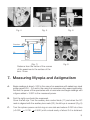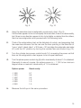
1
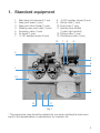
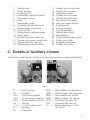
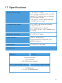
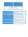
Notification
Dear Users,
Thank you for your purchase of R 2500 Refractor. Please take time to read our
user’s manual carefully before use.
This guarantees you to make full use of this unit and prolongs the operation life of
this unit.
Content
1. Standard Equipment ......................................................................................4
2. Subjective Eye Tester .....................................................................................5
3. Name of Parts ................................................................................................6
4. Details of Auxiliary Lenses ..............................................................................7
5. Measuring Performance .................................................................................8
6. Preparation Before Eye Testing .......................................................................8
7. Measuring Myopia and Astigmatism ...............................................................9
8. Precision Measurements of Astigmatic Axis ..................................................11
9. Precision Measurement of Astigmatic Power ................................................12
10. Precision Measurement of Spherical Power ..................................................12
11. Eye Balance Test ..........................................................................................13
12. Measuring Presbyopia ..................................................................................14
13. Measuring Heterophoria (horizontal) .............................................................15
14. Measuring Heterophoria (vertical) .................................................................16
15. Details of Rotating Near Point Chart .............................................................16
16. Distance Compensation ...............................................................................17
17. Specifications ...............................................................................................19
1. Standard equipment
1.
2.
3.
4.
5.
6.
7.
Main body of instrument (1 set)
Near point scale (1 pce)
Near point chart holder (1 pce)
Rotating near point chart (1 pce)
Accessory case (1 pce)
Air brush (1 pce)
-0.12C auxiliary lenses (2 pcs)
8. -2.00C auxiliary lenses (2 pcs)
9. Silicon cloth (1 pce)
10. Dust cover (1 pce)
11. Sanitary face shields
(1 each right and left)
12. Fitting screw (1 pce)
13. Polystyrene case (1 pce)
10
7
8
9
2
5
6
1
3
13
4
12
11
Fig. 1
* The polystyrene case should be retained for use when sending the instrument
back to the representative or manufacturer for overhaul, etc.
4
2. Subjective Eye Tester
A.
New levelling mechanism
B.
Fingertip adjustment for sphere power control
Just the right figure from 0 to ~19.00D and 0 to +16.75D obtained with light,
fingertip control of the fast feed dial. Optional ±10.00D lenses are also available.
C.
Measuring astigmatism
Readings 0 to - 6.00D, which become possible up to - 8.00D with the accessory
lenses -2.00D. Used in combination with the cross cylinder for precision
measurement.
D.
Cross cylinder (±0.250)
Tests are speeded up by eliminating, the need for axis adjustment, a very efficient
synchronizing mechanism being provided and the loupe is readily turned by means
of the knob.
E.
Rotary prism
The wider 1∆ D spacing in the 20∆ D range simplifies reading and incorporation
into the main body of the instrument means that a maximum field of view is
obtained.
F.
Unique new convergence system mechanism
Convergence lever control for precision near point readings.
G.
Wide range of auxiliary lens combinations (See details on the page 6)
H.
Precision machined to finest tolerances
The use of top quallity bearings and elimination of the need for periodic lubrication.
5
3. Names of Parts
3
4
1
2
23
6
7
5
16
17
18
9
8
32
11
30
20
21
10
29
12
31
13
15
14
19
22
24
25
26
28
27
Fig. 2
6
1
2
3
4
5
6
7
8
9
10
11
12
13
14
15
16
Locking knob
Clamp bracket
Levelling knob
Interpupillary adjustment knob
Convergence lever
Level
Interpupillary scale
Forehead rest adjusting knod
Sphere power control ring
Cross cylinder
Sphere power reading window
Rotary prism
Cylinder lens axis control ring
Cylinder lens power control knob
Cylinder lens axis scale (A)
Sphere power rapid feed dial
17
18
19
20
21
22
23
24
25
26
27
28
29
30
31
32
Auxiliary lens control knob
Auxiliary lens symbols
Astigmatism scale
Cylinder lens axis index
Cylinder lens axis scale
Accessory lens pinhole
Near point scale receiver
Forehead rest
Corneal foresight
Corneal backsight
Sanitary face shield
Main aperture
Cross cylinder rotating knob
Rotary prism knob
Astigmatic axis index
Auxiliary lens mark
4. Details of Auxiliary Lenses
12 Kinds of auxiliary lenses can be set at each main aperture on right and left sides.
Fig. 3
O ...........Open aperture
OC ........Occluder
±.50 ......+0.50 cross cylinder
6∆ U ..... 6 prism diopter base Up
10∆ I .....10 prism diopter hase In
PH .........Pinhole
+ 12 ......+ 0.12D auxiliary lens
PL .........Red filter
GL .........Green filter
RMH .......Red maddox rod, horizontal
WMH ......White maddox rod, horizontal
RMV .......Red maddox rod, vertical
WMV ......White maddox rod, vertical
P135°......Polarizing filter, axis 135°
P45°........Polarizing filter, axis 45°
R ............Retinoscopic lens, +2.00D
(for 50cm)
7
5. Measuring Performance
A.
Provides highly accurate readings over a wide range.
Used in measurements of Myopia, Astigmatism, Hyperopia, Presbyopia,
Heterophoria. Range of Accommodation, Convergence, Aniseiconia, Stereopsis
and Binocular Vision.
B.
Rapid, accurate readings on binocular visual balance
C.
Speedy astigmatism tests
With interlocking mechanism of the cross cylinder lens axis and the cylinder
lens axis control ring, one touch accurate astigmatism readings are now possible.
D.
In short, middle and long distance tests, it is possible to have the optical axis of
the lens and the line of examinee’s vision coincide.
6. Preparation Before Eye Testing
A.
Have the examinee sit on an eye examination chair.
B.
Adjust both readings in the sphere power reding window (11) and astigmatism
scale (19) to 0.00. (Fig. 4)
C.
Adjust the interpupillary scale (7) setting to the interpupillary distance of the
examinee. (Fig. 5)
D.
Level the instrument with the levelling knob (3) while watching the level (6). (Fig, 6)
E.
Align the examinee’s eyes with the right and left main apertures (28) and tighten
the arm fixing knob.
F.
Turn the forehead rest adjusting knob (8) until the scale “0” on the corneal
backsight (26), the corneal foresight (25) and the vertex of the cornea of the
examinee are all in a straight line. (Fig. 7)
8
Fig. 4
Fig. 5
Fig. 6
Examiner
26
0 Position
Examinee
(Fig. 7)
Distance from the vertex of the cornea
of the examinee to the surface of the
lens: 12mm
Fig. 8
7. Measuring Myopia and Astigmatism
A.
Begin readings at about +3.0D in the case of an examinee with naked eye visual
power around 0.5 ~ 0.6 and in the case of an examinee who wears spectacles,
first find the power of the spectacles with a Lensmeter and begin readings with
a figure added + 3.00D to the measured power.
B.
First the right eye should be measured.
Cover the left eye. Turn the auxiliary lens control knob (17) and when the OC
mark is aligned with the auxiliary lens mark (32), the left eye is covered. (Fig. 8)
C.
Turn the sphere power control ring on one side and reduce 0.25D at a time
(+3.00D + 2.75D +2.50D) until a visual acuity of about 0.5 is obtained.
9
Fig. 9
Fig. 10
D.
Have the examinee look at astigmatic visual acuity chart. (Fig. 9)
If all the lines appear to him to be equally thick and dark, there is no abnormality,
but if lines in one direction appear to him to be lighter or darker than the others,
then he has astigmatism and proceed with the following tests.
E.
Think of the astigmatism chart as the dial plate of a clock, and supposing that
the examinee answers that he can see the lines pointing in the direction of
“one o’ clock” clearly, take 1 x 30 times = 30° and align the astigmatic axis index
(31) with the 30° position by turning the cylinder lens axis control ring (13).
F.
Turn the cylinder lens power control knob (14), increasing the power until all
lines on the astigmatism chart appear to be of equal darkness.
G.
Turn the sphere power control ring (9) until a visual acuity of about 1.0 is obtained.
(Example) In case of myopia, the sphere power is — 1.75D to be minimum
degree when a maximum visual acuity of 1.0 is obtained.
H.
Sphere power
Visual acuity
-1.00D
-1.25D
-1.50P
-1.75D
-2.00D
-2.25D
0.7
0.8
0.9
1.0
1.0
1.0
Measure the left eye in the same procedure.
10
8. Precision Measurement of
Astigmatic Axis
A.
Set the cross cylinder (10) at the main aperture.
B.
Turn the periphery of the cross cylinder to adjust the axis of the cross cylinder
rotating knob (29) in the same direction as astigmatic axis (7-E) and set it at
click-stop position.
C.
Now have the examinee look at visual acuity charts about two steps lower than
those which he has been able to see. For example, if he has been able to read
those at 1.0 point, now have him look at those for 0.8.
D.
Turn surfaces 1 and 11 of the cross cylinder (10) alternately and have the examinee
look at them. If both surfaces can be seen equally well, there is no abnormality,
but if one is more clearly seen than the other, carry out the following procedure.
E.
Stop turn at the surface which is clearly seen, next move and shift the astigmatic
axis 5° in the direction of red dots on the cross cylinder by the cylinder lens axis
control ring (13).
F.
When surfaces I and II can both be seen equally well after this; method is used
and tests repeated two or three times, it is determination of an astigmatic axis.
Fig. 11
Fig. 11A
Fig. 12
11
9. Precision Measurement of Astigmatic
Power
A.
Turn the periphery of the cross cylinder to adjust the axis of the P marks in the
same direction as astigmatic axis and set it at click-stop position.
B.
Turn surface I and II alternately and have the examinee look at them.
If both surfaces can be seen equally well, there is no abnormality, but if one
is more clearly seen than the other, carry out the following procedure.
C.
Stop turn at the surface which is clearly seen. Then if the P marks align with the
red dots, add astigmatic power -0.25D by turning the cylinder lens power control
knob (14), and if the P marks align with the black dots, decrease astigmatic
power -1.25D.
D.
And again turn surfaces I and II of the cross cylinder, and repeat procedures
from (B). When both surfaces can be seen equally well, it is determination of an
astigmatic axis.
E.
Measure the left eye in the same procedure and after finished, move the cross
cylinder from the main aperture.
10. Precision Measurement of Spherical Power
A.
For fine adjustment of the spherical power, first the right eye should be measured
with occlusion of the left eye.
B.
Have the examinee look at both the red and green tests on the visual acuity chart
and have him compare clearness of the black + in the red andgreen tests.
If the + in both tests can be seen equally well, it shows that the corrected power
is actually correct, but if either of these colors can be seen well, carry out the
following procedure.
C.
If the red can be seen well, increase the reading in the sphere power reading
window (11) by -0.25D, and if the green can be seen well, increase the reading
by +0.25D. Continue to make adjustments until both red and green tests can
be seen equally well.
D.
Have the examinee look at the visual acuity chart and try to obtain a maximum
visual acuity that he can read.
12
E.
Have the examinee lock at a teat where the maximum visual acuity has been
obtained, and add spherical power by +0.25D.
F.
If the test is out of focus, restore the spherical power to the former reading and
measurements are finished now, but if in focus, carry out the following procedure.
G.
Add more +0.25D and restore the spherical power where the test has been out
of focus to the former reading, and measurements are finished now.
H.
Measure the left eye in the same procedure.
11. Eye Balance Test
A.
Have the examinee look at about 0.7 point on the visual acuity chart.
B.
Set the rotary prisms (12) at the right and left main apertures (28) (Note: the rotary
prism knobs (30) should be set at click-stop position on the ears’ side of the
examinee). Next, insert a 2∆ DBU prism in the left and a 2∆ DBD in the right.
(See Fig. 13)
(The visual line from the left eye moves in the lower direction and that from the
right eye moves in the upper direction.)
C.
When the examinee looks at the test chart with binocular vision, he can see it
split into two, an upper and a lower: i.e. the lower part in the left eye and the
upper part in the right eye. If both upper and lower parts can be seen equally
well, it shows that the right and left eyes are balanced. If either of the upper and
lower parts can be seen well, carry out the following procedure.
D.
Add +0.25D at a time to the spherical power for the eye where the test chart
has been able to be seen well until both eyes can balanced.
If balance can not be obtained, try to improve the visual acuity of the dominant eye.
Fig. 13
13
12. Measuring Presbyopia
A.
Make perfect correction of the refraction anomaly in distant vision and make a
setting of the instrument based on the result.
B.
Set a ±0.50 auxiliary cross cylinder lens in place for each eye.
C.
Turn the convergence levers (5) inward.
D.
Set a near point chart in a fixed place of the instrument.
E.
Allow the examinee to choose the distance at which the chart is set up, and
select a cross-cylinder grid on the near point chart.
Cross-cylinder grid (Fig. 14)
F.
Have the examinee look at the cross-cylinder grid with both eyes to compare
darkness of the vertical and horizontal lines.
For a presbyope (a range of accommodation is smaller), usually the horizontal
lines will be seen darker.
G.
Add the sphere powers in both the right and left sphere power reading windows
+0.25D at a time simultaneously and stop this procedure when both the vertical
and horizontal lines are seen equally well.
Now the spherical power for near point is determined.
H.
The value taken the distance sphere from the near point sphere is an ADD power.
This is required for checking clearness at intermediate distance or prescription
of a continuous vision lens.
14
13. Measuring Heterophoria (Horizontal)
A.
Project a fixation light (a point light) or a fixation point from the projector at a
distance.
B.
Insert the RMH auxiliary lens for the right eye and the O (open) for the left eye.
C.
When seen with the right eye, the image appears as in Fig.16, and when seen
with the left eye, a point light appears as in Fig.15.
Left eye (Fig. 15)
D.
Right eye (Fig. 16)
If there is no phoria when seen with both eyes, the two images appear as in Fig.17.
If there is a horizontal phoria, the two images appear disaligned as in Fig.18
and Fig.19.
(Fig. 17)
(Fig. 18)
(Fig. 19)
E.
If there is a horizontal phoria, set the rotary prism for the left eye at click-stop
position in the horizontal phoria measuring direction.
F.
Turn the rotary prism knob slowly until the two images are aligned as in Fig.17.
The scale reading when both aligned is a degree of the horizontal phoria.
15
14. Measuring Heterophoria (Vertical)
Measured in the same procedure as above with use of the RMV auxiliary lens.
If used with the WMH and WMV auxiliary lenses for the left eye, also measured in the
same procedure.
15. Details of Rotating Near Point Chart
The standard examination distance for this near point chart is 40cm (but, the No.12
test should be used at a distance of 70cm).
1.
2.
3.
4.
5.
6.
Sentences (0.4 - 1.0)
Alphabetical letters (0.5 - 1.0)
Cross-cylinder grid (thin lines)
Sentence
Alphabetical letters
Astigmatic chart
7.
8.
9.
10.
11.
12.
Sentences (0.1 - 0.3)
Alphabetical letters (0.1 - 0.4)
Cross-cylinder grid (thick lines)
Vertical row of sentence
Alphabetical letters
Intermediate distance chart
(at an examination distance of 70cm)
16
16. Distance Compensation
If the distance between the instrument and the examinee is not as specified, distance
compensation should be carried out (See 6 - (F), Fig. 7).
When the Sphere power is Plus (+):
If the distance is shorter, (-) compensation
If the distance is longer, (+) compensation When the Sphere power is Minus (-) :
If the distance is shorter, (+) compensation
If the distance is longer, (-) compensation
(Example)
If with a sphere power reading of +10.00 the distance is 5mm longer than specified,
a correction should be 0.52 according to the compensation table, making +10.52D
(+10.00 + (+0-52) = + 10.52).
Distance Compensation Table (with + Sphere)
PHOROPTOR
Reading
+ 1.00
+ 2.00
+ 3.00
+ 4.00
+ 5.00
+ 6.00
+ 7.00
+ 8.00
+ 9.00
+ 10.00
+ 11.00
+ 12.00
+ 13.00
+ 14.00
+ 15.00
+ 16.00
Distance
1mm 2mm
001 002
004 008
01
02
02
03
03
05
04
07
05
10
06
13
08
16
10
20
12
25
15
30
18
35
21
41
24
47
27
53
3mm
003
01
03
05
07
10
14
19
24
30
37
45
53
62
71
81
4mm
004
02
04
07
11
16
21
27
34
42
51
61
72
84
97
1.11
5mm
005
02
05
08
12
18
25
33
42
52
64
77
91
1.06
1.22
1.39
6mm
006
02
06
10
15
21
29
39
51
64
78
93
1.10
1.29
1.49
1.71
7mm
007
03
07
12
18
26
36
48
61
75
91
1.10
1.31
1.53
1.77
2.03
8mm
008
03
08
13
21
31
42
55
70
87
1.06
1.27
1.51
1.77
2.05
2.35
9mm
009
04
09
15
24
35
48
64
81
99
1.21
1.46
1.73
2.03
2.36
2.71
10mm
01
04
10
17
26
38
52
70
90
1.11
1.36
1.64
1.95
2.29
2.67
3.07
17
Distance Compensation Table (with - Sphere)
PHOROPTOR
Reading
- 1.00
- 2.00
- 3.00
- 4.00
- 5.00
- 6.00
- 7.00
- 8.00
- 9.00
- 10.00
- 11.00
-12.00
-13.00
-14.00
-15,00
-16.00
-17.00
-18.00
-19.00
Distance
1mm 2mm
001 002
01
01
01
02
02
03
03
05
04
07
05
10
06
13
08
16
10
20
12
24
14
28
16
33
19
38
22
43
25
49
28
55
31
62
35
69
3mm
003
02
03
05
07
10
14
19
24
30
36
42
48
55
63
72
81
91
1.02
4mm
004
02
04
06
10
15
20
25
31
38
46
55
64
74
85
96
1.08
1.2]
1.34
5mm
005
02
04
08
12
17
24
31
39
48
57
67
78
90
1.03
1.17
1.32
1.48
1.65
6mm
006
03
05
09
15
22
30
38
47
57
68
80
94
1.08
1.23
1.39
1.56
1.74
1.93
7mm
007
03
06
11
17
25
33
42
53
65
79
93
1.08
1.24
1.41
1.60
1.80
2.0)
2.25
8mm
008
03
07
12
19
28
38
49
61
74
88
1.04
1.22
1.41
1,61
1.82
2.04
2,27
2.51
9mm
009
04
08
14
22
31
42
54
67
82
99
1.17
1.36
1.56
1.78
2.01
2.25
2.50
2.77
10mm
01
04
09
15
24
35
47
60
74
90
1,08
1,28
1.49
1.71
1.95
2.20
2.46
2.73
3.02
18
17. Specifications
Sphere powers range
+ 16.75D to -19.00D,
with minimum reading 0.25D or 0.12D
(when 0.12D auxiliary lens or optional
±0.12D lens is in use)
+ 26.75D to -29.00D (when optional
+10.00D lens is in use)
Cylinder powers range
0 to -6.00D, with minimum reading
0.25D or 0.12D
(when auxiliary lens is in use)
0 to -8.00D (when -2.00D auxiliary lens
is in use)
Astigmatic axis scale
0 to 180° in 5° steps
Cross cylinder
±0.25D, reversal type
(synchronized with astigmatic axis)
±0.50D optional
Rotary prism
0 to 20∆ D in 1∆ D step
Auxiliary lens
Right eye
Left eye
O (Open aperture)
OC (Occluder)
+50 (Fixed cross cylinder)
6∆ U (6 prism dioter base Up)
10∆ I (10 prism diopter base In)
PH (Pinhole)
+ 12 (+0.12D sphere lens)
19
RL (Red filter)
RMH (Red maddox rod,
horizontal)
RMV (Red maddox rod,
vertical)
GL (Green filter)
WMH (White maddox rod,
horizontal)
WMV (White maddox rod,
vertical)
P45°(Polarizing filter, axis 45°)
P135°(Polarizing filter, axis 135°)
R (Retinoscopic lens. +2.00D, for 50cm)
Interpupillary adjustment
48mm to 80mm in 1mm step (right and
left synchronized)
Forehead rest adjustment
16mm backward and forward
Convergence
The optical axes of the lenses are
aligned at a distance of 400mm from
the vertexes of the corneas (2mm each
for right and left inward) Interpupillary
distance enabling convergence = 57mm
to 80mm
Corneal distance device
2mm forward and 5mm backward from
standard plane; with scale
Effective field of view
19mm
20
LUXVISION is not responsible or liable for indirect, special or consequential damages arising out of or in
connection with the use or performance of the product or damages with respect to any economic loss,
loss of property, loss of revenues or profits, loss of enjoyment or use, costs of removal or installation or
other consequential damages of whatsoever nature. Some states do not allow the exclusion or limitation
of incidental or consequential damages. Accordingly, the above limitation may not apply to you.
Every effort has been made to ensure the accuracy of this manual. However, LUXVISION, makes no
warranties with respect to the documentation and disclaims any implied warranties of merchantability
and fitness for a particular purpose. LUXVISION, Inc. shall not be liable for any errors or for incidental or
consequential damages in connection with the furnishing, performance, or use of this manual or the examples
herein. The information in this document is subject to change without notice.
21