1
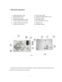
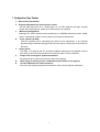
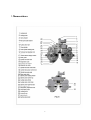
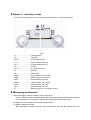
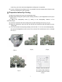
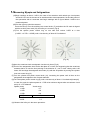
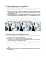
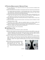
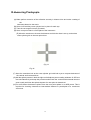
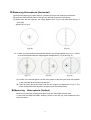
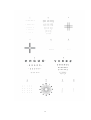
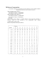
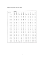
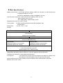
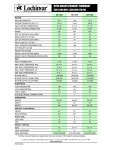
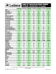
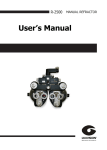
USER'S MANUAL
-1-
MANUAL REFRACTOR
Thank you for your taking MANUAL REFRACTOR this time.
This MANUAL REFRACTOR is c ompac tlydesigned to make accurate
measurements of complicated
Visual functions. You are required to read this manual carefully in order to become
familiar with features and structures of this instrument..
Special Attention
.This is a precision instrument and should be handled carefully.
.The plastic dust cover should be used whenever the instrument is not use.
.The instrument should not be used or left in a hot and humid or dusty place.
.Do not break up the instrument as sufficient optical adjustments have been made o it at
factory.
.Remove dust off the lens with an air brush. If the lens should have been smeared with
Fingerprints, wipe it clean with a fresh cloth softly.
.We would recommend you to have the lenses cleaned by a specialist yearly.
-2-
Table of Contents
⒈ Standard equipment ……………………………………………………….2
⒉ Subjective eye tester……………………………………………………….3
⒊ Nomenclature…………………………………………………………….....4
⒋ Detail of auxiliary lenses…………………………………………….……..5
⒌ Measuring performance……………………………………………………5
⒍ Preparation before eye testing ……………………………………… …..6
⒎ Measuring myopia and astigmatism……………………………………. .7
⒏ Precision measurements of astigmatic axis……………………………..8
⒐ Precision measurements of astigmatic power…………………………. 8
⒑ Precision measurements of spherical power…………………………….9
⒒ Eye balance test…………………………………………………………….9
⒓ Measuring presbyopia …………………………………………………….10
⒔ Measuring heterophoria(horizontal)………………………………………10
⒕ Measuring heterophoria(vertical) …………………………………………11
⒖ Details of rotating near point chart………………………………………..11,12
⒗ Distance compensation table… ………………………………………...13,14
⒘ Main specifications…………………………………………………………15
-3-
⒈Standard equipment
1.
2.
3.
4.
5.
6.
7.
Near point scale ( 1 pce)
Main instrument(1 set)
Fitting screw (1 pce)
Near point chart holder ( 1 pce)
-0.12C auxiliary lenses (2 pcs)
-2.00C auxiliary lenses (2 pcs)
Accessory case (1 pce)
8.
9.
10.
11.
12.
13.
14.
Silicon cloth (1 pce)
Rotating near point chart (1 pce)
Dust cover (1 pce)
Air brush (1 pce)
Lens cleaning fluid (I pce)
Glasses cloth
Instruction manual
The polystyrene case should be retained for use when sending the instrument back to the
distributor or manufacturer for overhauled.
-4-
⒉ Subjective Eye Tester
A New leveling mechanism
B Fingertip adjustment for sphere power control
Just the right figure from 0 to -19.00D and 0 to +16.75D obtained with light, fingertip
control of the fast feed dial. Optional ±10.00D lenses are available.
C Measuring astigmatism
Readings 0 to -6.00D, which become possible up to -8.00Dwith accessory lenses -2.00D ,
Used in combination with the cross cylinder for precision measurement.
D
Cross cylinder (±0.25D)
Tests are speeded up by eliminating the need for axis adjustment, a very efficient
Synchronizing mechanism being provided and the loupe is readily turned by means of
the knob.
E Rotary prism
The wider 1 D spacing the 20 D range simplifies reading and incorporation into the
main body of the instrument means that a maximum field of view is obtained.
F
Unique new convergence system mechanism
Convergence lever control for precision near point readings.
G
Wide range of auxiliary lenses combinations (See details on the page 6)
H
Precision Machined to finest tolerances
The use of top quality bearings and elimination of the need for periodic lubrication
5
⒊ Nomenclature
6
⒋ Details of
Auxiliary Lenses
12 Kinds of auxiliary lenses can be set at each main aperture on right and left sides.
(fig.3)
O…………………………Open aperture
OC.................................Occluder
±0.50……………………±0.50 cross cylinder
6 U……………………6 prism diopter base Up
10 I …………………..10 prism diopter base In
PH………………………Pinhole
+0.12…………………. +0.12D auxiliary lens
PL………………………Red filter
GL………………………Green filter
RMH……………………Red maddox rod, horizontal
WMH……………………White maddox rod,vertical
RMV…………………….Red maddox rod,vetical
WMV…………………….White maddox rod, vertical
P135°……………………Polarzing filter, axis 135°
P45°..............................Polarizing filter, axis 45°
R …………………….Retinoscopic lens, +2.00D (for 50 cm)
⒌ Measuring performance
(A)Provides highly accurate readings over a wide range.
Used in measurements of Myopia,Astigmatism,Hyperopia,Presbyopia.Hrterophoria,Range
of Accommodation, Convergence, Aniseiconia,Stereopsis and Binocular Vision.
(B) Rapid, accurate readings on binocular visual balance.
(C) Speedy astigmatism tests
With interlocking mechanism of the cross cylinder lens axis and the cylinder lens axis
7
control ring, one touch accurate astigmatism readings are now possible.
(D) In short, middle and long distance test, it is possible to have the optical axis of the lens and
the line of examinees`s vision coincide.
⒍ Preparation before Eye Testing
(A) Have the examinee sit on an eye examination chair.
(B) Adjust both readings the sphere power reading window (11) and astigmatism scale (19) to
0.00 ( Fi9. 4)
(C) Adjust the interpupillary scale (7) setting to the interpupillary distance of the
examinee.(Fig.5)
(D) Level the instrument with the leveling knob (3) while watching the level (6).( Fig.6)
(E) Align the examinee`s eyes with the righ and left main apertures (28) and tighten the arm
fixing knob.
(F) Turn the forehead rest adjusting knob(8) until the scale “O” on the corneal backsight(26),,
the corneal foresight(25) and the vertex of the cornea of the examinee are all in a straight
line.(Fig.7)
(Fig.5)
(Fig.4)
(Fig.6)
Distance form the vertex of
the cornea of the examinee
to surface of the lens:12mm
(Fig.7)
(Fig.8)
8
⒎ Measuring Myopia and Astigmatism
(A)Begin readings at about +3.0D in the case of an examinee with naked eye visual power
around 0.5~0.6 and in the case of an examinee who wears spectacles, fist find the power of
the spectacles with a Lensmeter and begin readings with a figure added +3.00D to the
measured power.
(B)First the right eye should measured.
Cover the left eye.Turn the auxiliary lens control knob (17) and when the OC mark is aligned
with the auxiliary lens mark (32), the left eye is covered. (Fig.8)
(C)Turn the sphere power control ring on one side and reduce 0.25D at a time
(+3.00D→+2.75D→+2.50D) until a visual acuity of about 0.5 is obtained.
(Fig.9)
(Fig.10)
(D)Have the examinee look at astigmatic visual acuity chart (Fig.9)
(E)Think of the astigmatism chart as the dial plate of a clock ,and supposing that the examinee
answers that he cn see the lines pointing in the direction of “ one 0` clock” clearly, take 1×30
times =30°and align the astigmatic axis index (31) with the 30°position by turning the cylinder
lens axis control ring(13)
(F)Turn the cylinder lens power control knob (14), increasing the power until all lines on the
astigmatism chart appear to be of equal darkness.
(G)Turn the sphere power control ring (9) until a visual acuity of about 1.0 is obtained.[example]
In case of myopia, the sphere power is -1.75D to be minimum degree when a maximum visual
acuity of 1.0 is obtained.
Sphere power
Visual acuity
-1.00D
0.7
-1.25D
0.8
-1.50D
0.9
-1.75D
1.0
-2.00D
1.0
-2.25D
1.0
(H) Measure the left eye in the same procedure.
9
⒏ Precision Measurement of Astigmatic Axis
(A)Set the cross cylinder (10) at the main apreture.
(B)Turn the periphery of the cross cylinder to adjust the axis of the cross cylinder rotating knob
(29) in the same direction as astigmatic axis (7-E) and set it at click-stop position.
(C)Now have the examinee look at visual acuity charts about twosteps lower than those which
he has been able to see.For esample, if he has been able to read at 1.0 point, now have
him look at those for 0.8.
(D)Tuan surfaces and of the cross cylinder(10) alternately and have the examinee look at
them. If both surfaces can be seen equally well, there is no abnormality,but if one is mire
clearly seen than the other, carry out the following procedure.
(E)Stop turn at the suface which is clearly seen,next more and shift the astigmatic axis 5°in the
direction of red dots on the cross cylinder by the cylinderlens axis control rinf(13)
(F)When surfaces
and can both be seen equally well after this method is used and tests
repeated two or three times. It is determination of an astigmatic axis.
(Fig.11)
(Fig.11A)
(Fig.12)
⒐ Precision Measurement of Astigmatic Power
(A)Turn the periphery of the cross cylinder to adjust the axis of the P marks in the same direction
as astigmatic axis and set it at click-stop position.
(B)Turn surface and
alternately and have the examinee look at them.
If both surfaces can be seen equally well, there is no abnormality,but if one is moreclearly
seen than the other,carry out the following procedure.
(C)Stop turn at the surface which is clearly seen. Then if the P marks align with the red dots,add
astigmatic power -0.25D by turning the cylinder lens power control knob(14), and if the P
marks align with the black dots,,deccrease astigmatic power -0.25D.
(D)And again turn surfaces and of the cross cylinder, and repeat procedures from (B).When
both surfaces can be seen equally well, it is determination of an astigmatic
Axis.
(E)Measure the left eye in the same procedure and after finished,move the cross cylinder from
the main aperture.
10
⒑
Precision Measurement of Spherical Power
(A)For fine adjustment of the sphercal power,first the right eye should be measured with
occlusion of the eye.
(B)Have the examinee look at both the red and green tests on the visual acuity chart and have
him compare clearness of the black + in the red andgreen tests. If the + in both tests can be
seen equally well, it shows that the corrected power is actually correct,but if either of there
colors can be seen well ,carry out the following procedure.
(C)If the red can be seen well,increase the reading in the sphere power reading window (11) by
_0.25D, and if the green can be seen well,increase the reading by +0.25D.Continue to
make adjustments until both red and green tests can be seen equally well.
(D)Have the examinee look at the visual acuity chart and try to obtain a maximum visual acuity
that he can read.
(E)Have the examinee look at teat where maximun visual acuity has been obtained, and add
spherical power by +0.25D.
(F)If the test is out of focus, restore the spherical power to the former reading and
measurements are finished now, but if in focus,carry out the following procedure.
(G)Add more +0.25D and restore the spherical power where the test has been out of focus to
the former reading, and measurements are finished now.
(H)Measure the left eye in the same procedure.
⒒ Eye Balance Test
(A)Have the examinee look at about 0.7 point on visual chart.
(B)Set the rotary prisms(12) at the right and left main apertures (28) (N0TE:the rotary prism
knobs (30) should be set at click-shop position on the ears` side of the examinee.).Next,
insert a 2 DBU prism in the left and a 2 DBU in the right. (see Fig.13)(The visual line
from the left eye moves in the lower direction,he can see it split into two,
(C)When the examinee looks at the test chart with binocular vision,he can see it split into two,an
upper and lower:i.e. the lower part in the left eye and the upper part in the right eye,If both
upper and lower parts can be seen equally well,it shows that the right and left eyes are
balanced.I f either of the upper and lower parts can seen well ,carry out the following
procedure.
(D)Add +0.25D at a time to the spherical power
for the eye where the test chart has been
able to be seen well until both
eyes
can balanced.If balance can not be obtained,
try to improve the visual acuity the dominant
eye.
(Fig.13)
11
⒓ Measuring Presbyopia
(A) Make perfect correction of the refraction anomaly in distant vision and make a setting of
the
instrument based on the resuit.
(B) Set a ±0.50 auxiliary cross cylinder lens in place for each eye.
(C) Tuan the convergence levers (5) inward.
(D) Set a near point chart in a fixed place of the instrument.
(E) Allow the examinee to choose the distance at which the chart is set up, and seleca
cross-cylinder grid on the near point chart.
(Fig.14
Fig.14
(F) Have the examinee look at the cross-cylinder grid with both eyes to conpare darkness of
the vertical and horizontal lines.
(G)Add the sphere powers in both the right and left sphere power reading windows +0.25D at a
time simultaneously and stop this procedure when both the vertical and horizontal lines are
seen equally well.Now the spherical power for near point is determined.
(H)The value taken the distance sphere from the near point sphere is an ADD power. This is
required for checking clearness at intermediate distance or prescription of a continuous
vision lens.
12
⒔ Measuring Heterophoria (Horizontal)
(A) Project a fixation light (a point light) or a fixation point from the projector at a distance.
(B) Insert the RMH auxiliary lens for the right eye and the O (open) for the left eye.
(C) When seen with the right eye, the image appears as in Fig.16. and when with left eye, a
point light
appears as in Fig.15.
(Fig.15)
(Fig.16)
D If there is no phoria when seen with both eres,the two images appear as in Fig.17. If there
is a horizontal phoria,the two image appear disaligned as in Fig.18 and Fig.19.
(Fig.17)
(Fig.18)
(Fig.19)
(A) If there is a horizontal phoria, set the rotary prism for the left eye at click-stop position
in the horizontal phoria measuring direction.
(B) Tuan the rotary pria knob slowly until the two images are aligned as in Fig.17. The
scale reading when both aligned is a degree of the horizontal phoria.
⒕ Measuring
Heterophoria (Vertical)
Measured in the same procedure as above with use of the RMV auxiliary lens.
If used with the WMH and WMV auxiliary lenses for the left eye, also measured in the
same procedure.
13
⒖ Details of Rotating Near Point Chart
The standard examination distance for this near point chart is 40cm
1.
2.
3.
4.
5.
6.
Direction
Alphabetical letters(0.5-1.0)
Cross-cylinder grid (thin lines)
Cross-cylinder grid (thick lines)
Alphabetical letters
Alphabetical letters
7. Direction (0.1-0.3)
8.Alphabetical letters (0.1-0.4)
9. Alphabetical letters
10. Astigmatic chart
11.Vertical row of letters
12.Vertical row of letters
14
15
⒗ Distance Compensation
If the distance between the instrument and the examinee is not as specfied ,distance
compensation should be carried out (See 6-(F),Fig.7)
When the Sphere power is Plus (+):
If the distance is shorter ,(-) compensation
If the distance is longer ,(+) compensation
When the Sphere power is Minus (-):
If the distance is shorter ,(+) compensation
If the distance is longer ,(-) compensation
[Example]
If with a sphere power reading of +10.00the distance is 5mm longer than specified, a
correction should be 0.52 according to the compensation table ,making
+10.52D(+10.00+(+0.52)=+10.52
Distance Compensation Table (with +Sphere)
16
Distance Compensation Table (with -phere)
17
⒘ Main Specifications
Sphere powers range: +16.75D,with minimum reading 0.25D or 0.12D (when +0.12D auxiliary lens
or optical ±0.12Dlens is in use)
+26.75D to -29.00D(when optical ±10.00Dlens is in use)
Cylinder powers range:0 to -6.00D, with minimun reading 0.25D or 0.12D
(when auxiliary lens is in use)
0 to -8.00D (when -2.00D auxiliary is use)
Astigmatic axis scale: 0 to 180°in 5°steps
Cross cylinder : ±0.25D, reversal type(synchronized with astigmatic axis)
±0.50D optical
Rotary prism
: 0 to 20 Din 1 step
Auxilisry
:
Right eye
Left eye
O (0pen aperture)
OC (Occluder)
±0.50(Fixed cross cylinder)
6 U (6 prism dioter base Up)0
10
I (10 prism diopter base In)
PH (Pinhole)
+0.12 (+0.12D sphere lens)
RL(Red filter)
RMH (Red maddox rod, horizontal)
RMV(Red maddox rod, vertical)
GL(Green filter)
WMH(White maddox rod,horizontal)
WMV(White maddox rod,vertical)
P 45°(Polarizing filter, axis 45°)
P 135°(Polarizing filter, axis135°)
R(Retinoscopic lens.+2.00D,for 50cm)
Interpupillary adjustment: 48mm to 80mm in 1mm steo (right and left synchronized)
Forehead rest adjustment: 16mm backward and forward
Convergence
:The optical axces of the lenses are aligned at a distance of 400mm from
the vertexes of the corneas(2mm each for right and left inward)
Corneal distance device: 2mm forward and 5mm backward from standard plane; with scale
Effective field of view: 19mm
18