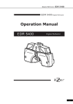
1
-CONTENTS1. IMPORTANT NOTICE .......................................................................... 1
2. SPECIAL ABILITY .............................................................................. 1
3. REQUIRED ATTENTIONS...................................................................... 1
4. SAFETY INFORMATION
4-1. USING ENVIRONMENT ................................................................. 2
4-2. SYMBOL FOR SAFETY ................................................................. 2
4-3. GENERIAL SAFETY INFORMATION .................................................. 2
5. STRUCTURES AND FUCTIONS OF THIS EQUIPMENT
5-1. HEAD ..................................................................................... 4
5-2. A CONSTRUCTION OF A CONTROL KEY-BOARD AND SWITCHES
......... 5
6. CONNECTING AND WORKING THE SYSTEM
6-1. INSTALLATION ......................................................................... 13
6-2. REF/KERATOMETER DATA INPUT ................................................. 14
7. SETTING UP
7-1. OPTOMETRY BY A STANDARD PROGRAM ....................................... 14
7-2. SETTING UP DATE AND TIME ...................................................... 15
7-3. SETTING UP A CONNECTION WITH A CHART PROJECTOR .................. 16
7-4. SETTING UP A CONNECTION WITH A REF/KERATOMETER .................. 16
7-5. SETTING UP SPH ..................................................................... 17
7-6. SETTING UP CYL .................................................................... 17
7-7. SETTING UP AXIS ..................................................................... 18
7-8. SETTING UP PF ....................................................................... 18
7-9. SETTING UP SPEED .................................................................. 19
7-10. SETTING UP COMMUNICATION SPEED ......................................... 19
7-11. SETTING UP TIME FOR SCREEN SAVER ........................................ 20
7-12. SETTING UP OTHERS .............................................................. 21
8. BEFORE CALLING TO SERVICE ENGINEER ............................................. 22
9. COMPOSITIONS .............................................................................. 23
10. SPECIFICATION ............................................................................. 24
EZER
EDR-5200
1. IMPORTANT NOTICE
This equipment can be wrong operated by equipments that generate electromagnetic
wave (mobile phone, radiotelegraph, remote-controlled things etc). Please pull apart
them from this equipment.
When this manual is issued, all information in this manual are confirmed and
concluded carefully. But EZER is not responsible for the mistake or oversight of using
this manual.
EZER can correct, improve and reform the product or its specification on EZER own
sole authority without any notice whenever have to do. And then, this manual may not
contain those alterations sometimes.
EZER hold the right of owner-ship of this manual.
According to a copyright law, no one can copy a part or whole of this manual without
a prior and written consent from EZER.
2. SPECIAL ABILITY
(1) This equipment can measure an error of a refraction of an eye.
- It can control and measure PD.
- LCD monitor displays current situation.
- It can alter to several kinds of units
- You can see and check a VD (Vertex Distance) on VD window.
- You can input an objective data through an external connective terminal.
(2) You can measure easily with a control key-board.
(3) You can connect this equipment with a ref/keratometer and a chart by data cable.
(4) It has a function for convergence. So you can do a close test (short distance test).
3. REQUIRED ATTENTIONS
(1) Before using this, check and make a level of the equipment in advance. If it’s out
of a horizontal, the measurement result could be incorrect.
(2) Be careful to do not drop or give a shock this equipment. The equipment could be
damaged.
(3) When you use this equipment in a place where is strong light, like sunshine, the
measurement result could be incorrect. So please use this in a place where you
can control its light, such as a test room or somewhere.
(4) Do not use any alcohol, thinner, benzene to clean this equipment. The equipment
EZER
1
EZER
(5)
(6)
(7)
(8)
EDR-5200
can be damaged.
If there’s a sudden change of temperature around this equipment, there could be
some dewdrops on this equipment. Then please use after disappearing them all.
If you want to try to use this equipment to connect with other equipments or
instruments, please contact to whom you bought this equipment from and ask
them in advance.
Please keep clean the test part. If there are some finger marks, dust or something,
they could influence the measurement.
If there’s any smell, smoke or noise, separate the power cable from a wall outlet
and call to service engineer or your distributor.
(9) Please separate the electric wire from a wall outlet and put a dust cover on it
during do not use this equipment for a long time.
4. SAFETY INFORMATION
4-1. USING ENVIRONMENT
(1) This equipment should be used in a place where’s clean and no chemical
substances or inflammable either.
(2) Do not use this equipment in a place where’s hot and humid too much.
- Proper temperature for using: 10℃ ~ 40℃
- Proper humidity for using
: 30% ~ 75%
(3) Do never use any volatile liquid to clean the exterior of this equipment.
(4) Do not disassemble or get shocked this equipment for any purpose.
4-2. SYMBOL FOR SAFETY
SYMBOL
DESCRIPTION
Attention, consult ACCOMPANYING DOCUMENTS
4-3. GENERIAL SATETY INFORMATION
If you find the WARNING or the CAUTION as below, please do as this manual says.
You must read and understand this manual enough before using this equipment.
While operate this equipment, unless taking care of those sign, troubles and
accidents could occur.
This manual should be placed in the user’s sight.
CAUTION SIGN
DESCRIPTION
EZER
2
EZER
EDR-5200
The mark is that a danger could happen, unless be careful.
WARNING
You or the other person could be injured seriously.
The mark is that a danger could happen, unless be careful.
CAUTION
You or the other person could be injured slightly and the
equipment could be damaged too.
To emphasize the basic information.
NOTE
To avoid using inappropriately, please read this information
carefully.
Unless use this equipment in a standard power source, a fire or
WARNING
an electric shock can happen.
Must connect or separate the electric wire after switching off the
WARNING
main power. Never operate this equipment with a wet hand or can
be injured by a serious electric shock.
Never disassemble or try to modify this equipment yourself or a
fire, an electric shock can happen.
WARNING
There are some dangerous parts inside of this equipment.
Touching those parts can make you to be injured or die.
Please switch off the main power and separate the electric wire
from AC socket when the symptoms as belows occur.
WARNING
• when it is smoky, smelling, noisy,
• when slop any liquid or drop any metal into the equipment,
• when drop this equipment or case’s broken.
To reduce the electric shock, please connect the cable into the
CAUTION
grounded AC socket all the time.
Because the head of the equipment is heavy, it should be fixed
CAUTION
strongly, or a subject person could be damaged.
When
its first
operation,
it
would
perform
an inspection
automatically. Then, please keep a safe distance the subject
CAUTION
person from the equipment. Especially, be careful and watch not
to get his fingers or something caught in the equipment.
5. STRUCTURES AND FUCTIONS OF THIS EQUIPMENT
5-1. HEAD
EZER
3
EZER
EDR-5200
Front side
Back side
① Swivel Clip : Used by fix the Swivel Unit.
② Swivel Unit : Used by fix the Rod of Short Distance Chart.
③
④
⑤
⑥
⑦
Forehead rest controller : Used by move the Forehead Rest forward.
VD control window : Used to check the patient’s VD.
Level controller grip : Used to control a level.
A level : Used to verify that the refractor head is level.
Forehead rest : Patient’s forehead should the rest during measurement.
Clean it before measurement.
⑧ Measuring Windows : Patient look at the chart through these windows.
⑨ PD control scale
5-2. A CONSTRUCTION OF A CONTROL KEY-BOARD AND SWITCHES
EZER
4
EZER
EDR-5200
A. DISPLAY
INDICATE SPH, CYL, AXIS.
EZER
5
EZER
EDR-5200
B. CONTRAST ADJUSTMENT KNOB
Located in the lower of the body, used to contrast in the display.
C. CHART KEY
Used to choose a chart.
D. MASK KEY
Used when mask the chart. When push the chart key, the mask
will disappear. With cross mask, vertical mask, single mask the
EZER
6
EZER
EDR-5200
measurement will be indicated on the display.
D-1.
: The switch is to mask the chart from the top to the bottom.
When the mask on the chart already, use it just to push the mask
up & down.
D-2.
: This is used to separate the perpendicular line from the chart.
This is used to move perpendicular mask or a mask of a letter to left or
right after arrangement.
D-3.
: This is used to separate a letter with a chart.
D-4.
: This is used to separate middle lines of a chart.
E. PROGRAM KEY
Please refer to “7-1. Optometry by normal program.(page 14)” for more
detail about program optometry.
E-1. START : The switch for starting programs.
You can go to next step when you press this while a program
is operating.
E-2. NEXT : While program optometry is operating, you can change
programized data(setting chart or refractor etc) in order.
F. ELECTRONIC DIAL
It is used to change the value of the measurement result.
• Turning right : Changing to - axis
• Turning left : Changing to + axis
G. SWITCH FOR CHANGING CROSS CYLINDER
After changing to cross cylinder lens, go to astigmatic axis measurement mode or
astigmatic diopter measurement mode.
When you press
key, it would be R mode automatically and a left eye would be
veiled and the mode is changed to astigmatic axis measurement mode.
G-1. XC 1 : In astigmatic axis measurement, the – axis of cross cylinder
EZER
7
EZER
EDR-5200
lens is placed on 45˚ of the - axis of astigmatic lens.
In astigmatic diopter measurement, the – axis of cross
cylinder lens is placed on 90˚ of the – axis of astigmatic lens.
G-2. XC 2 : In astigmatic axis measurement, the – axis of cross cylinder
lens is placed on 135˚ of the – axis of astigmatic lens.
In astigmatic diopter measurement, the – axis of cross
cylinder lens is placed on 0˚ of the – axis of astigmatic lens.
H. NUMERICAL INPUT SWITCH
It is such as numerical dial.
The basic of shortsightedness and astigmatism is 0.25, and the axis is 5˚.
H-1.
+
: Whenever you press this, the numeral goes to “+” by a step.
H-2.
-
: Whenever you press this, the numeral goes to “-” by a step.
• SHIFT +
+
or
-
: The numeral of shortsightedness go to by 3.00D
and astigmatism go to by 2.00D and the axis go
to by 10˚.
I. MEASUREMENT SELECTION SWITCH
To self-conscious measurement, you can select right(R), left(L) or both eyes(BIN).
A masking curtain would be put in front of the selected eye.
I-1. R : In this, you can input a diopter value only for right eye.
I-2. L : In this, you can input a diopter value only for left eye.
I-3. BIN : Both windows are opened.
You can input a data of diopter for both eyes.
J. DATA KEY
This is used to input a data in to AV-9000.
The data of the selected mode is displayed on the middle of
the window.
Which is selected is displayed on the top left of the window.
.
EZER
8
EZER
EDR-5200
J-1. RM : The measurement data from refractor is displayed on the both
windows of RM.
J-2. UA : This is used to get unaided VA data. The lens should be 0.00 D.
J-3. SUBJ : This is used to get the complete correction data. After being used to
communicate with a Ref/Keratometer, it becomes this mode
automatically.
J-4. FINAL : This is used to get final prescription data or eye sight data.
This switch is for copying the corrected data on prescription part and
determining the last data.
K. IN
The lens of the refractor are switched practically as the windows of RM display.
L. SHIFT
When you operate the electronic dial or switch with pressing this, the
steps and modes would be changed.
M. CONVERSION SWITCHES
These switches are for parameter-conversing, inputting a
program.(Refer “setting up on P 14.).
M-1. ESC : While you are setting up the menu you can
cancel something.
M-2. MENU : This is used to set up the menu.
M-3.
: switches for changing parameter or input
program.
M-4. EXE : This is the switch to decide the setting menu.
N. F/N
You can choose F(far) and N(near) Mode with this.
The selected mode is displayed on top right of central window.
Basically, it is on FAR Mode.
NEAR Mode is used when you do near vision test like relative control
horizontal or vertical pupil location test after far vision test and ADD
measurement.
ADD is not operated on FAR Mode.
To put ± 0.5D cross cylinder lens, press 5th FUNCTION KEY.
EZER
9
EZER
EDR-5200
O. PD : It controls the pupil distance. (PD MODE).
P. BI ↔ BO : This mode is to input the absolute value of the polar coordinates or
IN/OUT of rectangular coordinates.
Q. BD ↕ BU : This mode is to input the angle of the polar coordinates or UP/DOWN
of rectangular coordinates.
R. ● : Right or left window is covered.
• SHIFT + ● : Right or left Pin hole(Ø1mm) is registered when you press
SHIFT and this button at the same time.
S. ○ : Right or left windows is opened.
• SHIFT + ○ (R) : 6△BU are registered on the right window if press SHIFT
and ○ button upside of 6△BU button.
• SHIFT + ○ (L) : 10△BI are registered on the left window if press SHIFT
and ○ button upside of 10△BI button.
T. MODE KEY
These keys set modes.
When you select a switch, the numerical value which is alterable to will be
reversing black and white. It can be altered by +
- keys.
T-1. S : This is the mode to change a spherical degree. (SPH MODE)
T-2. C : This is the mode to change an astigmatic diopter. (CYL MODE)
• SHIFT + C : You can change +, - cylinder lenses.
T-3. A : You can change the cylinder axis. (AXIS MODE)
T-4. ADD : You can change the diopter. (ADD MODE)
T-5. VA : You can input a value of measurement data. (VA MODE)
U. FUCTION KEY
Keys for functions on the bottom of display part.
EZER
10
EZER
EDR-5200
V. PRINT : You can print out a data with this button.
W. RESET : You can delete all data and make it back to the primary stage.
■ KINDS OF SPECIAL MARKS
MARK
USE AND NAME
MARK
USE AND NAME
Dissociated phoria test
Polarization chart
Suppression test
Red-green chart
Associated phoria test
Polarization chart
Worth 4 dots test
4 dots chart
Corrected astigmatic axis
and diopter accuate test
Dot chart
Maddox rod test
Dot chart
EZER
11
EZER
EDR-5200
Stereopsis test
Polarization chart
Aniseikonia test
Polarization chart
Eyes balance test
Polarization red-green
chart
Eye balance test
Polarization numeral chart
6. CONNECTING AND WORKING SYSTEM
6-1. INSTALLATION
Connect equipments like this picture as below.
EZER
12
EZER
EDR-5200
6-2. REF/KERATOMETER DATA INPUT
A. Connect Ref/Keratometer(PRK-9000) to Power box.
Please refer to “6-1. Installation (page 13)”
B. Ref/Keratometer(PRK-9000) measurement mode must “REF” or “R/K”.
You can transmitted with pressing PRINT button in PRK-9000.
C. Press IN button in AV-9000 Key-Board.
The
measurement
data
from
refractor
is
displayed
on
the
both
EZER
13
EZER
EDR-5200
windows of RM.
D. Press RM button in AV-9000 Key-Board.
The lens of the refractor are switched practically as the windows of RM display.
7. SETTING UP
7-1. OPTOMETRY BY A STANDARD PROGRAM
On this way, you can measure naked eyes or armed eyes easy.
When you press MENU button, it would be showed as below.
then press
key to move. And after pressing A and chart key, press SAVE
button to save it. After all of them, press EXIT button to exit.
7-2. SETTING UP DATE AND TIME
Press MENU and SET , a mode would be changed to Setting Mode.
EZER
14
EZER
EDR-5200
Press SET after setting year, month, day, hour, minute and second with
And
buttons. Or set the number of them with
and
,then press
To save it. As this way, set the time press SET .
SET
7-3. SETTING UP A CONNECTION WITH A CHART PROJECTOR
EZER
15
EZER
Press
EDR-5200
and select one of 700D
700A
PCN
PMC .
7-4. SETTING UP A CONNECTION WITH A REF/KERATOMETER
Press
and select one of RMA
7-5. SETTING UP SPH
PRK
RK- .
EZER
16
EZER
Press
EDR-5200
and select one of 1.00
2.00
3.00 .
7-6. SETTING UP CYL
Press
and select one of 1.00
7-7. SETTING UP AXS
1.25
2.00 .
EZER
17
EZER
Press
EDR-5200
and select one of
5°
10°
15°
20°
.
7-8. SETTING UP PF
Press
and select one of
7-9. SETTING UP SPEED
45°
135°
.
EZER
18
EZER
Press
EDR-5200
and select one of
50
And it should be selected more than
55
60
65
65
70
75
.
.
7-10. SETTING UP COMMUNICATION SPEED
Press
and select one of 2400 4800 9600
7-11. SETTING UP TIME FOR SCREEN SAVER
1920
5760
1152 .
EZER
19
EZER
Press
EDR-5200
and select one of
5M
10M
15M
.
7-12. SETTING UP OTHERS
This is the function for after-sales service.
EZER
20
EZER
EDR-5200
8. BEFORE CALLING TO SERVICE ENGINEER
When you have any problem, please check the list bellows. If you can not
solve that problem with this, call to your local distributor.
EZER
21
EZER
When this is not operated even the
electric power’s “ON”.
EDR-5200
Check if the electric power cable is connected
with an outlet.
Connect the electric power cable correctly.
Set the brightness and contrast again.
There’s nothing displayed at all on
the controller.
Check if the cable is connected with the
controller correctly.
Something on the displayed monitor It is because of “Auto Off”. So please just
is disappeared unexpectedly.
press any key on the controller.
Any keys are not working.
Turn the switch off and on again.
When you can’t print out.
Replace print paper by new one or check if
papers are jammed inside.
9. COMPOSITIONS
HEAD ............................................................................................ 1 EA
CONTROL KEY-BOARD ...................................................................... 1 EA
EZER
22
EZER
EDR-5200
JUCTION BOX ............................................................................... 1 EA
PRINTER ........................................................................................ 1 EA
USER MANUAL ................................................................................ 1 EA
NEAR VISION CHART ......................................................................... 1 EA
NEAR VISION CHART ROD .................................................................. 1 EA
POWER CABLE ................................................................................ 1 EA
DUST COVER .................................................................................. 1 EA
DATA CABLE
(CHART PROJECTOR, REF/KERATOMETER, PRINTER, HEAD, KEY-BOARD) .... 1 EA
10. SPECIFICATION
Measurement Range
Spherical Lens
-29.00D ~+26.75D
(0.25D/1.00D/2.00D/3.00D step)
Cylinder Lens
0.00D ~-9.75D (0.25D/1.00D/2.00D step)
Cylinder Axis
0° ~ 180° (1°/5°/10°/15°/20° step)
EZER
23
EZER
EDR-5200
PD
50 ~ 80mm (Near Working Distance 35~70cm)
Rotary Prism Lens
0 ~ 20△ (0.1△/0.2△/0.5△/1.0△/2.0△ step)
Cross Cylinder
±0.25D
Retinoscope
+1.50D (67cm), +2.00D (50cm)
Visual Field
35°
Auxiliary Lens
Occ
Pinhole Plate
Ø 1mm
Maddox Rod
Right Eye (Red, Horizontal) / Left Eye (Green, Vertical)
Red / Green Filter
Right Eye (Red) / Left Eye (Green)
Polarizing Filter
Right Eye (135°,45°) / Left Eye (45°, 135°)
Split Prism
Right Eye (6△BU) / Left Eye (10△BI)
Cross Cylinder Lens
±0.50D (Fixed with the axis set at 90°)
Dimension
Head
450(W) X 308(D) X 131(H),
6.8kg
Controller
230(W) X 268(D) X 152(H),
1.1kg
Thermal Printer
Printing Wide 48mm / Paper Wide 58mm
Power Source
AC 110~120V / AC 220~240V
Power Consumption
120VA
Specifications and designs could be changed by improvement without prior notice.
EZER
24