1
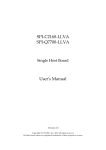
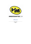
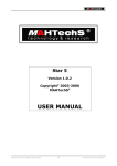
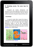
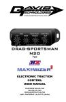
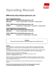
Collision Avoidance System CAS-M
User Manual
1.0 2/2/2015
Table of Contents
Table of Contents
1 System Overview .................................................................................................................................................
1.1 Hardware ............................................................................................................................................................................................
1.2 Wiring ..................................................................................................................................................................................................
1.3 Communication ................................................................................................................................................................................
3
3
4
6
2 Installation Guide ................................................................................................................................................
2.1 Mounting the Radar Display Unit .............................................................................................................................................
2.2 Mounting the Radar Rear Bracket ............................................................................................................................................
2.3 Calibration Concerns ......................................................................................................................................................................
2.4 Wiring the System ...........................................................................................................................................................................
7
7
7
9
9
3 Reading the Display .......................................................................................................................................... 11
3.1 Chevron Markers ........................................................................................................................................................................... 11
3.2 Distance Gauges ............................................................................................................................................................................ 11
3.3 Passing Arrows ............................................................................................................................................................................... 12
4 Vehicle CAN Communication ........................................................................................................................... 13
4.1 Heartbeat Messages .................................................................................................................................................................... 13
4.2 Input Messages .............................................................................................................................................................................. 14
5 Technical Drawings ........................................................................................................................................... 15
2 / 18
Radar Collision Avoidance System
Bosch Motorsport
System Overview | 1
1 System Overview
The Bosch Collision Avoidance System is an augmented-reality rearview display
which uses a Bosch automotive radar sensor and a custom-built Display Unit to
overlay radar data and warnings in real time for improved situational awareness
and safety on track (See Figure 1).
Fig. 1: Example Screenshot from the Radar Display
This interface is designed to be as intuitive as possible, requiring very little driver
training, and allowing the driver to gain more awareness while paying less at‐
tention to the rearview. All of the functions work equally well at night or in bad
weather when visibility is normally lost.
With a momentary glance, the driver can know how many cars are following,
each one’s distance and closing speed, and whether or not they are a faster class.
In addition, bright flashing arrows alert the driver when any car attempts a passing maneuver. Some drivers find that they rarely need to actually look at the
screen, instead just watching for indicators in their peripheral vision.
For a detailed description of the on-screen indicators, see section 3 ‘Reading the
Display’.
1.1 Hardware
The Radar Collision Avoidance System consists of two hardware components, as
shown in Figure 2:
1. Display Unit
2. Long-Range Radar Sensor + Gigabit Ethernet Camera
Bosch Motorsport
Radar Collision Avoidance System
3 / 18
1 | System Overview
Fig. 2: Collision Avoidance System´s Hardware Components
The Radar Display Unit is a custom-built 7” integrated LCD and Linux PC which
combines the data from the Radar Sensor with the video from the Camera in real
time. This is mounted on the vehicle’s dashboard, replacing the traditional rearview display. Connection is made through a single Autosport.
The Long-Range Radar Sensor (LRR3) and Gigabit Ethernet Camera are mounted
together in the tail of the vehicle with a supplied bracket, replacing the traditional rearview camera. The orientation of these sensors is important, so the procedure outlined in 2.2 Mounting the Radar Rear Bracket must be followed. With
the supplied sub-loom, connection to both sensors is made through a single Autosport.
1.2 Wiring
Wiring of the system is fairly straight-forward, although there are certain requirements to meet which are described in 2.4 Wiring the System. At the highest
level, the “Main” Autosport connector on the Display Unit will connect to the following places:
1. The rear bracket sub-loom connector
2. Vehicle power
3. Remote download/debug port (optional)
Aside from the “Main” connector (AS012-35PN), the Display Unit has a “Debug”
connector (ASDD006-09SN) which provides an additional way to access the system for maintenance or downloading.
The LRR3 sensor and GigE camera are broken out from a single Autosport connector (AS010-35PN) via the Rear Radar Sub-Loom. The pinout for this connector, as well as the Display Unit connectors, can be found in enclosed Appendix.
4 / 18
Radar Collision Avoidance System
Bosch Motorsport
Radar Collision Avoidance System
GND (Kl.31)
Optional Power Interface
4
V CAN_H
5
6
V CAN_L
+12V (Kl.15)
+12V (Kl.15)
1
1
F.02U.S00.087-01
13
9
8
7
6
5
4
3
2
Collision Avoidance
System Harness
. .
. .
02 Updated Spec
01 initial drawing
.
.
.
.
.
.
2014.05.05 M. Haas .
2013.10.03 P. Jayaraman
11
10
9
8
7
6
5
11
4
10
3
12
2
Rear Bracket Connector
AS610-35SN
Display Main Connector, V+ and GND max current: 2-3 amps
Rear Bracket Connector, V+ and GND max current: 0.5 amps
Power Connector: Redundant power and ground pins may not be necessary.
All connectors fully populated with appropriate pin / socket.
All dimensions in mm unless otherwise specified.
All not marked wires are AWG22.
Use ethernet cable CAT 6e.
F.02U.V00.xxx-01
-
Note(s):
GND (Kl.31)
3
GigE_1
Orange Stripe
GigE_1
2
GigE_2
Orange
GigE_2
1
GigE_3
Green Stripe
GigE_3
+12V (Kl.15)
+12V (Kl.15)
GigE_4
Blue
GigE_4
Orange Stripe
GigE_5
Blue Stripe
GigE_5
Orange
GigE_6
Green
GigE_6
Green Stripe
GigE_7
Brown Stripe
Blue
GigE_8
Brown
GigE_7
Blue Stripe
V CAN_H
GigE_8
Green
RCAN_H
RCAN_H
Brown Stripe
RCAN_L
RCAN_L
Brown
V CAN_L
Display Main Connector
AS612-35SN
12
13
22
GND (Kl.31)
USB_VCC
14
USB2_DUSB2_D+
USB_GND
USB1_D+
USB1_D-
.
.
BEG/MSD-NA
BEG/MSD-NA
15 16 17 18
20 21
N/C
N/C
F.02U.S00.087-01
Collision Avoidance System Harness
.
.
MSD-NA
MSD-NA
N/C
Bosch Motorsport
GND (Kl.31)
Vehicle Power Connector
AS108-35SN
System Overview | 1
5 / 18
1 | System Overview
Fig. 3: Harness System
1.3 Communication
For full functionality, a vehicle CAN bus connection must be made to the Radar
Display Unit. The Display will report status, error codes, storage space, and temperature, and expects to be supplied the vehicle’s speed, yaw rate, dimmer position, and control bits. These bit positions are all defined in section 4.
If the vehicle CAN bus is not connected or speed data is not available, the Display will function in “standalone mode”. In this mode it will be unable to generate the “Seconds Back” gauge, identify faster-class vehicles, or filter out stationary objects.
Dimmer position is used to reduce the Display’s brightness when racing at night.
It accepts a value from 0 to 5, where ‘0’ is fully dimmed, and ‘5’ is fully bright. The
system can be run without this functionality, but the display is very bright so it is
not recommended if any racing will be done at night.
Yaw rate is used to smooth out and correct the interpolation between radar
readings, resulting in a more accurate markers and predictions. The system will
also function without this data, but performance will be degraded.
Control Bits are used to set custom configurations for the CAS-M. These settings
are turned on by setting a ‘1’ in the bit position defined as follows:
0x1 - Metric - Interpret the input speed signal as km/h
0x2 - FilterOff - Don't throw away stationary objects
0x4 - FlipCamera - Camera is mounted upside down
0x8 - FlipRadar - Radar is mounted upside down
0x10 - Diagnostics - Show diagnostics on screen
6 / 18
Radar Collision Avoidance System
Bosch Motorsport
Installation Guide | 2
2 Installation Guide
2.1 Mounting the Radar Display Unit
There are four M5, 0.8 pitch threaded mounting holes on either side of the Display Unit, spaced 63.5 mm (2.5 inch) apart (See Figure 4). Using these holes, install the Display Unit on or near the dashboard. It should be high enough to be
in but not obstructing the driver’s field of view, with the plane of the LCD square
to the driver’s eyes. For a more detailed specification of the mounting holes location, see the following drawing (Figure 4). Brackets must be designed to constrain the weight of the Display Unit (0.865 kg) in a collision.
Fig. 4: Mounting Holes of the Display Unit
It is also recommended to leave the back of the Display Unit open so that the
Reset Button and Autosport connectors on the rear are accessible.
2.2 Mounting the Radar Rear Bracket
Assuming the supplied rear bracket is being used (as is highly recommended),
the procedure in this section should be followed. In order of importance, the Radar sensor must be longitudinally and laterally level, aligned with the vehicle’s
longitudinal axis, and mounted on the vehicle’s lateral centerline.
2.2.1 Choosing the Mounting Location
The Radar sensor should be mounted on the centerline of the vehicle or as close
as possible. This will ensure that competitors passing on either side are predicted
with equal accuracy. The height of the sensor is not as vital, but 60 cm – 90 cm
feet off the ground will ensure maximum range. If the Radar rear bracket is not
being used, the camera must also be mounted near the centerline, ideally adjacent to the Radar sensor and on the driver’s side.
Bosch Motorsport
Radar Collision Avoidance System
7 / 18
2 | Installation Guide
It is critical that the Radar sensor have an unobstructed (or Radar-transparent)
view out the rear of the vehicle. There must be a 45° cone free of conductive materials extending from the base of the Radar sensor dome (plus a reasonable
margin of safety). The sensor may be mounted with the dome protruding from
the rear fascia, as in Figure 5, or behind a thin layer of vinyl, fiberglass, or Kevlar.
Fig. 5: Radar Sensor and Camera Installed in Corvette Racing C6.R
The recommended mounting location at the top-center of the rear fascia should
satisfy all of these requirements. The rear window may also be used, but there
must be a clear view underneath the wing and the camera’s image must not be
distorted by the window.
The designed orientation of the Radar bracket is with the Radar connector facing
up. If it cannot be packaged in this orientation, it can be rotated by 180° by
changing the control bits in the CAN msg 0x3D1.
2.2.2 Preparing the Mounting Holes and/or Bracket
Once the mounting location is determined, spacers or a bracket will need to be
fabricated to mount the Radar bracket to the rear fascia or chassis, and holes will
need to be cut into the rear fascia (respecting the Radar sensor’s view requirements in 2.2.1 Choosing the Mounting Location). The template in Figure 5
shows locations of the mounting and sensor cutout holes, as viewed from the
rear of the vehicle.
The mounting spacers or bracket should be constructed and installed in such a
way that the Radar bracket is always level laterally, and its longitudinal angle can
be adjusted to level (by shimming for example).
2.2.3 Leveling the Sensors
Once the Radar bracket has been mounted in its chosen location, it must be leveled with a digital level. Ideally, the sensor should measure 0.0° to vertical. Use
shims between the bracket and vehicle to get as close to this as possible, at least
within 0.2°. For the bolt spacing of the bracket, a 0.040” (1 mm) shim will change
its angle by 0.5°. Avoid twisting the bracket by installing the same number of
shims on each side.
8 / 18
Radar Collision Avoidance System
Bosch Motorsport
Installation Guide | 2
First ensure that the car is sitting level (e.g. with laser-leveled scales), and the Radar bracket is installed securely in its mounting location.
If the back of the Radar sensor is accessible, place the digital level against the
back face. Otherwise if the cutout is large enough to allow it, use an alignment
jig such as a 2.25” (5.12 cm) ID tube to align the digital level with the flat face
surrounding the dome on the front of the sensor. If neither of those is possible,
the end of the camera’s lens tube can be used with an alignment jig such as a
1.5” (3.81 cm) OD tube (being careful not to scratch the glass).
It is a good idea to periodically check that the sensor is still level, such as between events. Also, remember to always shim the entire bracket as a unit, and
never alter how the Radar sensor or camera is installed in the bracket (more in
2.3 Calibration Concerns).
2.3 Calibration Concerns
In order to match radar markers to coordinates on the video, the Camera and Radar sensor must be calibrated to each other very precisely. To this end, there is a
generic calibration file stored on the Display Unit, and an adjustment matrix stored on each GigE Camera for the specific bracket and Radar sensor.
A difference of 1° will produce a noticeable offset in the chevron markers, therefore it is very highly recommended to use the provided bracket. The bracket becomes warped from a collision or mishandling.
If either of the sensors need to be serviced, or body repairs need to be performed that require removing the sensors, it is important to remove the bracket
as a unit rather than removing the sensors from it.
2.4 Wiring the System
2.4.1 Display Unit to Rear Bracket
All of the pins in the Radar Rear Bracket Sub-Loom Autosport connector map directly to pins in the Display Unit’s main Autosport connector (the power pins can
be spliced, or pulled from elsewhere on the car), as long as they are both on the
same relay. The pinouts can be found in the 5 Technical Drawing.
The camera uses a Gigabit Ethernet interface, which is uncommon in motorsports
but is fully robust as long as the following requirements are met:
1. The twisted pairs in the pinout MUST be respected. Ideally, each pair should
have a different twist rate to reduce cross-talk. Cat6 or Cat5e networking cable may be used to meet this requirement provided it has the appropriate
temperature ratings and is stranded.
2. Due to the increased electrical noise present in a racecar, the Harness should
be kept as short as possible.
3. There should be as few connectors as possible, as each one is an opportunity
for noise to enter. Any junction boxes must respect the twisted pairs internally.
Bosch Motorsport
Radar Collision Avoidance System
9 / 18
2 | Installation Guide
The Radar sensor communicates via a standard CAN bus, with 120 Ohm terminating resistors pre-installed in the Display PC and rear sub-loom. If the rear subloom is not used, then that end of the bus must be terminated. As with any CAN
bus, these wires must be twisted.
2.4.2 Vehicle Power
Both the Display Unit and the rear bracket should be powered off the vehicle’s
master relay, so that starting and stopping the engine does not cause the system
to lose power. The boot-up process takes 20 to 30 seconds, and excessive power
cycling may reduce the reliability of the system.
The power circuit for the Display Unit will draw 1 Amp and the rear bracket will
draw about 0.5 Amps. Keeping the power sources and ground circuits isolated
from electrically noisy equipment on the car is also recommended.
2.4.3 Vehicle CAN
A single 1 Mbps CAN connection is available through the Display Unit’s main
connector. This should be connected to any available CAN bus capable of logging and sending the appropriate data.
If there is no CAN bus available to the system, it may be left disconnected, but
this is highly discouraged. It will be impossible to diagnose any failures or monitor the status and health of the system, and several features will not work, such
as the “Seconds Back” gauge, faster-class detection, and stationary object rejection.
The communication protocol for the system is described in 4 Vehicle CAN Com‐
munication.
10 / 18
Radar Collision Avoidance System
Bosch Motorsport
Reading the Display | 3
3 Reading the Display
3.1 Chevron Markers
Each car detected by the Radar sensor will be indicated by a 4-meter-wide chevron marker hovering above it. The chevrons also have a diamond-shaped tail
drawn 1 meter from the ground, so the position of close-up competitors can still
be judged.
Fig. 6: Example Screenshot with 3 Chevron Markers, Including One P-Car
The chevrons are designed to convey a wealth of information as quickly as possible, using the following features. Some drivers find that they don’t need to look
at the screen most of the time, instead watching it in their peripheral vision.
1. Size = Distance. Since they are drawn in 3D, each marker’s size on screen indicates its distance.
2. Position = Position. The markers are drawn on screen as if they were actually floating above the cars.
3. Color = Closing speed. A red marker is rapidly closing in, a green marker is
rapidly falling away, and a yellow marker is matching speed. The markers will
follow a smooth gradient between these colors; for example, an orange
marker is closing gradually, and a light green marker is falling away gradually.
4. Cross = P‐Car. When a cross is drawn over the marker, as in the rightmost
car in Figure 6, it means that the competitor is gaining by over 0.1 seconds
per second, and is therefore probably a faster class.
3.2 Distance Gauges
In addition to the size of the chevron markers, the distance to each competitor is
also indicated in real numbers using the two gauges on the left and right side of
the screen (see Figure 6). Each competitor will have a diamond indicator on each
gauge, their respective colors matching their chevron colors.
1. Left: “Meters” Gauge. Indicates the distance to each competitor in meters.
Bosch Motorsport
Radar Collision Avoidance System
11 / 18
3 | Reading the Display
2. Right: “Seconds” Gauge. Integrates the vehicle’s speed history to calculate
the lead over each competitor, displaying that lead in seconds.
As the vehicle speed varies through corners and straights, the “Meters” gauge
will show the competitors becoming closer and farther away, while the seconds
gauge will remain fairly constant, reflecting only changes in actual lead.
Notice
If the Display Unit hat not been installed with a connection to
the vehicle´s CAN bus, or is not sent the vehicles speed over
that bus, the “Seconds” gauge will not be displayed.
Consequences
3.3 Passing Arrows
Fig. 7: Example Screenshot with Passing Arrow
The system also attempts to predict and detect when competitors move to execute a pass. When this happens, a bright flashing arrow is displayed on the
screen for 2 seconds, indicating which side the competitor is likely passing on
(see Figure 7).
The color of the flashing arrow will indicate the last measured closing speed of
the competitor. Thus a bright red arrow indicates a competitor “flying by,” while
a yellow or green arrow indicates a more hesitant pass, which might result in an
aborted attempt.
It is important to remember that the arrows are not infallible. Since there are no
side-looking sensors, each arrow represents only a prediction. Through system
testing the algorithm has been tuned to err on the side of caution, not displaying
either arrow if the passing side could not be determined with high confidence.
About 90% of passes are indicated with the arrows, so the driver must still be
alert to secondary indications, such as competitors disappearing from the rearview, or approaching a common passing area.
12 / 18
Radar Collision Avoidance System
Bosch Motorsport
Vehicle CAN Communication | 4
4 Vehicle CAN Communication
The Display Unit reports heartbeat messages and reads vehicle inputs over a 1
Mbps CAN bus through the main Autosport connector.
4.1 Heartbeat Messages
The Display Unit reports two periodic heartbeat messages, one for hardware and
OS status, and another for software status. Full message specifications can be
found in the provided DBC file as well as this section.
The Hardware Heartbeat message has ID 0x3D2, is sent at 5 Hz (200msec),
and contains the following signals:
Bit 7
Bit 6
Bit 5
Byte 0
Bit 4
Bit 3
Bit 2
Bit 1
Bit 0
Timestamp
Byte 1
Byte 2
Byte 3
Byte 4
HW Status Bits
Byte 5
SSD Space
Byte 6
CPU Temp
Byte 7
SSD Temp
Signal
Units
LSB
Description
Timestamp
S
1
Linux epoch time (seconds since Jan 1st
1970). Unsigned big-endian (Motorola)
HW Status Bits
Flags
0x01: Watchdog – Radar log not being
written
0x02: Watchdog – Video log not being
written
0x04: Warning – CPU over temp
0x08: Warning – Low HDD space
0x10: Internal Warning – Watchdog
measurement failed
0x20: Not Logging
SSD Space
GB
1
Hard drive space available for logging
CPU Temp
°C
1
CPU temperature
SSD Temp
°C
1
SSD temperature
The Software Heartbeat message has ID 0x3D3, is sent at 30 Hz (33.3msec),
and contains the following signals:
Bit 7
Bit 6
Bit 5
Bit 4
Bit 3
Byte 0
SW Status Bits
Byte 1
Cars Detected
Bit 2
Bit 1
Bit 0
Byte 2
Bosch Motorsport
Radar Collision Avoidance System
13 / 18
4 | Vehicle CAN Communication
Byte 3
Byte 4
Byte 5
Byte 6
Byte 7
Signal
Units
SW Status Bits
Flags
LSB
Description
0x01: Logging
0x02: Warning – Radar Failure
0x04: Warning – Video Failure
0x08: Warning – Vehicle CAN Failure
0x10: Pass detected on Left
0x20: Pass detected on Right
Cars Detected
Cars
1
Number of cars currently on screen
(max = 32)
4.2 Input Messages
The Vehicle Inputs message should have ID 0x3D1, be sent to the Display Unit
at 25 Hz (40msec), and contain the following signals:
Bit 7
Bit 6
Bit 5
Bit 4
Byte 0
Bit 3
Bit 2
Bit 1
Bit 0
Speed
Byte 1
Byte 2
Yaw Rate
Byte 3
Byte 4
Dimmer Pos
Byte 5
Control_Bits
Signal
Units
LSB
Description
Speed
MPH
0.1
Vehicle current speed (from wheel sensor). Unsigned big-endian (Motorola).
Yaw Rate
Deg/s
0.001
Vehicle current yaw rate (from gyroscope). Signed big-endian (Motorola).
Dimmer Pos
0–5
Dimmer switch position
0 = fully dim
5 = fully bright
Control_Bits
None
Bit is set, enables the following below
0x 1 - Metric - Interpret speed as km/h
0x 2 - FilterOff - Don't throw away stationary objects
0x 4 - FlipCamera - Camera is upside down
0x 8 - FlipRadar - Radar is upside down
0x10 - Diagnostics - Show diagnostics on screen
14 / 18
Radar Collision Avoidance System
Bosch Motorsport
Technical Drawings | 5
5 Technical Drawings
Fig. 8: Camera Unit
Fig. 9: Display Unit
Bosch Motorsport
Radar Collision Avoidance System
15 / 18
Bosch Engineering North America
Motorsports
38000 Hills Tech Drive
Farmington Hills, MI 48331-3417
United States of America
www.bosch-motorsport.com