1
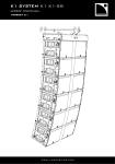
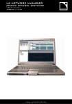
User Manual
ProSight SLST • ProSight SMMT • ProSight SCT30
The SSE ProSight Inclinometer System is a precise tool for
use in the installation of line array loudspeaker systems.
The ProSight Inclinometer System comprises the following components:
ProSight SLST
ProSight SMMT
The Sender Unit mounts to the system
bumper or rigging frame. The SLST laser
module (as shown in the above photograph)
contains a precision solid state inclinometer,
in a rugged housing case. Mounting brackets
are available separately for a number of key
line array systems.
The Meter Unit containing a backlit display
has a two-button menu driven interface.
The Meter Unit operates on 6 x AA batteries.
Prosight cable SCT30
A 30m long 6-pin XLR-XLR cable that
connects the Meter Unit to the Sender Unit.
Principal features of the ProSight
Inclinometer system:
Precision angle measurement to +/- 0.05 deg.
resolved to +/- 0.1 deg. displayed.
Intelligent interpolative measurement - the final
resting angle of the system is displayed within
three periods of oscillation whilst the system is moving
after motor hoist adjustment, giving an accurate angle
reading. This feature reduces installation time, as the user
does not need to wait until the PA system comes to rest after
each angle adjustment.
Many Sender Units may be used with one Meter Unit. Calibration information is
stored in the Sender Unit using non-volatile memory and remains accurate after
the Meter Unit is disconnected. The Sender Unit may be re-calibrated on the fly
to any angle within its range from menu controls on the meter unit, allowing
adjustment of PA system elevation to be made in absolute values if required.
The Sender Unit has an on-board green laser that is calibrated parallel to the
Sender Unit mounting faces and switched from menu commands on the Meter
Unit. Green lasers are 20 times more visible than red lasers and provide highly
visible indication of the aiming of the PA system.
SSE Audio Group
Burnt Meadow House, North Moons Moat, Redditch B98 9PA UK
Tel: +44 (0)1527 528822
www.sseaudiogroup.com
The SSE ProSight Inclinometer System
Serial data connection between the meter unit and the sender unit. Using SSE Prosight
cable we can custom build varying lengths if required (up to 100m), as cable resistance has
no influence upon the calibration of the sender unit. SSE Prosight cable must be used for
correct function of laser.
Rugged packaging for reliable performance and long service life.
• Integration with the Nexo GeoT, GeoD and d&b J series rigging systems – these systems
all have custom mounting points for SSE Prosight providing a reliable and tour friendly
precision tool. A standard fitment bracket is available for use with all 3 of these systems.
• Mounting brackets are available for use with L'Acoustics VDOSC and JBL Vertec. We also
aim to have brackets available soon for L'Acoustics KUDO, Meyer Sound Milo and Adamson
Y18. Please note that SSE accepts no responsibility for using Prosight systems for other
uses than those recommended with official brackets.
• SSE innovation and reliability.
• Fully functional with any make of loudspeaker system using custom mounting hardware.
Using the ProSight Inclinometer System
The Operation Menu
The ProSight is operated from the meter unit by means of two buttons, one RED and the
other GREEN. In most screens the RED button calls the menu item and the GREEN button
executes the command. The diagram below illustrates the menus and button actions.
ProSight Menus and Functions
SSE
Switch on - press both buttons simultaneously
FIVE SECONDS
+0.00˚
LASER
L-ON
Laser on/off
POWER
Power off
LIGHT
LIGHT
Backlight level 1/2 off
ZERO
SURE?
Re-calibrate - press both buttons simultaneously
Z-SET
Re-calibration confirm
FIVE SECONDS
+0.00˚
V 1.4
Returns to angle display
Software version
Indicates a
button press
Indicates a
button press to
submenu/execute
command
Red button
moves to next
menu item
Green button
makes a
selection.
Auto angle display revert
from any menu = 5 seconds
Auto Power Off from last
button press = 3 minutes
Both buttons pressed simultaneously when switching on unit, and when confirming you are sure to a zero set.
P r o d u c t
G u i d e
S e c t i o n
O n e
Page 2
The SSE ProSight Inclinometer System
Connect the inclinometer cable to the sender unit and to the meter unit.
NOTE: The Inclinometer Cable is durable but requires the same handling precautions and strain relief that users
would provide for any other flown cable.
BEFORE SWITCHING ON: Ensure that the laser safety precautions have been followed – see page 7.
Switch on the unit by pressing the RED and the GREEN buttons simultaneously. The unit checks the backlight
and displays ‘SSE’ for approximately 5 seconds during the boot sequence. After booting the unit displays the
current angle readout in degrees.
NOTE: The initial angle reading is relative to the last calibration of the unit.
In order to be sure that the inclinometer measurement is correctly calibrated to the bumper/cabinet the
following procedure must be followed:
Sender Unit angle calibration procedure:
• Place the bumper/cabinet on a solid, stable surface.
• Take a good quality spirit level or calibrated digital level and place it on the top edge of the bumper/cabinet.
• Pack the bumper/cabinet at the front or rear as required so that the bumper/cabinet is perfectly horizontal.
• Switch on the ProSight and scroll to the ‘ZERO’ menu item using the RED button. Press the GREEN button and
note that the display reads ‘SURE?’ Immediately press and HOLD the RED button and then press the GREEN
button. The display reads ‘Z-SET’ for approximately 5 seconds whilst the calibration register is reset and the
Sender Unit re-boots.
• The Sender Unit is now calibrated to read +0.00° when the bumper/cabinet is perfectly horizontal.
NOTE: It is normal for the Meter Unit display to occasionally display +/- 0.01° when static. This is because the
ProSight continually calculates the static angle from dynamic information and is in fact fractionally more
accurate when the PA system is swinging than it is when absolutely still.
Angle display and interpolation
The ProSight system is now ready for use and will display the computed static resting angle of the Sender Unit
when the Meter Unit is active. The accuracy of the reading is a function of the number of periods of pendulum
‘swing’ that the PA system has undergone. As a guideline, the angle display has the following accuracy:
1 periods (cycles) of swing: +/- 1.0°
2 periods (cycles) of swing: +/- 0.5°
3 periods (cycles) of swing: +/- 0.1°
It will be obvious that the measurement cannot be relied upon when the PA system hoists are actually being
operated. Once the hoist(s) have stopped the Meter Unit display quickly resolves the measurement. A
satisfactory value for the resting angle is normally displayed within a few seconds.
P r o d u c t
G u i d e
S e c t i o n
O n e
Page 3
The SSE ProSight Inclinometer System
Operating the laser
Laser Safety
Lasers are potentially extremely dangerous. Please observe all safety
precautions when using this equipment. Never use the laser when hand holding
it, and never let anyone into the target area of the laser whilst it is in use. For a
full listing of precautions please see page 7.
The laser may be operated by scrolling to the LASER menu using the RED button and switching ON and OFF
using the GREEN button.
NOTE: Observe safety precautions before using the laser – see above.
The laser is used to confirm that the upper margin of the PA systems dispersion is reaching the design target.
Line array design software illustrates specifically where the top cabinet should be pointing in relation to the
venue, therefore when the array is positioned to the correct elevation and the correct angle, the laser equally
should be targetted at this spot.
Once the array installation is complete the Meter Unit should be disconnected from the Inclinometer Cable and
can be used with other Sender Units. If subsequent adjustment of the array is required the Meter Unit may be
re-connected to the Sender Unit without loss of calibration.
Adjusting the angle of the PA system using relative values
Once in position, the Sender Unit can if required be re-calibrated in place to relative zero by following the
calibration procedure given above. This allows the PA system to be re-adjusted relative to its original elevation
by reading the value of the adjustment rather than the absolute value.
In this case the user must be careful to note when the Sender Unit has been re-calibrated because its horizontal
position will no longer be 0.00°. For this reason it is wise to calibrate each Sender installation before use unless
you are confident that it has not been re-calibrated to some other angle.
This function may be useful when re-adjusting a system that has been installed to a known position but where
the calibration state of the Sender Unit is unknown or appears to be incorrect.
Limits of angle measurement
The ProSight has a usable range of +/- 30° with full accuracy. The sensor is capable of measuring angles up to
44° but with reduced accuracy of +/- 1° at 40°. The additional range is left available to the user but should be
used with caution. If extreme angles are needed outside the +/- 30° range it is preferable to mount the Sender
Unit at a known angle that is closer to the target angle however this would require customised mounting
hardware.
Horizontal (azimuth) reference
With correct calibration (see SLST Laser Sender Calibration) the laser provides an accurate azimuth reference as
well as vertical.
P r o d u c t
G u i d e
S e c t i o n
O n e
Page 4
The SSE ProSight Inclinometer System
Power management
Automatic power off
The ProSight Inclinometer system manages its power consumption and auto powers off 3 minutes after the last
button push.
Battery condition and replacement
The Meter Unit requires 6 x AA batteries for operation (not included in the shipping package). Only high
performance alkaline type batteries such as Duracell MN1500 LR6 should be used.
Low battery indication: When the batteries are low the display shows ****** and the functions of the ProSight
are disabled.
To replace the batteries
• Remove the 2 x M4 countersunk machine screws in each of the side faces of the Meter Unit.
• Withdraw the inner assembly of the Meter Unit from the outer cover and place on a flat surface.
• Identify the battery bay and disconnect the PP3 type connector.
• Withdraw the battery pack from the battery bay.
• Replace the batteries being careful to observe polarity.
• Replace the battery pack and re-connect
• Replace the outer cover and re-fit the screws. Do not over tighten.
Battery Life
The SLST laser module is by far the most demanding feature of the system in terms of power consumption,
followed by the backlight function and finally the inclinometer electronics. Users should expect approximately
2.5 hours continuous use of the laser.
Servicing
The SLST laser module and the SLST Meter Unit contain no user serviceable parts. Please refer to your local SSE
distributor for service.
Calibrating the SLST laser module
Careful calibration of the laser is required as small errors multiply to produce large errors over distance. Use the
following procedure to calibrate the laser.
The Sender Unit must be placed in a position where it is registered vertically and horizontally – e.g. on a solid
table with a block clamped to it as a side fence. The laser output beam should be aimed at a vertical surface at
least 20m distant from the Sender Unit.
Switch on the laser and note where the laser dot falls on the vertical target surface. Make a mark on the surface
at the centre of the laser dot.
Rotate the Sender Unit 180° around the axis of the laser output beam. Ensure that the Sender Unit is firmly
registered against the fence and observe the new position of the laser dot. Make a second mark at the centre of
the dot and make sure that the two marks are identified for vertical orientation.
P r o d u c t
G u i d e
S e c t i o n
O n e
Page 5
The SSE ProSight Inclinometer System
Turn the Sender Unit through 90° and repeat the process,
identifying the two laser dots marks for horizontal orientation.
After following this procedure the target surface should have
four marks as shown in the diagram at left.
V1
H2
H1
Connect the marks V1 and V2 with a line and similarly the pair
of marks H1 and H2. The point where the two lines coincide is
the desired calibrated target point for the laser dot. Make a
clear mark on the target surface at this point. Calibrated target
for the laser dot
V2
The target surface should
have four marks as shown.
V1
With the Sender Unit firmly registered against the
fence adjust the four M3 machine screws around
the circumference of the laser bezel until the laser
dot falls on the desired calibration mark. The
adjustment is quite sensitive and more so the
further the target surface is from the Sender Unit.
Make only small adjustments to each of the screws
and make sure that the screws are not tightened
completely.
H2
H1
Calibrated target
for the laser dot
V2
Adjust the four M3 machine screws around the
circumference of the laser bezel until the laser
dot falls on the desired calibration mark.
When the calibration is
completed place a drop of
thread lock on each of the
screw heads.
When the calibration is completed place a drop of
thread lock on each of the screw heads and label the
sender unit as having been calibrated with the date and
name of the person doing the work.
SSE ProSight is an integrated part of your rigging system and should be
regarded with the same respect as any other rigging component. It has the
added issue of the high brightness laser that requires additional safety
considerations. Please give careful attention to the following safety
warnings panel on the following page before using your ProSight
Inclinometer System.
P r o d u c t
G u i d e
S e c t i o n
O n e
Page 6
The SSE ProSight Inclinometer System
MOST IMPORTANT –
Safety precautions when using laser equipment.
• CAUTION – Use of controls or adjustments or performance of procedures other than those specified
herein may result in hazardous radiation exposure.
• NEVER look directly into the laser, even when it is switched off, as someone may activate it without
warning you.
• WARN others in the venue that you are going to use a laser and move them away from the target
area before activating the ProSight. Ensure that others do not enter the target area of the laser
whilst it is in use and ensure that the meter unit is to hand at all times so that the beam can be
switched off immediately if necessary.
• Use the laser for the minimum amount of time and switch off as soon as the measurement is
complete. Disconnect the cable from the Meter Unit as soon as possible and ALWAYS ensure that
the Meter Unit is disconnected when the public have access to the venue.
• NEVER use the laser in any other application than it is designed. DO NOT operate the laser when
hand holding the Meter Unit. There are serious penalties for using a laser in any manner that may
cause accident or injury. Particularly it is very dangerous to point the laser at vehicles or aircraft.
• Carry out alignment procedures and other adjustments and alterations, which may give rise to
unexpected beam paths or reflections, with the laser switched off. Avoid leaving the laser turned on
whilst unattended.
• IMPORTANT – Your ProSight system
is shipped with the following labels,
please DO NOT remove under any
circumstances. They are affixed as
shown on the SLST unit.
Wavelength
Peak / CW Power
Pulse Energy
Pulse length
IE
C / EN 60B25-1 (2001)
LASER
APERTURE
Wavelength
Peak / CW Power
Pulse Energy
Pulse length
IEC / EN 60B25-1 (2001)
LASER
APERTURE
This label should be affixed
next to the Aperture at the
end of the unit.
LASER RADIATION
AVOID DIRECT
EYE EXPOSURE
CLASS 3R LASER PRODUCT
This label should be affixed
next to the XLR connector at
the end of the unit.
Wavelength
Peak / CW Power
Pulse Energy
Pulse length
IE
C / EN 60B25-1 (2001)
This label should be affixed
next to the XLR connector at
the end of the unit.
LASER RADIATION
AVOID DIRECT
EYE EXPOSURE
CLASS 3R LASER PRODUCT
This label should be affixed next
to the laser aperture at the end
of the unit.
LASER
APERTURE
Laser Specification
LASER RADIATION
AVOID DIRECT
EYE EXPOSURE
CLASS 3R LASER PRODUCT
Wavelength 532nm
Max power <5mW
Class 3R laser product to IEC/EN 60825-1 (2001)
P r o d u c t
G u i d e
S e c t i o n
O n e
Page 7
The SSE ProSight Inclinometer System
Please also ensure that the following label remains affixed to the SLST unit
SLST SENDER UNIT
Serial No:
Burnt Meadow House North Moon Moat Redditch B98 9PA UK
Complies with 21 CFR 1040 with deviations pursuant to Laser Notice 50, and with IEC/EN 60825-1 (2001)
Other important safety issues:
• The Sender Unit must be safely attached to the loudspeaker array structure when used above
2m from ground level. DO NOT fix the Sender Unit with tape or Velcro. Always ensure that a
suitable mounting fixture is used.
• The use of ProSight does not preclude the obligation to follow normal rigging safety
procedures.
• Be aware that any object left on the top of a PA system during installation may fall when the system is
operated. Always check that all accessories are secured before final hoisting.
• When making adjustments to the PA system with motor hoists watch the hoist – not the Meter Unit! Check the
measurement only when you are satisfied that the hoist has finished moving safely.
• When using the Meter Unit be aware of other rigging operations around you. Always follow the appropriate
safety procedures for the site (including wearing the appropriate protective clothing and headgear).
• Always store the meter unit and the cable properly after use to prevent trip hazards or damage.
• Prosight components are not waterproof but are shower resistant. All brackets offer suitable protection from
precipitation. When mounted into a Nexo GeoT bumper, the frame will act as an umbrella and offer weather
protection to SLST Module. Always take care when using ProSight outdoors.
• As with any component of flown loudspeaker arrays, regular safety inspections are obligatory.
P r o d u c t
G u i d e
S e c t i o n
O n e
Page 8