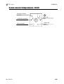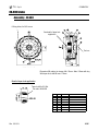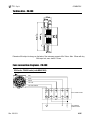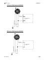
1
.E N G . COMBIFLEX Pneumatic brake USER’S MANUAL Re S.p.A. COMBIFLEX Contents Warnings............................................................................................................................1 Description ........................................................................................................................1 Mounting the Combiflex brake on your machine...........................................................2 Replacing the pads ...........................................................................................................3 Replacing the turbin disc .................................................................................................4 CX.200 brake......................................................................................................................5 Assembly - CX.200........................................................................................................................... 5 Turbine disc - CX.200 ...................................................................................................................... 5 CX.250 brake......................................................................................................................6 Assembly - CX.250........................................................................................................................... 6 Turbine disc - CX.250 ...................................................................................................................... 7 Cover - CX.250.................................................................................................................................. 7 6 poles female tap linkage diagram - CX.250................................................................................. 8 CX.251 brake......................................................................................................................9 Assembly - CX.251........................................................................................................................... 9 Turbine disc - CX.251 .....................................................................................................................10 Cover - CX.251.................................................................................................................................10 Electro pneumatic box - CX.251 ....................................................................................................11 6 poles connector linkage diagram - CX.251................................................................................11 CX.300 brake....................................................................................................................12 Assembly - CX.300..........................................................................................................................12 Turbine disc - CX.300 .....................................................................................................................13 Electro pneumatic box - CX.300 ....................................................................................................13 6 poles connector linkage diagram - CX.300................................................................................14 CX.400 brake....................................................................................................................15 Assembly - CX.400..........................................................................................................................15 Turbine disc - CX.400 .....................................................................................................................16 Fans connection diagrams - CX.400 .............................................................................................16 CX.500 brake....................................................................................................................18 Assembly - CX.500..........................................................................................................................18 Turbine disc - CX.500 .....................................................................................................................19 Fans connection diagrams - CX.500 .............................................................................................19 Fans for CX brakes - technical data ..............................................................................21 CX half caliper - internal side.........................................................................................22 CX half caliper - external side........................................................................................22 Reduced calipers ............................................................................................................23 Pads..................................................................................................................................24 Guarantee ........................................................................................................................25 I Re S.p.A. COMBIFLEX Warnings The present manual is for device fitters and operators. It provides indications on the intended use of the device, technical specifications and instructions for installation, adjustment and use. This manual is an integral part of the device and must be kept until the device is decommissioned. It reflects the technical state of the device at the time of its sale. The plant builder may include the present manual in the documentation for plant use. Re S.p.A. reserves the right to update its production and/or manuals without updating products already sold and previous manuals. Since the device forms part of a plant, the plant builder is responsible for ensuring that all parts comply with the laws in force in the country in which it is installed. The device must be fitted and adjusted by qualified technical personnel. It may be moved manually. Description The COMBIFLEX brake has been designed to be a compact, inexpensive and high performance brake. This ensures that it will completely satisfy the requested application demands. This brake’s simple, low maintenance design gives it the advantage of being easily disassembled for periodical maintenance. To maintain the brake always in optimal functioning conditions it is recommended: verify the correct application of the brake control the pads wear and replace them when necessary (see page 3 Replacing the pads) control the turbine disc and replace it when necessary (see page 4 Replacing the turbine disc) verify that the disc surfaces are sufficiently smooth, if not turn both of the disc faces being careful to maintain the thickness suitable to use (see page 4 Replacing the turbine disc) Supply the calipers using compressed “dry” air, without any kind of lubricating The air pressure used to supply the calipers, must not be more than 6bar. If a higher air pressure is necessary for particular applications, special calipers are available (on customers requests): these are interchangeable to the standard calipers, and allow to supply the brake until 10bar. Rev. 23/12/11 1/25 Re S.p.A. COMBIFLEX Mounting the Combiflex brake on your machine A B C D E Mount the brake disc on the shaft without locking it. Assemble the half-housing, attaching it to the machine flange at 4 points labelled “A” in the diagram. Tighten the 4 screws with torque of 2,2 DaNm. Center the disc between the two lining pads using a feeler, then lock the disc. Rotate manually the disc and verify that the deviation of the disc’s parallelism in respect of the flange is ± 0,1 mm. Assemble the second half housing as described above in point “B”. Attach the fan (if present) using the 4 screws which are mounted on the fan. Attention! When you mount the fan, verify that the arrow on it is pointing toward the brake (the flow of the air is going from outside into the brake) If the fan is provided with the cover, attach the cover to the brake, using the appropriate fixing screws Rev. 23/12/11 2/25 Re S.p.A. COMBIFLEX Replacing the pads The R15 brake pads (code 01A67016) are produced with material without asbestos and when used correctly will last between 7500 and 10000 hours. However the pad’s lifetime can undergo remarkable variations due to the high exercise temperatures, and it is useful to verify the correct application of the brake. Moreover, we recommend that you inspect the thickness of the pads: the brake pads should be replaced if the thickness reaches 5mm. Attention! Sometimes the pad could wear not uniformly; in this case measure the higher thickness: replace the pad when the higher thickness reaches 6,5mm. Pad to be replaced: Thickness = 5mm (or = 6,5mm in case of not uniformly wear) New pad: Thickness = 10mm Replacing procedure: A B Remove the fan, if present, or the cover (if the fan is provided with the cover). C Remove the first half housing, and then the second half. D Re-assemble both of the half-housings, then attach the fan or the cover, if present, following the procedure on page 2 (Mounting the Combiflex brake on your machine). Dismount the pads fixed to the piston with a retaining spring (code 4258910) using a screwdriver. Replace it inserting new pads and press them until they are seated. Rev. 23/12/11 3/25 Re S.p.A. COMBIFLEX Replacing the turbin disc The cast iron turbine disc does not require particular maintenance procedures. Anyway, we recommend that you inspect the thickness of the disc (this operation is easy to do during the pads replacing, when the brake is dismounted): the disc should be replaced if the thickness reaches 46mm (in CX200, CX250, CX251 and CX300 brakes) or 51mm (in CX400 and CX500 brakes). If the disc surfaces are not sufficiently smooth, turn both of the disc faces being careful the thickness does not reach the minimum values indicated above. New disc: Thickness = 50mm Disc to be replaced: Thickness = 46mm Thickness = 55mm Thickness = 51mm (CX200, CX250, CX251, CX300) (CX200, CX250, CX251, CX300) (CX400-CX500) (CX400-CX500) Replacing procedure: A B Remove the fan, if present, or the cover (if the fan is provided with the cover). C Remove the first half housing, and then the second half. D Mount the new disc, both of the half-housings, then attach the fan or the cover, if present, following the procedure on page 2 (Mounting the Combiflex brake on your machine). Dismount the brake disc from the shaft. Rev. 23/12/11 4/25 Re S.p.A. COMBIFLEX CX.200 brake Assembly - CX.200 6 fixing holes, for M8 screw Mounting flange POS. 1 2 3 4 5 5 5 6 7 8 9 Q.TY 2 X 8 1 1 1 1 8 4 X 1 CODE 4200213 4253100 10001094 01A09003 80000005 80000008 80000014 20000416 4259110 4253200 4204715 DESCRIPTION CX200 HALF HOUSING OUTSIDE CALIPER SCREW 8x100 UNI 5931 CX200 HALF HOUSING PROTECTION GRID CX200 FAN 3606 115V 50/60HZ CX200 FAN 3650 220V 50/60HZ CX200 FAN 24Vdc COD.3314 O-RING 6BIS VITON CX200/300 AIR TUBE INSIDE CALIPER BRAKE FLAT DISC Turbine disc - CX.200 Rev. 23/12/11 5/25 Re S.p.A. COMBIFLEX CX.250 brake Assembly - CX.250 8 fixing holes, for M8 screw Dimension ØA subject to change: Min. 35mm - Max. 70mm with key With taper lock, max shaft Ø 45mm Dimension B: 10mm with long hub - 35mm with short hub Dimension C: 65mm with long hub - 40mm with short hub POS. Q.TY 1 1 1 1 1 1 2 1 3 X 4 X 5 2 6 12 7 6 8 1 9 X 10 X Rev. 23/12/11 CODE 80000024 80000002 80000001 42501001 4253310 4253911 4250212 20000416 4259110 4254718 4253200 4253100 DESCRIPTION FAN DIAM.150 24Vdc FAN SET 7000-V115.50/60HZ FAN SET 7000-V220.50/60HZ CX 250/300 FAN GRILLE INSIDE CARTER OUTSIDE CARTER HALF HOUSING O-RING 6BIS VITON CX 200/300 AIR TUBE MACHINED BRAKE DISC STD INSIDE CALIPER OUTSIDE CALIPER 6/25 Re S.p.A. COMBIFLEX Turbine disc - CX.250 Disc with short hub Disc with long hub (optional) Dimension ØA subject to change on the basis of the customers requests: Min. 35mm - Max. 70mm with key With taper lock, max shaft Ø 45mm Cover - CX.250 CODE 01A09016 01A09026 01A09027 Rev. 23/12/11 DESCRIPTION CX251 COVER 24V 6 POLES CONNECTOR CX251 COVER 115V 6 POLES CONNECTOR CX251 COVER 220V 6 POLES CONNECTOR 7/25 Re S.p.A. COMBIFLEX 6 poles female tap linkage diagram - CX.250 0Vdc fan +24Vdc fan 230/115V 230/115V Rev. 23/12/11 8/25 Re S.p.A. COMBIFLEX CX.251 brake Assembly - CX.251 8 fixing holes, for M8 screw Dimension ØA subject to change: Min. 35mm - Max. 70mm with key With taper lock, max. shaft Ø 45mm Dimension B: 10mm with long hub - 35mm with short hub Dimension C: 65mm with long hub - 40mm with short hub POS. Q.TY CODE DESCRIPTION 1 1 01A09009 COVER 24V 2 1 4254716 BRAKE DISC 3 X 4253200 INSIDE CALIPER 4 X 4253100 OUTSIDE CALIPER 5 1 01A44020 ELECTRO PNEUMATIC BOX 6 2 4250212 HALF HOUSING 7 X 4253911 OUTSIDE CARTER 7 X 4253310 INSIDE CARTER 8 6 4259110 CX250 AIR TUBE 9 12 20000416 O-RING 6BIS VITON - The drawing shows a 3 calipers brake Rev. 23/12/11 9/25 Re S.p.A. COMBIFLEX Turbine disc - CX.251 Disc with short hub Disc with long hub (optional) Hole to mount the pin for proximity reading Dimension ØA subject to change on the basis of customers requests: Min. 35mm - Max. 70mm with key With taper lock, max shaft Ø 45mm Cover - CX.251 CODE 01A09009 Rev. 23/12/11 DESCRIPTION CX251 COVER 24V INSIDE CONNECTOR 10/25 Re S.p.A. COMBIFLEX Electro pneumatic box - CX.251 Note: the electro-pneumatic box is provided with 2 air courses; they are distinguished by different colours of inputs and outputs; implement the pneumatic connections by using input and output of the same colour. N.2 pneumatic inputs N.2 pneumatic outputs 6 poles connector (C053) 6 poles connector linkage diagram - CX.251 Proximity contact YELLOW 0Vdc fan +10/35Vdc proximity GREY BROWN 0Vdc proximity GREEN Rev. 23/12/11 +24Vdc fan WHITE 500mA 12V 11/25 Re S.p.A. COMBIFLEX CX.300 brake Assembly - CX.300 6 fixing holes, for M10 screw Dimension ØA subject to change: Min. 35mm - Max. 85mm with key With taper lock, max. shaft Ø 65mm POS. 1 2 3 Q.TY 2 X 16 CODE 4300210 4253100 10001094 4 1 80000002 4 1 80000001 4 5 6 7 8 9 10 1 1 16 8 X 1 2 43079003 42501001 20000416 4259110 4253200 4304712 10001025 Rev. 23/12/11 DESCRIPTION CX300 HALF HOUSING OUTSIDE CALIPER SCREW 8x100 UNI 5931 FAN SET 7000 V115.50/60HZ FAN SET 7000 V220.50/60HZ CX300 FAN V24 CX250/300 FAN GRILLE O-RING 6BIS VITON CX200/300 AIR TUBE INSIDE CALIPER MACHINED BRAKE DISC SCREW 4x35 UNI 5931 12/25 Re S.p.A. COMBIFLEX Turbine disc - CX.300 Dimension ØA subject to change on the basis of the customers requests: Min. 35mm - Max. 85mm with key With taper lock, max. shaft Ø 65mm Electro pneumatic box - CX.300 Note: the electro-pneumatic box is provided with 2 air courses; they are distinguished by different colours of inputs and outputs; implement the pneumatic connections by using input and output of the same colour. 6 poles connector (C053) N.2 pneumatic inputs N.2 pneumatic outputs B152 connector Rev. 23/12/11 13/25 Re S.p.A. COMBIFLEX 6 poles connector linkage diagram - CX.300 Proximity contact YELLOW 0Vdc fan +10/35Vdc proximity GREY BROWN 0Vdc proximity GREEN Rev. 23/12/11 +24Vdc fan WHITE 500mA 12V 14/25 Re S.p.A. COMBIFLEX CX.400 brake Assembly - CX.400 8 fixing holes, for M10 screw See detail of taper lock application Fan box View from A Dimension ØA subject to change: Min. 35mm - Max. 150mm with key With taper lock, shaft Ø max. 110mm Detail of taper lock application Taper lock 80x120 Std. Re code: 46000080 POS. Q.TY 1 2 2 12 3 24 4 X 5 X 6 24 7 1 8 1 Rev. 23/12/11 CODE 4400210 44091001 20000416 4253100 4253200 10001035 4404712 80000004 DESCRIPTION CX400 HALF HOUSING CX400/500 AIR TUBE O-RING 6BIS VITON OUTSIDE CALIPER INSIDE CALIPER SREW 8x110 UNI5931 BRAKE DISC CX400 FAN 220V 15/25 Re S.p.A. COMBIFLEX Turbine disc - CX.400 Dimension ØA subject to change on the basis of the customers requests: Min. 35mm - Max. 150mm with key With taper lock, max, shaft Ø 110mm Fans connection diagrams - CX.400 24V fan for CX.400 brake (code M0401004) RED BLUE WHITE YELLOW YELLOW-GREEN 1 2 - + FAN CONNECTIONS +24 Vdc P.E. 0 Vdc FAN CUSTOMER'S CONNECTIONS N.C. Rev. 23/12/11 16/25 Re S.p.A. COMBIFLEX 115V fan for CX.400 brake (code 80000003) BROWN WHITE GREEN-YELLOW CAPACITOR 8 µF BLUE BLACK WHITE 115Vac 220V fan for CX.400 brake (code 80000004) BROWN WHITE BLACK WHITE BLUE GREEN-YELLOW CAPACITOR 1,5 µF 220Vac Rev. 23/12/11 17/25 Re S.p.A. COMBIFLEX CX.500 brake Assembly - CX.500 8 fixing holes, for M10 screw Dimension ØA subject to change: Min. 35mm - Max. 160mm with key With taper lock, max. shaft Ø 120mm POS. 1 2 3 4 4 5 6 7 8 9 Rev. 23/12/11 Q.TY 2 X 16 1 1 1 28 14 X 1 CODE 4500210 4253100 10001094 80000010 80000011 4503410 20000416 44091001 4253200 4504717 DESCRIPTION CX500 HALF HOUSING OUTSIDE CALIPER SCREW 8x100 UNI 5931 FAN DIM 250 V115.60 FAN DIM 250 V220.50 CX500 FAN DISC O-RING 6BIS VITON CX400/500 AIR TUBE INSIDE CALIPER MACHINED BRAKE DISC 18/25 Re S.p.A. COMBIFLEX Turbine disc - CX.500 Dimension ØA subject to change on the basis of the customers requests: Min. 35mm - Max. 160mm with key With taper lock, max. shaft Ø 120mm Fans connection diagrams - CX.500 24V fan for CX.500 brake (code M0401004) RED BLUE WHITE YELLOW YELLOW-GREEN 1 2 - + FAN CONNECTIONS +24 Vdc P.E. 0 Vdc FAN CUSTOMER'S CONNECTIONS N.C. Rev. 23/12/11 19/25 Re S.p.A. COMBIFLEX 115V fan for CX.500 brake (code 80000010) BROWN WHITE CAPACITOR 12 µF BLACK WHITE BLUE GREEN-YELLOW (Capacitor not included) 115 Vac 220V fan for CX.500 brake (code 80000011) BROWN WHITE CAPACITOR 4 µF BLACK WHITE BLUE GREEN-YELLOW (Capacitor not included) 220 Vac Rev. 23/12/11 20/25 Re S.p.A. COMBIFLEX Fans for CX brakes - technical data ¾ Fans for CX200, CX250 COMPACT and CX250 MINI brakes Type Voltage 3314 3606 3650 24Vdc 115V 230V Frequency Air volume Power input Hz m3/h 80 89 75 W 2,6 11 12 60 50 Temperature range °C -20… +75 -40… +75 -10… +55 Noise level dBA 37 42 36 bels 5,2 5,2 4,8 ¾ 115V and 230V fans for CX250, CX251 and CX300 brakes Type W2S 130-AA 25-01 W2S 130-AA 03-01 Voltage Frequency Air volume Speed Power input Noise level V 115 230 Hz 50 - 60 50 - 60 m3/h 325 - 380 325 - 380 min-1 2.800 - 3.250 2.800 - 3.250 W 41 - 38 45 - 39 dBA 49 - 53 49 - 53 Admiss. amb. temp. °C 60 - 80 50 - 70 Approx. weight kg 1,1 1,2 ¾ 24Vdc fans for CX250, CX251 and CX300 brakes Type 7114N Voltage Voltage range Vdc 24 Vdc 12 … 30 Air volume m3/h 360 CFM 211,9 Speed Power input min-1 2.850 W 12 Temperat. range Noise level dBA 55 bels 6,5 °C -25… +72 Service life L10 at 40°C at tmax Hours Hours 80.000 37.500 ¾ 115V and 220V fans for CX400 brakes Type 2E 200 . 2E 200 Voltage Frequency Air volume Speed Power input V 115 220 Hz 60 50 - 60 m3/h min-1 3.050 2.650 - 3.000 W 75 58 - 70 790 - 885 Current consumpt. A 0,65 0,27 - 0,33 dBA Electrical design BR.Nr Admiss. amb. temp. °C 64 - 69 152 75 - 75 dBA Electrical design BR.Nr Admiss. amb. temp. °C 69 4 55 - 55 Capacitor Noise level µF 8 2 - 1,5 Capacitor Noise level µF 12 4 ¾ 115V and 220V fans for CX500 brakes Type 2E 250 . 2E 250 Voltage Frequency Air volume Speed Power input V 115 220 Hz 60 50 - 60 m3/h min-1 2.800 2.500 W 155 135 1.670 Current consumpt. A 1,35 0,62 ¾ 24Vdc fans for CX400 and CX500 brakes Type Voltage Voltage range Vdc 24 Vdc 16 … 28 W1G 200-HH77-52 Rev. 23/12/11 Air volume m3/h 1090 CFM 641,6 Speed min-1 2.950 Power input Noise level W 55 dBA 60 Temperat. range °C -15… +60 Service life L10 at 40°C at tmax Hours 55.000 21/25 Hours 55.000 Re S.p.A. COMBIFLEX CX half caliper - internal side POS. Q.TY CODE DESCRIPTION 1 1 4253210 INSIDE CALIPER 2 1 20002035 VITON LIP SEAL 3 1 4255111 PISTON 4 1 4258910 PAD RETAINING SPRING 5 1 4259010 SPRING 6 1 42582001 CX SPRING RETAINING RING 7 1 10073065 SEEGER 65 UNI 7437-75 I. 8 1 42542000 ANTIVIBRATION RING 01A67016 PAD R15 9 1 4254209 PAD NT 4254220 PAD KEVLAR CX half caliper - external side POS. Q.TY 1 1 2 1 3 1 4 1 5 1 6 1 7 1 8 1 9 Rev. 23/12/11 1 CODE 4253112 20002035 4255111 4258910 4259010 42582001 10073065 42542000 01A67016 4254209 4254220 DESCRIPTION OUTSIDE CALIPER VITON LIP SEAL PISTON PAD RETAINING SPRING SPRING CX SPRING RETAINING RING SEEGER 65 UNI 7437-75 I. ANTIVIBRATION RING PAD R15 PAD NT PAD KEVLAR 22/25 Re S.p.A. COMBIFLEX Reduced calipers It is possible to mount calipers with reduced braking power on the CX brakes. Using reduced callipers makes it possible to have more accurate tension control for many applications that do not demand the brake’s maximum torque. CALIPER COLOUR BRAKING FACTOR Yellow 10% Blue 16% Red 40% Example: If you supply pneumatically a CX250 brake at the maximum pressure (6 bar), the braking torque value of the standard caliper (black) is 16 DaNm. Instead, using the reduced calipers in the same conditions, the braking torque values are lower: - reduced caliper 10% (yellow): braking torque 1,6 DaNm - reduced caliper 16% (blue): braking torque 2,56 DaNm - reduced caliper 40% (red): braking torque 6,4 DaNm Rev. 23/12/11 23/25 Re S.p.A. COMBIFLEX Pads R15 NT KEVLAR The brake pad choice is extremely important for the brake to continue working efficiently and to obtain the expected performance from the brake. Temperature, torque and speed are all variables that place very high stress on brake pads. Our technicians reproduced these variables during performance tests. This non-stop research and the evolution of available materials allowed us to develop many different products: from the more common and inexpensive pads, while always maintaining the required torque, to more innovative pads that allow you to work at high temperatures while keeping an above average lifespan and reducing your maintenance time. We have not neglected environmental issues. Our pads produce very low powder. We reached a 70% under standard powder production, while keeping brake performance as high as standard. Contact our technical-sales office to receive more information about how we can best meet your needs for pads and pneumatic brakes. R15 NT Asbestos free YES YES ••••• •••• Powder emission limitation ••••• •••• High temperature behaviour ••••• ••• Lifespan •••• ••• Waterproof RoHS compliance YES YES ••• (AR3) •• (AR1) Antivibration Antirotation YES NO •• fairly good ••• good •••• very good ••••• excellent KEVLAR YES ••• ••• ••••• * •• YES NO NO * pad lifespan is shortened if you use standard discs 0,6 Frict. Coeff. T orque (DaNm ) 20 R15 R11 15 10 5 0,5 R15 R11 0,4 0,3 0,2 0,1 0 1 2 3 4 Pressure (bar) Rev. 23/12/11 5 6 50 100 150 200 250 300 Temperature (°C) 24/25 Re S.p.A. COMBIFLEX Guarantee Re S.p.A. guarantees this device against all defects relative to the materials and manufacturing for a period of 12 months from the date of delivery. Should your device develop operating faults during the guarantee period, please contact the Company’s agent in your country, or, if this is not possible, contact Re S.p.A. directly. The guarantee includes spare parts and labour. It does not include shipment costs for device delivery or recall. The guarantee is invalidated by: improper use of the device incorrect installation lack of maintenance changes or work involving non-original components or carried out by persons without Re S.p.A authorisation complete or partial failure to observe the instructions exceptional events. At the end of the guarantee period, support will be provided by the support network, which will carry out repairs at the current rates. Rev. 23/12/11 25/25 Re S.p.A. Controlli Industriali Via Firenze, 3 - 20060 BUSSERO (MI) ITALY Fax (+39) 02 95 03 89 86 Technical support: Tel. (+39) 02 95 24 30.300 - E-mail: [email protected] Sales support: Tel. (+39) 02 95 24 30.200 - E-mail: [email protected] www.re-spa.com Rev. 12/11