1
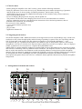
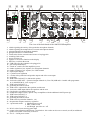
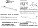
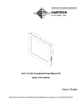
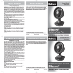
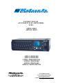
ELEKTROAKUSTYKA
INSTRUCTION OF
AUTOMATICALLY AMPLIFIERS
TYPE:
AMWL-DSP4
AMWLC-DSP4
AMWL-9DSP4/400
AMWL-9DSP4/600
AMWL-9DSP4/400+100
AMWLC-9DSP4/400
AMWLC-9DSP4/600
AMWLC-9DSP4/400+100
E L E K T R O A K U S T Y K A
J a n R d u c h
4 4 - 3 4 0 G o d ó w , ul . 1M a j a 1 9 6
t e l . 03 2 / 47 - 5 1 - 8 0 3 d o 5
www.rduch.com.pl
www.naglosnienia.com.pl
www.naglosnienia.eu
e-mail: [email protected]
1. Clues for users
- Before putting the amplifier to the 230V currency, please read the following instruction.
- Doing any unknown service to the device by any unauthorized persons makes the depriving of guarantee
and can be the cause of the worsening of technical parameters and the safety of using.
- ATTENTION! The device must be supplied from the plug-in socket with the safety circuit connected (
socket with grounding wheel).
- In case of changing the plug-in fuse, the plug must be pulled off.
- The producer can introduce some changing to the device in case of modernizations or technical
progress, without the necessity to put them into the instruction as far as the basic parameters, that are
included in this instruction, are not changed.
The accessories of the amplifier:
- service manual with the guarantee card,
- spare fuse,
- plug-in cable,
- application software CD,
2. Using and general notices.
The modern amplifiers AMC- DSP4 (Powermixer) are designed to be used in sacral buildings, large, closed areas,
conference rooms, where the high quality and the hearing of speaking is required. They are cooperating with the
50V, 70V and 100V loud speakers line and with the loud speakers set of altogether impedance > = 4 Ù.
The amplifier has got: 8 symmetrical microphone line channels to put in the dynamic, capacitive and wireless
microphones or the device with line level output and music channel to put in the record player, tuner or CD player
(LINE asymmetrical). To record, there is a separate RCA (RECORD) socket.
AMWL-DSP is a modern amplifier equipped in signaling DSP processor that enables precise correction of sound
characteristics in buildings with very difficult acoustic conditions. The amplifier activates only those microphones,
that are used in that moment, what eliminates sound surrounding influence coming from not used microphone
channels. Each 1-8 channel is equipped in symmetrical XLR input, sensitivity regulation, Phantom power.plugged
in, microphone/line switch, 100Hz high pass filter, preamplification regulation, and timbre regulation
(bas/soprano) designed in front of the case. In 1-8 channels, diodes signal the channel activity and the microphone
transposition.
3. Arrangement of elements and sockets.
13
HIGH
LOW
HIGH
14
LOW
HIGH
LOW
15
16
HIGH
DIGITAL SIGNAL PROCESSOR
7
8
9
MASTER
10
10
10
10
10
8
8
8
8
8
6
6
6
6
4
4
4
2
2
2
0
0
0
4
RECORD
EAK
MIC.
PEAK
MIC.
PEAK
PRESET 2
SETTINGS
ENTER
SPK-ZONE-LEVEL
6
POWER
ON
4
2
2
0
0
PRESET 1
LINE CD
-
+
OFF
EXIT
ELEKTROAKUSTYKA
1 2 3
4
5
6
7
8
9
10
11
12
The view of the front board of the AMWL-DSP amplifier.
3
26
27 28
29
30 31 32
XLR pin 1: GND
MIC. 4
GAIN
LEVEL
100W
100V
COM
SPK-ZONE
OUT
MIC. 3
GAIN
LEVEL
1 2 3
PIN 3: -
PIN 2: +
MIC. 2
Phantom
Mic.(on)/Line(off)
HPF 100Hz
Bal.
INFO OUT
PRESET 2
Phantom
Mic.(on)/Line(off)
HPF 100Hz
DSP OUT 2
INPUT
PANEL
PRESET
GND
LIFT
GAIN
LEVEL
1 2 3
ON
MIC. 1
GAIN
LEVEL
1 2 3
ON
Phantom
Mic.(on)/Line(off)
HPF 100Hz
34
Phantom
Mic.(on)/Line(off)
HPF 100Hz
33
1 2 3
ON
ON
GND
LIFT
MIC. 8
50V
GAIN
LEVEL
8
4
COM
MIC. 7
GAIN
LEVEL
1 2 3
DSP OUT 4
Bal.
GND
LIFT
MIX OUT
DSP OUT 1
OUTPUT 0 dB
INPUT 0 dB
PRE MASTER,EQ
Bal.
PRE MASTER
Bal.
GND
LIFT
17 18
19
20
21 22
GAIN
LEVEL
1 2 3
ON
POST MASTER,EQ
Bal.
230V~ / 50Hz
MIC. 5
1 2 3
ON
REPLACE FUSE
WITH SAME TYPE
AND RATINGS
35
GAIN
LEVEL
1 2 3
ON
400W
MIC. 6
ON
LINE IN 9
1V - 10k
Unbal.
GND
LIFT
23
24
The view of the back board of the AMWL-DSP amplifier
1- a diode signaling the activity of the particular microphone channels
2- a diode signaling the transposition of a certain microphone channel
3- gain potentiometer in microphone channels
4- gain potentiometer of LINE channel
5- Cinch socket for the external sound source to be plugged in
6- recording Cinch socket
7- presets switches on
8- a pulser to service the function on the display
9- EXIT key exit from the menu
10- USB socket for the computer to be plugged in
11- gain sum potentiometer
12- switch on/ switch off of the amplifier's power
13- timbre regulation ( bas, soprano ) for microphone channels
14- timbre regulation ( bas, soprano ) for LINE channel
15- liquid crystal display
16- 6 pointed zone regulation
17- a socket of the particular loud speaker outputs and of the zone output
18- grounding
19- XLR socket DSP OUT 4 ( Subwoofer option )
20- Jack socket: MIX OUT - symetrical output channels: 9 (Line CD), 0dB and 1-8 enable with programmer
nr: 2 (MAINSUM-2)- view on page 13.
21- XLR socket: DSP OUT 1
22- grounding disconnect switch
23- XLR socket output before the equalizer and the sum
24- Jack socket 0dB output before the equalizer and the sum
25- Cinch socket asymmetric linear input
26- loudspeaker output socket ( option! only in amplifiers with the additional 100 W power tip)
27- XLR socket: DSP OUT 3
28- XLR socket: DSP OUT 2
29- grounding disconnect switch
30- XLR socket in particular channels ( 1-8 )
31- the particular outputs sensitivity regulation
32- 3 positioned switch: 1 Phantom power on/off
2 MIC / LINE switch
3 100 Hz high pass filter on / off
33- RJ 45 socket Preset steering panel input
34- output socket informing about Preset 2 switched on- this socket can also act to control (set off) an additional
speaker circiut that is used only in Preset 2.
35- 230 V ~/ 50 Hz power socket
4
Phantom
Mic.(on)/Line(off)
HPF 100Hz
Bal.
Phantom
Mic.(on)/Line(off)
HPF 100Hz
DSP OUT 3
70V
Phantom
Mic.(on)/Line(off)
HPF 100Hz
100V
RISK OF ELECTRIC SHOCK
DO NOT OPEN
Phantom
Mic.(on)/Line(off)
HPF 100Hz
COM
25
4. Amplifier's menu control.
After amplifier's connection to 230V currency by a given cable and power input (switch no 12), (no 15) on the display,
Our company's logo appears, and after several seconds, there is a given screen.
c.d. Preset name
preset name
FEW PEOPLE
WEEK
3dB Preset 1
0dB ESA on
- 6dB AMWL
adjusted preset number
eliminator pluged in
- 12dB DSP-4
11:39
dB 27.1 C
clock
power terminal temperature
input indicators (1-4)
To service the menu, use the pulser handwheel (8) - press it, to get in the settings mode. Then, there is the next screen
“noise gate”
limiter on input 1
Noise gate
white field - cursor present position
NG-Noise Gate
input equalizer
IN 1 NG LIM1 EQ IN
IN 2
LIM2
CR
crossover
limiter on input 2
Turning the handwheel(8) left or right, there are other menu's parts ( previous or next parts). To come into the chosen
part press handwheel ( 8 ) (ENTER). To come back to the previous part press ( EXIT) ( 9 ).
The first setting part is NG - noise gate
Noise gate
Noise gate
Preset 1
0dB
ENTER
IN 1 NG LIM1 EQ IN
Threshold
-90 dB ±
IN 2
LIM2
CR
dB
0dB
Turning the handwheel (8) left or right, the value edge of the noise gate can be adjusted from -24dB to -90dB.
Another setting part is the limiter field where, the value edge can be adjusted from -30dB to +6dB and the time of the
attack: slow, medium or fast. The same can be done for the limiter no2 - LIM2.
Limiter 1
Limiter 1
Preset 1
6dB
ENTER
IN 1 NG LIM1 EQ IN
Threshold
6 dB ±
IN 2
LIM2
CR
dB
5
6dB
Attack time
Slow
Equalizer part EQ.
Input EQ
Input EQ 1
ENTER
IN 1 NG LIM1 EQ IN
IN 2
Preset 1
LIM2
PeakingEQ
Point 1
CR
28Hz
choice of one from
ten equalizer’s points
0.05oct
0.0dB
filter type choice
PeakingEQ,
LoSh6, LoSh12,
HiSh6, HiSh12
frequency filtrer width setting gain attenuation
adjustment
(0,05 ÷ 3 oct.)
settings
(-12dB ÷ +12dB)
(20Hz ÷ 21,2kHz)
Crossover part.
Crossover
Crossover
ENTER
IN 1 NG LIM1 EQ IN
Preset 1
Crossover
Input 1 do Output 4
IN 2
LIM2
CR
adjustment of output 4 to input 1 or 2
Gain part.
Volume
Volume
VOL EQ 1 DLY FBS
OUT1
VOL EQ 2 DLY FBS
OUT2
VOL EQ 3 DLY FBS
OUT3
VOL EQ 4 DLY FBS SB
OUT4
Preset 1
2
ENTER
4
3
gain adjustment of
particular inputs
1
- dB -14dB -15dB
0dB
Output equalizer part: EQ1,EQ2,EQ3,EQ4.
Output 1 EQ
Output 1 EQ
VOL EQ 1 DLY FBS
OUT1
VOL EQ 2 DLY FBS
OUT2
VOL EQ 3 DLY FBS
OUT3
VOL EQ 4 DLY FBS SB
OUT4
Preset 1
filter type choice
PeakingEQ,
LoSh6, LoSh12,
HiSh6, HiSh12
PeakingEQ
Gain adjustment
(-12dB ÷ +12dB)
ENTER
Point 1
315Hz
choice of one from five
equalizer points
0.05oct
-5.0dB
filter with adjustment
(0,05oct ÷ 3oct)
frequency settings
(20Hz ÷ 21,2kHz)
In the same way, equalizer adjustments for 2,3,4 outputs can be programmed.
Delaying part
Delay
VOL EQ 1 DLY FBS
OUT1
VOL EQ 2 DLY FBS
OUT2
VOL EQ 3 DLY FBS
OUT3
VOL EQ 4 DLY FBS SB
OUT4
ENTER
Delay
preset 1
Output 1
Output 2
Output 3
Output 4
Mode
0.0 m
6
0.0 m
0.0 m
0.0 m
m
delaying adjustments
(0 ÷ 85m)
measurements regulation
(m, cm, ms)
Elimanator part.
FB Suppressor
FB Suppressor
VOL EQ 1 DLY FBS
OUT1
VOL EQ 2 DLY FBS
OUT2
VOL EQ 3 DLY FBS
OUT3
VOL EQ 4 DLY FBS SB
OUT4
ENTER
Select out
Method
Frequency
preset 1
Output 1
phase shifter
- Hz
output choice ( on which output
the eliminator is to be off)
decoupling eliminator method choice
( adaptive, phase shifter)
frequency choice
for phase shifter method
Subwoofer part.
Subwoofer
Subwoofer
VOL EQ 1 DLY FBS
OUT1
VOL EQ 2 DLY FBS
OUT2
VOL EQ 3 DLY FBS
OUT3
VOL EQ 4 DLY FBS SB
OUT4
ENTER
LP Filter
Frequency
Slope
preset 1
off
200Hz
6dB/oct.
subwoofer turn on/off
filter’s cut off
frequency adjustment
(120 Hz ÷ 472 Hz)
filter slope steepness choice
Presets part.
Presets
Presets
O
P
T
I
O
N
PRESETS
PASSWD
RTC
GENERAL
ENTER
SERVICE
preset 1
Preset
Name
Copy preset
Reset settings
preset 1
change
start
start
Clock and date
Clock and date
PRESETS
PASSWD
RTC
GENERAL
ENTER
SERVICE
preset 1
change
Set time
Set date
change
Date table
change
Preset 2 in sunday
yes
copy of chosing preset’s settings
to the second preset
time adjustment
date adjustment
recording dates board
for preset 2
automatic change of
presetu 2 for Sunday
adjustments of the possibility of
displaying the control indicator (vertical or horizontal)
General options part.
General options preset 1
General options
O
P
T
I
O
N
renaming preset
chosen preset’s name edition
back to previous settings
Clock and date part.
O
P
T
I
O
N
preset choice
PRESETS
PASSWD
RTC
GENERAL
ENTER
SERVICE
Level meter
Mode EQ
Language
vertical
line
english
choice of displaying graphs mode EQ
(filled, line)
( language choice
polish, english)
Passwords part..
Passwords
Passwords
O
P
T
I
O
N
PRESETS
PASSWD
RTC
GENERAL
SERVICE
ENTER
Lock settings
Change password
Reset password
servicing mode
(only for servicemen)
7
preset 1
off
change
change
password saving settings
turn on/off
change of password
saving seiings
adjusted password reset - new one
is automatically
set into zeros (0000)
5. Amplifier's control settings by the computer
All settings introduced by the amplifier's control panel can be also done by the PC computer. To get the
possibility of the amplifier control by the computer, the program MWL Easy Manager must be installed ( it is
on the CD added). MWL Easy Manager program is created only for the configurations of AMWL-DSP4
series.
Licensor is not responsible for any harm of the program operation or for the wrong use of the program.
MWL Easy Manager installation instruction
I. Program MWL Easy Manager requires the installation of Microsoft. NET Framework 3.5 Service Pack 1
for Windows NT, XP, 98 system ( for Windows Vista and windows 7 systems - there is not necessary).
Installation file is on CD added. Dotnetfx35.exe platform can be downloaded from the Microsoft
II. In the catalogue VCM Driver you can find drivers for use the USB port from the amplifier AMWL-DSP4
(CDM2.04.16.exe)- also need to be installed
III. After dotnet35fx.exe installation MWL Easy program can be installed
Installation file is in Rduch MWLEasyMgr 2.0 Install/Setup.exe
IV. After the program installation, it should work automatically.
V. After switching the amplifier on , program automatically detects port, where the device is installed.
Switching the amplifier on, is not necessary- parameters can be set in the program and than can be recorded in the
File first and aflter that the amplifier can be switched on and the data can be copied. To join the amplifier with the
computer, in the menu “ Comunication”, the order “join” should be chosen.
This window appears and after choosing the device, the order “Join” should be clicked on once again .
8
settings part
particular parts of settings
place to open
“Settings panel”
To record the project to the file, the option "Record the project” (Ctrl+S) in menu "file" should be chosen.
“Limiter” fold.
handwheel to set
the edge value (dB)
“options” - Presets - preset’s name
part - “Equalizer input”.
frequency regulation
(20Hz ÷ 21,2kHz)
filter width settings
(0,05oct ÷ 3oct)
filter type choise
(PeakingEQ,
LoSh6, LoSh12,
HiSh6, HiSh12)
gain attenuation regulation
(-12dB ÷ +12dB)
9
attack time
choice field
place to record
the edge value (dB)
Crossover part - is created for ordering the output number 4 to input no 1 or no 2.
to input 1 are assigned
all inputs of the
amplifier, and to input 2
are assigned input 9
(LINE CD)
0 dB and inputs 1-8
enabled with
programmer 2
(MAINSUM-2)
menu “Options” - language - language choice (Polish, English)
“Gain part”.
gain regulation of
outputs 1 - 4.
place to record the values (dB)
“No 1 output equalizer” part.
frequency regulation
(20Hz ÷ 21,2kHz)
filter width setting
(0,05oct ÷ 3oct)
filter type choice
(PeakingEQ,
LoSh6, LoSh12,
HiSh6, HiSh12)
gain attenuation regulation
(-12dB ÷ +12dB)
10
“delay” part
delay adjustment
for particular outputs
(0m ÷ 85m)
place to record
the delay values
“Eliminator” part
eliminator’s decoupling
method choice
frequency choice for
phase shifter method
output choice, it means, on which output the eliminator is to be turn on
“Subwoofer” part
the Subwoofer works
after pressing the switch "ON"
(Subwoofer option is available
only in channel no 4)
frequency settings of Subwoofer’s filter cut off
ranged 120Hz ÷ 472Hz
subwoofer’s filter slope steepness choice
11
6. Menu s tructure of MWL Easy Manager program
MENU MWL Easy Manager
FILE
NEW PROJECT Ctrl+N
OPEN PROJECT Ctrl+O
SAVE PROJECT Ctrl+S
SAVE AS...
PRINT Ctrl+P
CLOSE
EXIT Alt+F4
COMMUNICATION
CONNECT Ctrl+Shift+C
DISCONNECT
SAVE THE SETTINGS
OPTIONS
LANGUAGE
POLISH
ENGLISH
PRESETS
PRESET’S NAME
DATE BOARD
PRESET COPY
ZERO SETTINGS
WINDOW
CASCADE
PROJECT’S NAME
HELP
ABOUT THE PROGRAM
12
7. Prioritys.
1 2 3 4 5 6 7 8
ON
Programmer nr 1
1 2 3 4 5 6 7 8
ON
Programmer nr 2
(MAINSUM 2)
1 2 3 4 5 6 7 8
ON
Programmer nr 3
(MAINSUM 1)
Programmer nr 1 - default settings: all switches (1-8) in the
top position (OFF).
Switching any of the eight switches to the bottom position
(ON) turns off the automatic in each channel. This is useful if
you want to use one channel as a linear channel (music).
ATTENTION! If you want to use priorities, the channel switch
must be in the top position (OFF).
Pict. 1
programmer channels 1-8
1 2 3 4
ON
L.MIC
ATTEN.
M.AUTO
OUT2 P.
Programmer nr 4
top position OFF
bottom position ON
Adjusting the sensitivity of the channel LINE-CD
ATTACK- switching Microphone level control switch
TIME-backup time control of active microphones
Programmer nr 2 - assignment of input channels 1-8 to the output channel mix 2 (MAINSUM 2).
Assigned to input 2 (IN2) in the DSP and the output jack socket (MIX OUT).
Programmer nr 3 - assignment of input channels 1-8 to the output channel mix 1 (MAINSUM 1).
Assigned to input 1 (IN1) in DSP.
Programmer nr 4 - default settings: switches 1 and 2 in position (OFF), switches 3 and 4 in position (ON).
Switch 1 - OUT2 PRE/POST GATE: upper position (OFF) POST GATE - all channels for MAINSUM-2 are assigned
to the automatic. Bottom position (ON) PRE GATE - signals are assigned before automatic.
Switch 2 - AUTO/MANUAL: upper position (AUTO) - mixer auto work function; bottom position (MANUAL) standard mixer work.
Switch 3 - ATTENUATION OFF: inactive microphone mute Settings, upper position - completely mute;
bottom position - mute -15 dB.
Switch 4 - LAST MIC: upper position (OFF) - recently used microphone turns off after speaking,
bottom position (ON) - recently used microphone is still active after the speaking.
ATTENTION! If you want to use a priority, this feature must be disabled (upper position OFF).
Programmer of channels(1-8) - default settings: All switches in the top position (OFF). Used to set the superiority of
microphones.
lider
1
5
deputy
2
6
3
7
4
Microphones
8
Setting of any priorities configuration: switching of any
switches in any channel's programmer causes the setting of
priority precedence of this channel over the previous
chosen channel. For example: switching in channel no 1
programmer, the switch no 4 down (ON) causes that
microphone no 1 can stop work of microphone no 4.
Lower configuration (picture no 3) shows the setting of the
priority for the microphone no 1 and no 2 (picture no 2).
The microphone no 1 has the priority over the
microphones from 2 to 8, and the microphone no 2 has the
priority over the microphones from 3 to 8, but is
subordinate to the microphone no 1. It means, that the
speeches of the microphones 3-8 can be stopped in any
time by the leader (1) or his deputy (2), but the speech of
the deputy (2) can be stopped only by the leader (1).
Pict. 2
1 2 3 4 5 6 7 8
ON
1 2 3 4 5 6 7 8
ON
1 2 3 4 5 6 7 8
ON
1 2 3 4 5 6 7 8
ON
1
2
3
4
1 2 3 4 5 6 7 8
ON
1 2 3 4 5 6 7 8
ON
1 2 3 4 5 6 7 8
ON
1 2 3 4 5 6 7 8
ON
5
6
7
8
13
Pict. 3
Lower configuration (pict. 4) shows the situation for three microphones, where each of them has the priority to two
ones left. In such a configuration, the priority goes to that microphone which is activated as the first one. So, when
he speech to tsomebody starts speaking to microphone no 2, the microphones no 1 and 3 are not active till the end
of the microphone no 2. Microphones no 1 and 3 behave analogically. Such a configuration is possible for all eight
microphones. Thanks to that, there is a situation, where only one microphone is always active and it makes
impossible for somebody else to interrupt, what is valuable for the order of the conference
1 2 3 4 5 6 7 8
ON
1 2 3 4 5 6 7 8
ON
1 2 3 4 5 6 7 8
ON
1 2 3 4 5 6 7 8
ON
1 2 3 4 5 6 7 8
ON
1 2 3 4 5 6 7 8
ON
1 2 3 4 5 6 7 8
ON
1 2 3 4 5 6 7 8
ON
1
2
3
4
5
6
7
8
Pict. 4
8. Configuration and operation of the amplifier with additional power terminal
(AMWL-9DSP/400+100).
AMWL-DSP4 amplifiers have an additional 100W power terminal (option), where
the delay can be set.
100 W terminal can be switched on output DSP OUT 1 [21], DSP OUT 2 [28],
DSP OUT 3 [27] or DSP OUT 4 [19].
It is the switch inside the amplifier. Red arrow in the picture on the right, shows where it
is. The switch is described as the DSP outputs 1-4.
SACRYSTY
13m
AMP.
The picture shows the typical use of the amplifier in that version
The main power terminal operates on one loudspeaker’s circuit
(red colour) but the other circuit (blue color)loudspeakers are
spaced. Then, it is possible to adjust demanding delay on the
DSP additional 100W power terminal, which operates on this
loudspeaker’s circuit. The additional 100W circuit can also be
activated via connector INFO OUT PRESET 2. This means
that for Preset 1, which is activated when for example in the
church are "little people" the additional 100W circuit is inactive
(break on connector INFO OUT PRESET 2). However, when
in the church are a "lot of people" for enabled Preset 2, the
additional speaker circiut 100V is activated.
An example of the AMWL-DSP4/400+100
amplifier use
13
9. AMWLC-9DSP4 amplifiers.
Mic.1
Mic.2
Mic.3
Mic.5
Mic.4
Mic.6
COMPRESSOR
EKSPANDER
COMPRESSOR
EKSPANDER
COMPRESSOR
EKSPANDER
COMPRESSOR
EKSPANDER
COMPRESSOR
EKSPANDER
COMPRESSOR
EKSPANDER
COMPRESSOR
EKSPANDER
EKSPANDER
COMPRESSOR
Each microphone channel of AMWLC-9DSP4 amplifiers is additionaly equipped with Compressor-Expander.
Practically, compressor-expander allows to reach the fixed volume level independently of the input signal level.
Compressor - expander parameters settings are fixed with switches and potentiometers that are located in the upper
cover of the amplifier.
Mic.7
Mic.8
Expander adjustment Compressor adjustment
in given channel
in given channel
Switch on/off in given channel
10. XLR microphone pin connection:
2 - hot (+ve)
2 - hot (+ve)
3 - cold (-ve)
1 - chassis ground
Symmetrical input
(operating with Phantom power
recommended)
connection3 and 1
1 - chassis grounding
Asymmetric input
( plug in for the cable to 5m length at the asymmetric input
Phantom power off! )
11. Jack pin connection:
INSERT Socket
For the feedback eliminator, the equalizer,
the expander compressor,
the delaying line to be connected
output 0 dB and input 0 dB connection
symmetrical
hot(+ve)
Asymmetric
signal input
coming back of the signal
cold (-ve)
chassis grounding
signal output
chassing
grounding
chassis grounding
chassis grounding
terminal
terminal
ring
ring
sleeve
sleeve
14
ON
OFF
4Ù
ZONE
100V
100V
100V
100V
100V
12. AMWL-9DSP amplifier operation in the sound system.
...
8Ù
...
Delay
XLR pin 1: GND
PIN 2: +
PIN 3: -
Bal.
GND
LIFT
MIC. 4
POWER: 400 Watt
GAIN
LEVEL
100W
100V
Made in Europe
COM
SPK-ZONE
OUT
MIC. 3
GAIN
LEVEL
1 2 3
MIC. 2
GAIN
LEVEL
1 2 3
ON
MIC. 1
GAIN
LEVEL
1 2 3
ON
Phantom
Mic.(on)/Line(off)
HPF 100Hz
DSP OUT 2
AMWL-9 DSP4/400+100
Phantom
Mic.(on)/Line(off)
HPF 100Hz
ELEKTROAKUSTYKA
MODEL:
Phantom
Mic.(on)/Line(off)
HPF 100Hz
INFO OUT
PRESET 2
Phantom
Mic.(on)/Line(off)
HPF 100Hz
INPUT
PANEL
PRESET
1 2 3
ON
ON
GND
LIFT
MIC. 8
50V
GAIN
LEVEL
8
4
COM
MIC. 7
GAIN
LEVEL
1 2 3
DSP OUT 4
Bal.
GND
LIFT
MIX OUT
MIC. 5
GAIN
LEVEL
1 2 3
ON
1 2 3
ON
DSP OUT 1
OUTPUT 0 dB
INPUT 0 dB
POST MASTER,EQ
Bal.
PRE MASTER,EQ
Bal.
PRE MASTER
Bal.
GND
LIFT
230V~ / 50Hz
GAIN
LEVEL
1 2 3
ON
400W
MIC. 6
ON
LINE IN 9
GND
LIFT
PANEL PRESET
PRES.2
ON
PRES.1 OFF
Power
230V
Amplifier
or
ACML
column
Amplifier
eg. external circiut
Amplifier
or
ACML
column
(delay)
Amplifier
or
ACML
column
(delay)
Amplifier
or
ACML
column
(delay)
15
Mixer
Phantom
Mic.(on)/Line(off)
HPF 100Hz
Bal.
Phantom
Mic.(on)/Line(off)
HPF 100Hz
70V
DSP OUT 3
Phantom
Mic.(on)/Line(off)
HPF 100Hz
100V
Phantom
Mic.(on)/Line(off)
HPF 100Hz
COM
RISK OF ELECTRIC SHOCK
DO NOT OPEN
CD
1V - 10k
Unbal.
13. Technical data
AMWL-9DSP4
AMWL-9DSP4
Output power (sinus)
400W, 600W, 400W+100W
Microphone inputs, symmetrical and electronic
- MIC/LINE switch
- MIC sensitivity control
- LINE sensitivity control
- impedance
- phantom power supply
- HPF filter
- bass, soprano control
inputs XLR: 1-8
yes
-40dB -15dB
-15dB +5dB
1,6 kÙ
24V DC
100 Hz, 6dB/oct.
±12dB, 100 Hz, 10 kHz,
shelving filter
green diode - aktiv channel
red diode - overdrive
input RCA: 9
-10dB
+12dB
10 kÙ
±12dB, 100 Hz, 10 kHz,
shelving filter
double, peak, on DSP
input and on power end
-90dB -25dB
±12 dB, 0,05 3oct.
20Hz 21,2kHz
LoSh6, LoSh12
HiSh6, HiSh12
Peak
±12 dB, 0,05 3oct.
20Hz 21,2kHz
LoSh6, LoSh12
HiSh6, HiSh12
Peak
of adaption; phase shift
0 - 85 m
only in AMWLC
yes
100V ,70V, 50V, 8Ù, 4Ù
6-degree from 0-100V
40 - 22 000 Hz
<0,1%
from -5°C to +40°C
443 x 135 x 340
13,5
- signaling
Universal input (mono)
- input sensivity
- impedance
- bass, soprano control
Limiter
noise gate
10-point parametric equalizer on DSP input
5-point parametric equalizer
acoustic feedback suppressor
delay line
expander- compressor in channels
preset choice
non- grounded symmetrical output
adjustable zonal output
frequency band
non-linear distortions
work temperature
measurements: width/height/depth [mm]
weight [kg]
16
RISK OF ELECTRIC SHOCK
DO NOT OPEN
AVIS: RISQE DE CHOC ELECTRIQUE !
NE PAS OUVRIR !
UWAGA
RYZYKO PORA¯ENIA PR¥DEM
NIE OTWIERAÆ
RISK OF ELECTRIC SHOCK
DO NOT OPEN
UWAGA
RYZYKO PORA¯ENIA PR¥DEM
NIE OTWIERAÆ
WARNING OF DANGEROUS
ELECTRICAL VONTAGE! IN THE
HOUSING ARE NOT PROTECTET
ELECTRONIC COMPONENTS
WHICH HAVE A HIGHT ENOUGH
CHARGE. IT CAN BE
DANGEROUS!
THE EXCLAMATION POINT IS A
FORM OF GUIDANCE IS NEEDED
IN SUPPORT AND MEINTENANCE
OF THE INSTRUMENT
CAUTION
TO PREVENT ELECTRIC SHOCK, DO NOT
REMOVE TOP COVER, NO USER
SERVICEABLE PARTS INSIDE. REFER
SERVICING TO QUALIFIED SERVICE
PERSONNEL
WARNING
TO REDUCE THE RISK OF FIRE OR ELECTRIC
SHOCK DO NOT EXPOSE THIS EQUIPMENT TO
RAIN OR MOISTURE.
17
Control card
(Noise generator) control
INPUT 0 dB Pre Master
INPUT 0 dB Post Master
Microphone – linear input
Linear input
Recording
Power output ( 40W, 8W, 50V, 70V, 100V)
100 Hz filter
Delay regulation
Feedback eliminator regulation
Zone regulation
Compressor – expander control
..................................................
Date ...........................
Typ .............................
Number ........................
Output power
P
U
Z
200W/100V/50Ù
400W/100V/25Ù
600W/100V/16,6Ù
..............................
Computer control :
Connection with MWL Control program test
Correctness of saving the settings
Factory reset
Acoustic control :
Microphone – linear input
Linear input
Phantom power
Timbre regulation of microphone – linear input
Equalizer timbre regulation
Feedback eliminator regulation
100 Hz filter
Inactive microphone mute
“LAST MIC” function
“AUTO/MANUAL” function
Priorities for particular microphone channels
Noise and hum level control
General control :
230V AC power
Fuse
Ground measurements of the device ( according to VDE 0701 norm)
Other connections and connectors control
Optical control of the whole
Notices: ...............................
...........................................
...........................................
...........................................
...........................................
Signature ...............................
18
GUARANTEE CARD NO.............................
Below mentioned, efficient and in a good condition device is given to the buyer on …………..according to the rules stated in
articles no 577-582 of the Penal Code. Rduch Elektoakustyka gives the buyer a guarantee on the proper working device for 36
months.
Name of this device ....................................................................................................
Rduch Elekroakustyka company, located in Godów, 1 Maja Street 196, tel. (032) 4751803 to 06, fax. (032) 475 18 07,
is called a producer in the further part of the contract.
I. OPERATING CONDITIONS
1. Plug – in power socket 230 V /50 Hz should have grounding or neutral grounding.
2. The device should be situated in a place with the temperature between +5ºC to +40ºC and of the
humidity between 8 to 80%.
3. The device should not be a subject to vibration, should not be placed near the sources of strong electromagnetic fields and
should be protected against the excessive sun exposure.
II. WARRANTY STATEMENTS
1. Warranty period starts from the date of selling the device by the producer.
2. In order to repair the device during the warranty period, it should be delivered to the company after the previous call or fax.
3. The producer provides 7 day repair period counted from the date of the adoption of the device to repair.
4. Requirement for a complaint is to provide the device in the original packing, with the guarantee card, to the place, where the
device was bought.
5. In case of the damage of the device during the warranty period, that are caused because of the producer, or hidden defects in
the material, the producer reserves the right to exchange the device into another one that is free of defects after having
examined the causes of the device malfunction.
III. BEYOND THE WARRANTY
1. The warranty does not cover the mechanical damage or the damage caused by the user, or the damage
caused by failure to comply with the universal principles of operation of the equipment and the
requirements stated in point no 1.
2. Mechanical damages or other ones, not associated with the operation of the device, result in loss of
warranty.
3. Tuning, regulations or the exchange of the fuses are not the subject to the warranty.
4. Producer, as the servicing part, reserves the rights to estimate and qualify the level of the damage.
5. In case of delivering the device in a good condition or the device that was not previously reported, the
servicing costs, cleaning, testing and transport costs are paid by the person or the company that
complain.
6. The guarantee card is invalid without the producer’ s signature, date or the company stamp.
..................................
Date
.....................................................
Stamp and signature
Warranty and post- warranty service
Date
Stamp and serviceman
signature
Notices
19