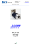
1
Absolute Rotary Encoder
with Profibus-DP-Interface
DPC1B version
User Manual
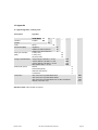
1 General ............................................................ 3 1.1 Absolute Rotary Encoder............................... 3 1.2 Profibus technology ....................................... 4 2 Installation ...................................................... 5 2.1 Settings in the connection cap ....................... 5 2.1.1 Station address ....................................... 5 2.1.2 Bus termination ....................................... 5 2.2 Connecting bus lines and power supply ........ 6 5.1.2 Desired measuring units ........................18 5.1.3 Desired Measuring units reference ........19 5.1.4 Activate commissioning mode ...............20 5.1.5 Shorter Diagnostics ...............................20 5.1.6 Software-limit switch ..............................20 5.1.7 Physical impulses ..................................21 5.1.8 Encoder type .........................................22 5.1.9 Velocity time base .................................22 5.2 Data exchange in normal operation .............23 5.3 Commissioning mode ..................................24 2.4 Assignment for M12 connectors (AH58B1DP-072) ........................................................... 7 5.3.1 Setting the counting direction ................24 5.3.2 Teach-In Start........................................25 5.3.3 Teach-In Stop ........................................25 5.3.4 Preset value...........................................26 2.5 Connecting the screen................................... 8 6 Diagnostic messages ...................................27 2.3 Connecting-up the connection cap with cable
glands .................................................................. 6 2.6 Instructions for mechanical installation and
electrical connection of the angular encoder ....... 8 3 Device Configuration ..................................... 9 3.1 Overview – Configuration principle ................ 9 3.2 Overview encoder configurations functionality........................................................ 10 3.3 Encoder configurations - data format........... 11 4 Class 1 and Class 2 profile .......................... 12 4.1 Parameter settings....................................... 12 4.1.1 Code sequence ..................................... 13 4.1.2 Class 2 functionality .............................. 13 4.1.3 Commissioning diagnostics ................... 13 4.1.4 Scaling function ..................................... 13 4.1.5 Measuring units per revolution .............. 13 4.1.6 Total measuring range .......................... 14 4.2 Data exchange in normal operation ............. 15 4.2.1 Transferring the process value .............. 15 4.2.2 Preset function ...................................... 15 5 Special versions 2.1 and 2.2 ....................... 17 5.1 Parameter .................................................... 18 5.1.1 Activate manufacturer-specific
parameters ..................................................... 18 Page 2
6.1 Overview ......................................................27 6.2 Supported diagnostic messages ..................28 6.2.1 Extended diagnostics header ................28 6.2.2 Memory error .........................................28 6.2.3 Operating status ....................................28 6.2.4 Encoder type .........................................28 6.2.5 Singleturn resolution ..............................28 6.2.6 Number of revolutions............................28 6.2.7 Operating time warning..........................28 6.2.8 Profile version........................................28 6.2.9 Software version....................................28 6.2.10 Operating time .....................................28 6.2.11 Zero offset ...........................................29 6.2.12 Programmed resolution .......................29 6.2.13 Programmed total resolution................29 6.2.14 Serial number ......................................29 6.3 Status indication by the LEDs in the
connection cap...................................................30 7 Configuring with STEP 7 ..............................31 7.1 Installing the GSD file ..................................31 7.2 Configuring the encoder...............................32 7.3 Selecting the encoder version......................33 7.4 Setting the parameters.................................34 BEI Sensors Profibus Manual serie M
Revision 03/10
8 Technical Data .............................................. 37 8.3 Mechanical Data .......................................... 38 10.2 Further encoder configurations ..................43 10.2.1 Version 2.0 Multiturn...........................43 10.2.2 Version 1.1 Multiturn...........................43 10.2.3 Version 1.0 Multiturn...........................43 10.2.4 Class 2 Multiturn ‚DX-Version’ .............43 8.4 Environmental Conditions ............................ 38 10.3 FAQ absolute encoder Profibus .................44 9 Dimensioned Drawings................................ 39 10.4 Definitions ..................................................45 10 Appendix ....................................................... 41 11 Index ..............................................................47 10.1 Type designation / ordering code............... 41 12 Revision index ..............................................48 8.1 Electrical Data.............................................. 37 8.2 Certificates................................................... 37 Specifications are subject to change without
notice
Technical specifications, which are described in
this manual, are subject to change due to our
permanent strive to improve our products.
1
Publication:
Version:
March 2010
4.5
General
This
manual
describes
installation
and
configuration of the Absolute Rotary Encoder with
Profibus DP interface. The device meets the
requirements of a Profibus Slave according to the
PROFIBUS standard. It is certified by the “Profibus
Nutzerorganisation” in Germany.
1.1 Absolute Rotary Encoder
Basic principle of the absolute measurement is the
optical scanning of a transparent disk with code
print. The code disk is connected to the shaft that
is to be measured. By evaluating the code and two
additional incremental signals the absolute position
Revision 03/10
of the shaft can be determined with a resolution of
up to 65536 steps per revolution (16 bits).
So-called Multiturn-devices use reduction gears
and further code disks to determine the absolute
BEI Sensors Profibus Manual serie M
Page 3
shaft position over up to 16384 revolutions (14
bits).
The position value is calculated in an integrated
microprocessor and transmitted over the Profibus.
1.2 Profibus technology
PROFIBUS is an international, open, nonproprietary fieldbus standard which is defined in
the international standards EN 50170 and EN
50254. There are three different versions: Profibus
DP, Profibus-FMS and Profibus-PA.
absolute
encoders are designed for the DP version. They
support all usual baud rates up to 12 MBaud.
Besides manufacturer-specific functions, the
devices support the classes 1 and 2 according to
the Profile for Absolute Encoders (this device
profile can be ordered under part number 3.062
from the “Profibus Nutzeroganisation”). Further
information
about
profibus
(functionality,
manufacturer, products), standards and device
profiles are available from the PNO:
Page 4
Profibus Nutzerorganisation (PNO)
Haid-und-Neu-Straße 7
D-76131 Karlsruhe
Tel.: ++49 (0) 721 / 96 58 590
Fax: ++49 (0) 721 / 96 58 589
www.profibus.com
BEI Sensors Profibus Manual serie M
Revision 03/10
2
Installation
The Absolute Encoder is connected with a
connection cap. This cap is connected to the
encoder with a 15-pin-D-Sub connector and can be
removed by loosening two screws on the backside
of the encoder. Bus lines and power supply are led
into the cap via cable glands and connected to
terminal blocks.
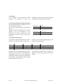
2.1 Settings in the connection cap
2.1.1 Station address
2.1.2 Bus termination
The station (node) address is set by using the
rotary switches in the cap. The values (x 10 or x 1)
for the switches are marked at the switch. Possible
addresses are between 0 and 99. Each address
can only be used once in the network. The station
address is read in when switching on the power
supply. An address change by the Master
(“Set_Slave_Add“) is not supported.
If the encoder is connected at the end or beginning
of the bus line the termination resistor must be
ON
A
+
B
A
ON
ON
device X
last device
78
901
+
The bus is only correctly terminated when the
encoder is connected to the connection cap. If the
encoder must be changed during operation, a
separate active bus termination should be used.
23
23
78
901
456
456
Revision 03/10
R
R
Note
The outgoing bus line is disconnected if the
resistor is switched on!
R
B
switched on (slide switch in position “ON”).
x10
x1
BEI Sensors Profibus Manual serie M
Page 5
2.2 Connecting bus lines and power supply
B
A
+
B
A
+
R
ON
Clamp
Description
B (left)
Bus line B (Bus in)
A (left)
Bus line A (Bus in)
-
0V
+
10 – 30 V
B (right)
Bus line B (Bus out)
A (right)
Bus line A (Bus out)
-
0V
+
10 – 30 V
B
A
+
B
A
+
The power supply has to be connected once (no
matter which clamps). If the terminating resistor is
switched on, the outgoing bus lines are
disconnected.
2.3 Connecting-up the connection cap
with cable glands
Remove screw, sealing and cone from the cable
gland. Remove 55 mm of the cable sheath and 50
mm of the shielding. About 5 mm of the wires
should be stripped. Put screw and sealing on the
cable. The cone should be mounted under the
shielding according to the figure. Put the whole
cable into the cable gland and tighten the screw.
Note: If a combined cable (power supply and bus
lines in one cable) is used the large cable diameter
can lead to problems. For these cases offers
connection caps with larger cable glands (refer to
product catalogue).
55 mm
50 mm
5 mm
Page 6
5 mm
BEI Sensors Profibus Manual serie M
Revision 03/10
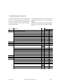
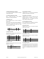
2.4 Assignment for M12 connectors (AH58-B1DP-072)
Connecting the data lines and the power supply
5pin connector (left)
R
ON
B
A
+
B
A
78
not connected
2
Bus line A (Bus in)
3
not connected
4
Bus line B (Bus in)
5
not connected
456
78
1
5pin female socket (center)
23
23
456
x10
Description
+
901
901
Pin
Pin
Description
x1
1
not connected
2
Bus line A (Bus out)
3
not connected
4
Bus line B (Bus out)
5
not connected
4pin connector (right)
2
3
5
1
1
4
4
5
2
2
1
3
3
4
Data lines and power supply are connected to
5 pin M12 connector
5 pin M12 female socket
4 pin M12 connector
Revision 03/10
Pin
Description
1
10 – 30 V DC
2
not connected
3
0V
4
not connected
If the terminating resistor is switched on the
outgoing bus lines are disconnected.
BEI Sensors Profibus Manual serie M
Page 7
2.5 Connecting the screen
To achieve the highest possible noise immunity
shielded cables should be used for data
transmission. The shield should be connected to
ground on both ends of the cable. In certain cases,
a compensation current might flow over the shield.
Therefore a potential compensation cable is
recommended.
2.6 Instructions for mechanical installation and electrical connection of the angular encoder
The following points should be observed:
Do not drop the angular encoder or subject it
to excessive vibration. The encoder is a
precision device.
Do not open the angular encoder housing
(this does not mean that you cannot remove
the connection cap). If the device is opened
and closed again, it can be damaged and dirt
may enter the unit.
The angular encoder shaft must be
connected to the shaft to be measured
through a suitable coupling (full shaft
version). This coupling is used to dampen
vibrations and imbalance on the encoder
shaft and to avoid inadmissible high forces.
Suitable couplings are available.
Although absolute encoders are rugged,
when used in tough ambient conditions, they
should be protected against damage using
suitable protective measures. The encoder
should not be used as handles or steps.
Only qualified personnel may commission
and operate these devices. These are
personnel who are authorized to commission,
Page 8
ground and tag devices, systems and circuits
according to the current state of safety
technology.
It is not permissible to make any electrical
changes to the encoder.
Route the connecting cable to the angular
encoder at a considerable distance or
completely separated from power cables with
their associated noise. Completely shielded
cables must be used for reliable data transfer
and good grounding must be provided.
Cabling,
establishing
and
interrupting
electrical connections may only be carried-out
when the equipment is in a no-voltage
condition. Short-circuits, voltage spikes etc.
can result in erroneous functions and
uncontrolled statuses which can even include
severe personnel injury and material damage.
Before powering-up the system, check all of
the electrical connections. Connections,
which are not correct, can cause the system
to function incorrectly. Fault connections can
result in severe personnel injury and material
damage.
BEI Sensors Profibus Manual serie M
Revision 03/10
3
Device Configuration
The Absolute Encoder with Profibus-Interface can
be programmed according to the needs of the
user. The GSD-file has to be installed in the used
software tool. The user has the possibility to
choose
different
encoder
configurations.
Parameters and functionality depend on the
selected
encoder
configuration.
-Absolute
Encoders Type „MHM5-MHK5-DPC1B-XXXXXXXX-0CC“ support all configurations described in
the following, i.e. there is no functionality limitation
due to the hardware. Additionally to the
configurations „Class 1“ and „Class 2” (according
to the Profile for Encoders) the Encoder offers
configurations with manufacturer-specific functions.
By choosing a certain encoder configuration
parameter and configuration data are determined.
These data are stored in the profibus master. They
are transmitted to the slave (encoder) when the
profibus network is starting up („DDLM_Set_Prm“).
It is not possible to change parameters or
configuration during the normal operation of the
device (exception: “Commissioning Mode”, see
chapter 5.3).
After receiving configuration and parameter data
the absolute encoder enters the normal operating
mode
(cyclic
data
transmission
–
„DDLM_Data_Exchange“). In this mode the
process values (e.g. the position value) are
transmitted. Data length and format are determined
by the user when selecting a certain encoder
configuration.
3.1 Overview – Configuration principle
Revision 03/10
BEI Sensors Profibus Manual serie M
Page 9
3.2 Overview encoder configurations - functionality
Designation
Cyclic communication
Programmable
parameters
Additional functions
Class 1
Singleturn
Position value - 16 bit Input
Code sequence
-
Class 1
Multiturn
Position value - 32 bit Input
Code sequence
-
Class 2
Singleturn
Position value - 16 bit Input
Preset value - 16 bit Output
Code sequence
Scaling factor
Preset function
Class 2
Multiturn
Position value - 32 bit Input
Preset value - 32 bit Output
Code sequence
Scaling factor
Preset function
2.1 Singleturn
Position value (32 bit Input)
Preset value / Teach-In
(32 bit Output)
Code sequence
Scaling factor
Shorter Diagnostics
Limit switches
Preset function
Commissioning mode
2.1 Multiturn
Position value (32 bit Input)
Preset value / Teach-In
(32 bit Output)
Code sequence
Scaling factor
Shorter Diagnostics
Limit switches
Preset function
Commissioning mode
2.2 Singleturn
Position value (32 bit Input)
-
Preset value / Teach-In
(32 bit Output)
-
Code sequence
Scaling factor
Shorter Diagnostics
Limit switches
Velocity time base
Preset function
Commissioning mode
Velocity Output
Code sequence
Scaling factor
Shorter Diagnostics
Limit switches
Velocity time base
Preset function
Commissioning mode
Velocity Output
Velocity
(16 bit Input)
2.2 Multiturn
Position value (32 bit Input)
-
Preset value / Teach-In
(32 bit Output)
-
Velocity
(16 bit Input)
Page 10
BEI Sensors Profibus Manual serie M
Revision 03/10
3.3 Encoder configurations - data format
Designation
Configuration Input words
Hex
Dec. (Encoder ->
Master)
Output words
(Master ->
Encoder)
Class 1 Singleturn
(According to Profile)
D0
208
1
0
Class 1 Multiturn
(According to Profile)
D1
209
2
0
Class 2 Singleturn
(According to Profile)
F0
240
1
1
Class 2 Multiturn
(According to Profile)
F1
241
2
2
2.1 Singleturn
F1
241
2
2
2.1 Multiturn
F1
241
2
2
2.2 Singleturn
F1
D0
241
208
2
1
2
2.2 Multiturn
F1
D0
241
208
2
1
2
Description
Chapter
Page
4
12
5
17
The following encoder configurations are still supported for reasons of downward compatibility, but
should not be used for new projects (description: see Appendix):
Class 2 Multiturn
„DX-Version“
F1
241
2
2
10.2.4
43
1.0 Multiturn
D3
211
4
0
10.2.3
43
1.1 Multiturn
D3
E1
211
225
4
0
0
2
10.2.2
43
2.0 Multiturn
F1
D0
241
208
2
1
2
10.2.1
43
Revision 03/10
BEI Sensors Profibus Manual serie M
Page 11
4
Class 1 and Class 2 profile
The encoder versions Class 1 and Class 2 are
defined by the working group encoder in the
„Profibus Nutzerorganisation“ in the “Profile for
Encoders” (available from the PNO, Order No.
3.062).
4.1 Parameter settings
The following table contains an overview of the
parameters according to the Profile for Encoders
and the structure of the parameter telegram.
(Usually it is not necessary for the user to know the
details of the structure – the parameters are set in
user-friendly forms in the operator software tool.)
Octet (= byte) No.
Parameter
1 ... 8
Profibus Standard Parameters
9
Code sequence
Bit Nr.
Details
0
Class 2 functionality
1
Section 4.1.2, Page 13
Commissioning Diagnostics
2
Section 4.1.3, Page 13
Scaling function
3
Section 4.1.4, Page 13
Reserved
4
Reserved
5
Not used for Class 1 and Class 2
6
7
10
Measuring units per revolution
Section 4.1.5, Page 13
Total measuring range
Section 4.1.6, Page 14
...
13
14
...
17
18
Reserved (Profile)
...
25
Page 12
26
Not used for Class 1 and Class 2
...
(Refer to versions 2.1 und 2.2)
BEI Sensors Profibus Manual serie M
Revision 03/10
4.1.1 Code sequence
The parameter „code sequence“ defines the
counting direction of the position value. The code
increases when the shaft is rotating clockwise
(CW) or counter-clockwise (CCW) (view onto the
shaft). The code sequence is defined in bit 0 of
octet 9:
Octet 9 Bit 0
Direction of rotation when viewing the shaft
Code
0
Clockwise (CW)
Increasing
1
Counter-clockwise (CCW)
In Class 1 this is the only parameter that can be set.
Increasing
4.1.2 Class 2 functionality
Using this switch Class 2 encoders can be
restricted to the functionality of Class 1, i.e. the
scaling parameters are disabled. To use the class
2 functionalities bit 1 in octet 9 has to be set.
Octet 9 Bit 1
Class 2 functionality
0
Switched off
1
Switched on
4.1.3 Commissioning diagnostics
This function has no significance for the encoder.
4.1.4 Scaling function
The parameter „scaling function“ enables the
scaling parameters „resolution per revolution“ and
„total resolution“. This switch should always be
activated if functions of class 2 (or even higher
classes 2.1 and 2.2) are to be used.
Octet 9 Bit 3
Scaling function
0
Switched off
1
Switched on
4.1.5 Measuring units per revolution
The parameter „measuring units per revolution“ is
used to program a desired number of steps over
one revolution. If the value exceeds the basic
(physical) resolution of the encoder, the output
code is no longer in single steps. Starting with
generation “B1” the encoder indicates a parameter
error (LED) and it will not enter the data exchange
mode.
With high resolution encoders it may be necessary
to divide the value into high and low word
(depending on the software tool), refer to page 35.
Octet
10
11
12
13
Bit
31 - 24
23 - 16
15 - 8
7–0
Data
231 to 224
223 to 216
215 to 28
27 to 20
Desired measuring units per revolution
Revision 03/10
BEI Sensors Profibus Manual serie M
Page 13
4.1.6 Total measuring range
Octet
14
15
16
17
Bit
31 – 24
23 – 16
15 - 8
7-0
Data
231 to 224
223 to 216
215 to 28
27 to 20
Programmed total measuring range in steps
The parameter „total measuring range“ is used to
adapt the measuring range of the encoder to the
real measuring range of the application. The
encoder counts up until the position value has
reached the programmed total resolution and starts
with 0 again.
Example: 100 steps are programmed for each
revolution (parameter „measuring units per
revolution“) and the total resolution is set to 12800.
Then the encoder counts up to 11799, starts with
“0” again after 128 revolutions, counts up to 11799,
and so on.
Note: With many software tools it is necessary to
divide the value into high and low word, refer to
page 35.
When choosing the total resolution the following
rule has to be observed:
If “steps per revolution” are set to “n” the parameter total resolution must not cause periods longer than
the maximum (physical) number of revolutions (see type label), i.e. that the programmed total resolution
of a 4096 revolution multiturn encoder must be less than 4096 x the programmed number of steps per
revolution (the programmed total resolution of a 16384 revolution multiturn encoder must be less than
16384 x the programmed number of steps per revolution):
Total resolution < measuring units per revolution x real number of revolutions (physical)
If this rule is disregarded the encoder will indicate a parameter error and it will not enter the data
exchange mode.
With older versions a further rule had to be
observed (see below). If this rule was ignored,
problems occurred when using the device in
endless operation (when crossing the physical
zero point). With new devices (software version
3 Generation A1 or higher) this problem is
solved by an internal software routine. For that
reason the 2nd rule can be ignored if a new
device is used.
Note: The internal software routine only works if the
encoder is in operation. If it is necessary to turn the
encoder shaft more than 1024 revolutions without
power supply this can lead to problems (the internal
routine will not work without power supply). In this
case the following rule should be observed even with
new devices:
The period, i.e. “Total resolution” / “measuring units” per revolution must be an integer and it must fit an
integer number of times (integer multiple) into 4096. So the following equation must apply:
(4096 x measuring units per revolution) / Total resolution = integer
Page 14
BEI Sensors Profibus Manual serie M
Revision 03/10
For multiturn devices with 16384 revolution the rule
is as follows (if it is necessary to turn the encoder
shaft more than 4096 revolutions without power
supply):
The period, i.e. “Total resolution” / “measuring units” per revolution must be an integer and it must fit an
integer number of times (integer multiple) into 16384. So the following equation must apply:
(16384 x measuring units per revolution) / Total resolution = integer
4.2 Data exchange in normal operation
The „DDLM_Data_Exchange mode“ is the normal
operation mode of the device. On request the
encoder transfers the current (position) value to the
master. The encoder can also receive data from
the master (e.g. the preset value in the class 2
configuration).
4.2.1 Transferring the process value
The multiturn encoder transmits the current
position value as a 32-bit-value (double word) to
the master.
Word
Word 1
Word 0
Function
Bit
Process value
31
30 29
28
27
26
25
24
23
22
21
20
19 18
17
16
15
14 13
12
11
10
9
8
7
6
5
4
3
2
1
0
0 0 X X X X X X X X X X X X X X X X X X X X X X X X X X X X X X
The Singleturn encoder uses a 16-bit-value (word)
for data transmission.
4.2.2 Preset function
Using the preset function it is possible to adapt he
encoder zero point to the zero point of the
application. When using this function the current
encoder position value is set to the desired preset
value. The integrated microcontroller calculates the
internal zero point shift. It is stored non-volatile in
an EEPROM (takes less than 40 ms).
The preset value is activated if bit 31 in the
(peripheral) output double word is set to 1 (rising
edge). As the preset function is used after
Revision 03/10
receiving the scaling parameters the preset value
refers to the scaled position value.
BEI Sensors Profibus Manual serie M
Page 15
Data bits
Bit
Master
31
30
29
28
27
26
25
24
23
22
21
20
19
18
17
16
15
14
13
12
11
10
9
8
7
6
5
4
3
2
1
0
1 0 Transfer of the required position value (= preset value)
MHM5
MHM5
0 0 New = required position value is transferred
Master
Master
0 0 Reset bit 31 – normal mode
MHM5
MHM5
0 0 New = required position value is transferred
Master
If high precision is required the preset function
should only be executed if the encoder shaft is not
moving. If the shaft moves quickly during the
Note for Singleturn devices
The procedure is similar with the singleturnversion: Here Bit 15 is used to activate the preset
value. With high resolution singleturn encoders (16
Bit) it is not possible to set preset values > 32767
(15 bit), as the MSB is used to activate the preset.
Page 16
preset procedure, this can result in offsets
(because of bus delay times).
If this functionality is needed the user has to
choose one of the manufacturer specific -encoder
versions (in these classes the singleturn position is
transmitted as 32-bit-value).
BEI Sensors Profibus Manual serie M
Revision 03/10
5
Special versions 2.1 and 2.2
The manufacturer-specific encoder configurations
2.1 and 2.2 offer (in addition to the functions
according to the Profile for Encoders) features
such as commissioning mode, velocity output and
software limit switches.
Octet (byte)
The following table gives an overview of the used
parameters and the structure of the parameter
telegram.
Usually it is not necessary to know these details as
the parameters are set with user-friendly software
tools.
Parameter
Details
No.
Section
Page
Profibus Standard Parameters
Code sequence
0
4.1.1
13
Class 2 functionality
1
4.1.2
13
Commissioning Diagnostics
2
4.1.3
13
Scaling function
3
4.1.4
13
Reserved
4
5.1.1
18
No.
1 .. 8
9
Bit
Reserved
5
Activate manufacturer-specific parameters (octet 26)
6
Reserved
7
10 .. 13
Desired measuring units (refer to: octet 26 bit 0 and 1)
5.1.2
18
14 .. 17
Total measuring range
4.1.6
14
18 .. 25
Reserved
26
Reference for the desired measuring steps
5.1.3
19
0
1
Activate commissioning mode
2
5.1.4
20
Shorter Diagnostics
3
5.1.5
20
Reserved
4
Activate lower limit-switch
5
5.1.6
20
Activate upper limit-switch
6
5.1.6
20
Activate octets 27-39
7
5.1.1
18
27 .. 30
Lower limit switch
5.1.6
20
31 .. 34
Upper limit switch
5.1.6
20
35 .. 38
Physical impulses
5.1.7
21
39
Reserved
0
Encoder type (Single-/Multiturn)
1
5.1.8
22
Reserved
2
Reserved
3
5.1.9
22
Time base velocity
4
5
Revision 03/10
Reserved
6
Reserved
7
BEI Sensors Profibus Manual serie M
Page 17
5.1 Parameter
In the following the manufacturer specific
parameters are described in detail. The
parameters according to the Profile for Encoders
are supported too, description: see chapter 4.
5.1.1 Activate manufacturer-specific parameters
The manufacturer-specific parameter byte 26 is
activated with bit 6 in octet 9.
Bit 7 in octet 26 activates further parameter bytes
(27-39).
Usually this happens automatically if the encoder
versions 2.1 or 2.2 are selected. It is only
important for the user to observe this if the
parameters are entered “manually” (directly using
hex-code).
Octet 9 Bit 6
Octet 26
0
Deactivated
1
Activated
Octet 26 Bit 7
Octet 27 – 39
0
Deactivated
1
Activated
5.1.2 Desired measuring units
The parameter „desired measuring units“ is used to
program any required number of steps over 1
Octet
10
Bit
31 - 24
Data
31
2
11
12
23 - 16
24
to 2
23
2
revolution, over the whole measuring range or over
a part of the measuring range.
13
15 - 8
16
15
to 2
2
7–0
8
to 2
27 to 20
Desired measuring units
The reference for the desired measuring units is
specified with the parameter „Desired measuring
units reference“ (cp. 5.1.3). If “per revolution” is
selected the measuring range can be adapted with
the parameter “total measuring range”. Please
observe the rules in section 4.1.6.
Page 18
Note: With many software tools it is necessary to
divide the value into high and low word, refer to
page 35.
BEI Sensors Profibus Manual serie M
Revision 03/10
5.1.3 Desired Measuring units reference
With this parameter the reference for the desired
measuring units (cp. 5.1.2) is determined, either
per revolution
per maximum total resolution
per number of physical impulses
Desired measuring units per revolution
In this case the position value increases by the
programmed number of steps (desired measuring
units) over one revolution.
Additionally the parameter “total resolution” is used
to achieve an adaptation of the measuring range
(cp. 4.1.6).
Desired measuring units per maximum total
measuring range
The parameter „desired measuring units“ refers to
the complete measuring range of the encoder, i.e.
the encoder gives out the programmed number of
measuring units over the whole measuring range
(4096 revolutions with the multi turn encoder).
Desired measuring units per physical impulses
The desired measuring units refer to the physical
impulses entered in octets 35-39 (cp.5.1.7).
Physical impulses means: The real value that is
read internally from the code disc (e.g. 4096 steps
per revolution with a standard 12-bit-encoder).
With that option it is possible to set gearing factors
freely.
Reference
Octet 26 Bit 0
Octet 26 Bit 1
Per revolution
0
0
Per maximum total measuring range
1
0
Per physical impulses
(= steps specified in octets 35-38)
0
1
Revision 03/10
BEI Sensors Profibus Manual serie M
Page 19
5.1.4 Activate commissioning mode
Bit 2 in octet 26 activates the commissioning
mode. This is a special mode with the option to set
further parameters in the data-exchange –mode
(additional to the preset value). In the
commissioning mode a „Teach-In“ can be carried
out, i.e. the gearing factor can be determined
directly in the machine. In this special mode
(indicated by the flashing green LED) the
parameters set in the system configuration are
ignored by the encoder. It uses parameters stored
in an internal EEPROM instead.
The commissioning mode can be used durably, but
it is recommended to transfer the parameters
determined with the Teach-In into the system
configuration. Then the encoder should be used in
“normal” operation mode – so it is possible to
exchange the device without a new Teach-In.
A detailed description of the commissioning mode
can be found in section 5.3.
Octet 26 Bit 2
Commissioning mode
0
Switched off
1
Switched on
Octet 26 Bit 3
Diagnostics
0
Standard = 57 bytes
1
Reduced = 16 bytes
5.1.5 Shorter Diagnostics
Some Profibus masters, especially older ones,
have problems with the full diagnostic data length
(57 bytes). The encoder offers the option to
reduce the diagnostic data length to 16 bytes. If
Class 1 is used the standard diagnostic data length
is 16 bytes.
5.1.6 Software-limit switch
Two positions can be programmed. If the position
value falls below the lower limit switch or exceeds
the higher limit switch, bit 27 in the 32-Bit-processvalue is set to 1. Between these limit switches bit
27 is set to 0. The limit switches can be set to any
value, but the parameter “total measuring range”
must not be exceeded. The limit switches are
activated with bits 5 and 6 in octet 26.
Note: With many software tools it is necessary to
divide the values into high and low word, refer to
page 35.
Octet
27
28
29
30
Bit
31 - 24
23 - 16
15 – 8
7-0
Data
231 to 224
223 to 216
215 to 28
27 to 20
Lower limit switch (in measuring steps, related to the scaled value)
Page 20
BEI Sensors Profibus Manual serie M
Revision 03/10
Octet
31
32
33
Bit
31 - 24
23 - 16
15 – 8
31
Data
2
24
23
to 2
2
16
15
to 2
2
34
7-0
8
27 to 20
to 2
Upper limit switch (in measuring steps, related to the scaled value)
Octet 26 Bit 5
Lower limit switch
0
Deactivated
1
Activated
Octet 26 Bit 6
Upper limit switch
0
Deactivated
1
Activated
5.1.7 Physical impulses
Octet
35
36
37
Bit
31 - 24
23 – 16
15 – 8
Data
31
2
24
to 2
23
2
16
to 2
15
2
38
7-0
8
to 2
27 to 20
Physical impulses
This parameter is evaluated if the reference for the
„desired measuring units“ is „physical impulses“
(cp. 5.1.3).
With the „physical impulses“ it is possible to set a
gearing factor freely. The user defines the output
steps („desired measuring steps”) over a part of
the measuring range. This option is helpful to
program scaling factors that result in a non-integer
number of steps over 1 revolution.
Example:
Problem: The position value has to increase by
400 steps over 3 revolutions.
Revision 03/10
With the reference „steps per revolution“ it is
impossible to program that scaling factor (it would
be necessary to set the parameter „desired
measuring steps“ to 133.33; this is not possible
because the parameter must be an integer value).
Solution:
Choose „physical impulses“ as reference for the
„desired measuring units“.
Now the number of physical measuring steps over
the desired measuring range is determined. For
this the actual (physical) resolution of the encoder
(type label) is used. For our example this would be
(with a standard encoder, 12 Bit resolution):
BEI Sensors Profibus Manual serie M
Page 21
4096 steps/revolution x 3 revolutions = 12288
steps
Enter this value (12288) as „physical impulses“ and
set the „desired measuring units“ to 400. Now the
encoder increases the position value by 400 steps
on a measuring range of 12288 physical steps (3
revolutions).
Note: With many software tools it is necessary to
divide the value into high and low word, refer to
page 35.
5.1.8 Encoder type
The encoder type (Singleturn or Multiturn) is
specified in bit 1 octet 39. Generally this bit is set
automatically if the encoder version is selected.
The user only has to take care of this parameter if
the parameters are set “manually” in hex-code.
Octet 39 Bit 1
Type
0
Singleturn
1
Multiturn
5.1.9 Velocity time base
With this parameter the user can choose the time
base for the velocity output (version 2.2). The time
base is specified in bits 4 and 5 of octet 39.
Time base
Page 22
Bit 4
Steps / second
0
0
Steps / 100 ms
1
0
Steps / 10 ms
0
1
RPM (revolutions per minute)
1
1
Bit 5
BEI Sensors Profibus Manual serie M
Revision 03/10
5.2 Data exchange in normal operation
With the manufacturer-specific versions 2.1 and
2.2 the process value generally is transmitted as
32-bit-value (peripheral double word). Apart from
25 bits used for the position value the 7 other bits
are used as status bits. The output double word
contains the preset value and control bits.
Absolute encoders model series “MHM5” might
have (physical) position values > 25 Bit. The
manufacturer specific versions do not support the
ID
MHM5
F1 hex
Master
D0 hex
Status + position value
24
Status + 2
Master
position values > 25 Bit. The upper digits will be
overwritten by the status bits. If the versions are
used with encoders with a total (physical)
resolution > 25 Bit, the user has to assure that the
position value is scaled to a maximum output value
< 33554432. If position values > 25 Bit are
necessary class 2 should be used.
If version 2.2 is used the current velocity is
transmitted in an additional (peripheral) input word.
MHM5
23
16
2 -2
Velocity
15
8
7
0
2 -2
2 -2
215 - 28
27 - 20
215 - 28
27 - 20
Preset value + control bits
24
Control + 2
223 - 216
Meaning of the different status bits:
Bit 28
Bit 27
Bit 26
Bit 25
Meaning
Ready
0 = encoder is not ready for operation
1 = encoder is ready for operation
Mode
0 = commissioning mode
1 = normal mode
Software limit switch
0 = lower limit switch ≤ current position value ≤ upper limit switch
1 = current position value > upper limit switch or
current position value < lower limit switch
Code sequence
0 = increasing clockwise (view onto the shaft)
1 = increasing counter clockwise (view onto the shaft)
Revision 03/10
BEI Sensors Profibus Manual serie M
Page 23
5.3 Commissioning mode
If the commissioning mode is activated in the
encoder parameters, the scaling factor can be
determined directly in the machine by a „Teach-In“.
The commissioning mode is indicated by the
flashing green LED and bit 26 in the input double
word (bit 26 set to 0).
If the encoder starts up in commissioning mode the
parameters in the system configuration (code
sequence, scaling) are ignored. Parameters stored
in an internal EEPROM are used instead. If code
sequence or scaling factor are modified in
commissioning mode, the new values will be
stored non-volatile and the encoder works with this
new parameters.
The proceeding in commissioning mode is as
follows:
The encoder is installed in the machine /
system.
-
-
The commissioning mode is activated
(parameter settings, cp. 5.1.4)
The counting direction is changed (if
necessary).
Machine / system is to be moved to the start
position.
The Teach-In-Start command is transmitted to
the encoder.
Machine / system is to be moved to the stop
position.
With the Teach-In-Stop command the desired
number of steps is transferred to the encoder.
Set the preset value.
The parameters in the system configuration
are set to the values determined with the
Teach-In procedure.
Commissioning
mode
is
deactivated
(parameter settings).
5.3.1 Setting the counting direction
If the encoder is operating in commissioning mode,
the counting direction (code sequence) can be
changed online. The current code sequence is
indicated with bit 28 in the 32-bit-process value (0:
Status bits
Bit
Master
31
30
29
28
0 0 0 1
increasing clockwise / 1: increasing counter
clockwise). With bit 28 in the output double word
the counting direction can be changed.
Data bits
27
26
25
24
23
22
21
20
19
18
17
16
15
14
13
12
11
10
9
8
7
6
5
4
3
2
1
0
0 0 0 Changing the counting direction by setting bit 28
MHM5
MHM5
0 0 0 0/1 0 0 1 Encoder sends acknowledgement (new counting direction) in bits 0 and 28
0/1
Master
Master
0 0 0 0
0 0 0 Changeover is completed by reset bit 28
MHM5
MHM5
0 0 0 0/1 X 0 1 Output process value with changed counting direction
Master
The counting direction is stored non-volatile in an internal EEPROM.
Page 24
BEI Sensors Profibus Manual serie M
Revision 03/10
5.3.2 Teach-In Start
After the machine / system has been moved to the
start-position the Teach-In-Start command is
Status bits
Bit
Master
transmitted to the encoder. The device now starts
the internal calculation of a new scaling factor.
Data bits
31
30
29
28
27
26
25
24
23
22
21
20
19
18
17
16
15
14
13
12
11
10
9
8
7
6
5
4
3
2
0
1
0
0
0
0
0
Start the Teach-In by setting bit 30 to 1
0
1
0
X X 0
1
Acknowledgement of the encoder by setting bit 30 to 1
0
0
0
0
0
0
Reset bit 30
0
1
0
X X 0
1
Non-calculated position value is transmitted (gearing factor = 1, no offset)
1
0
MHM5
MHM5
Master
Master
0
MHM5
MHM5
Master
Note: The scaling factor is set to 1; the zero point
shift is set to zero.
5.3.3 Teach-In Stop
After moving the machine / system to the stopposition the Teach-In-Stop command is send.
Together with this command the desired number of
steps over the moved measuring range is
transmitted. The user has to observe that the
physical resolution is not exceeded (e.g. 20000
steps on a quarter of a revolution). Positive and
negative directions are taken into account
automatically, also the crossing of the physical
zero point. Note: The measuring range must not
exceed the half physical measuring range of the
encoder (i.e. a maximum of 2047 revolutions for a
Status bits
Bit
Master
multiturn device with 4096 revolutions and a
maximum of 8181 revolutions for the 14-Bitmultiturn).
After receiving the Teach-In-Stop command the
encoder transmits the calculated total resolution.
This value should be noted and later (when
switching the device to normal mode) entered into
the parameter settings.
After this Teach-In procedure the encoder operates
with the new gearing factor (which is stored nonvolatile in the internal EEPROM).
Data bits
31
30
29
28
27
26
25
24
23
22
21
20
19
18
17
16
15
14
13
12
11
10
9
8
7
6
5
4
3
2
1
0
0
1
0
0
0
0
Number of desired measuring steps (on the traversed measuring range)
0
1
1
X X 0
1
Transfer of the total resolution (should be noted)
0
0
0
0
0
0
Reset bit 29
0
0
0
X X 0
1
Output of the current position value, scaled with the new gearing factor
0
MHM5
MHM5
Master
Master
0
MHM5
MHM5
Master
Revision 03/10
BEI Sensors Profibus Manual serie M
Page 25
In order to replace the encoder later without a new
Teach-In procedure, the total measuring range
determined with the Teach-In should be transferred
into the system configuration. For this the „total
resolution“ must be entered into the parameter field
„desired measuring units“ (cp. 5.1.2) and the
reference (cp. 5.1.3) must be set to “maximum total
measuring range“. When setting the parameters it
should be observed that the code sequence is
correct (the setting of the counting direction in
commissioning mode has to be transferred to the
system
configuration).
Subsequently
the
commissioning mode can be switched off and the
encoder can be used in normal mode.
5.3.4 Preset value
versions 2.1 or 2.2 there is an acknowledgement
(bit 31 in the input double word is set to 1):
The preset function is similar to the procedure
described in section 4.2.2. There is only one
difference: When using the manufacturer-specific
Status bits
Bit
Master
31
30
29
28
Data bits
27
26
25
24
23
22
21
20
19
18
17
16
15
14
13
12
11
10
9
8
7
6
5
4
3
2
1
0
1 0 0 0 0 0 0 Transfer of the required position value (= preset value)
MHM5
MHM5
1 0 0 0 0 0 1 New = required position value is transferred
Master
Master
0 0 0 0 0 0 0 Reset bit 31 – normal mode
MHM5
MHM5
0 0 0 0 0 0 1 New = required position value is transferred
Master
Page 26
BEI Sensors Profibus Manual serie M
Revision 03/10
6
Diagnostic messages
6.1 Overview
On request of the master the encoder transmits
diagnostic data ("DDLM_Slave_Diag"). The
diagnostic data length is 57 bytes (Exception:
shorter diagnostics, cp. 5.1.5). The format of the
diagnostic data is according to the Profibus
Standard (octets 1-6) respectively according to the
Profile for Encoders (starting from octet 7).
Diagnostic function
Data type
Diagnostics - octet number
Class
Station status 1 (ref. to: Profibus Standard)
Octet
1
1
Station status 2 (ref. to: Profibus Standard)
Octet
2
1
Station status 3 (ref. to: Profibus Standard)
Octet
3
1
Diagnostic master address
Octet
4
1
PNO identification number
Octet
5, 6
1
Extended diagnostic header
Octet String
7
1
Alarm messages
Octet String
8
1
Operating status
Octet String
9
1
Encoder type
Octet String
10
1
Resolution per revolution (Hardware)
Unsigned 32
11 - 14
1
Number of revolutions (Hardware)
Unsigned 16
15, 16
1
Additional alarm messages
Octet String
17
2
Supported alarm messages
Octet String
18, 19
2
Warnings
Octet String
20, 21
2
Supported warnings
Octet String
22, 23
2
Profile version
Octet String
24, 25
2
Software version
Octet String
26, 27
2
Operating time
Unsigned 32
28 - 31
2
Zero offset
Unsigned 32
32 - 35
2
Manufacturer-specific: offset value
Unsigned 32
36 - 39
2
Programmed resolution per revolution
Unsigned 32
40 - 43
2
Programmed total resolution
Unsigned 32
44 - 47
2
Serial number
ASCII String
48 - 57
2
Revision 03/10
BEI Sensors Profibus Manual serie M
Page 27
6.2 Supported diagnostic messages
6.2.5 Singleturn resolution
In the following the different diagnostic messages
are described in detail.
Diagnostic bytes 11-14 contain the real (physical)
resolution per revolution of the encoder.
6.2.1 Extended diagnostics header
6.2.6 Number of revolutions
Byte 7 contains the length of the extended
diagnostics (including header itself).
Diagnostic bytes 15 and 16 contain the real
(physical) number of revolutions of the encoder.
Standard values are 1 for singeturn and 4096
(resp. 16384) for multiturn devices.
6.2.2 Memory error
Bit 4 in diagnostic byte 8 is used to indicate a
memory error.
Memory error means that the internal EEPROM of
the encoder no longer works correctly and that it
cannot be guaranteed that values (e.g. offset
value) are stored non-volatile.
6.2.7 Operating time warning
Bit 4 in diagnostic byte 21 indicates an operating
5
time warning. The bit is set after 10 hours.
6.2.8 Profile version
Diagnostic bytes 24 and 25 contain the profile
version of the encoder.
Bit
Definition
0
1
4
Memory error
(defective EEPROM)
No
Yes
Byte
24
Bit
15 – 8
Data
6.2.3 Operating status
Diagnostic byte 9 contains certain parameters (set
in the system configuration).
7
25
0
2 -2
27 - 20
Revision No.
Index
6.2.9 Software version
Diagnostic bytes 26 and 27 contain the software
version of the encoder.
Bit
Definition
0
1
0
Direction of rotation
CW
CCW
1
Class 2 functionality
Off
On
Octet
26
2
Diagnostic routine
Off
On
Bit
15 – 8
3
Scaling function
Off
On
7–0
Data
7
27
7-0
0
2 to 2
27 to 20
Revision No.
Index
6.2.4 Encoder type
Diagnostic byte 10 contains the encoder version
(singleturn or multiturn).
Byte 10
Definition
0
Singleturn encoder
1
Multiturn encoder
Page 28
6.2.10 Operating time
The operating time of the encoder can be read out
from diagnostic bytes 28 to 31. If the encoder is
connected to the power supply the operating time
is stored in an EEPROM every six minutes in 0.1 h
steps.
BEI Sensors Profibus Manual serie M
Revision 03/10
6.2.11 Zero offset
6.2.14 Serial number
The zero offset is output in diagnostic bytes 32 to
35.
Diagnostic bytes 48-57 are intended for a serial
number.
With the current version the serial number is not
saved in the encoder, the bytes contain the default
value 2A hex.
6.2.12 Programmed resolution
The programmed resolution per revolution is output
in diagnostic bytes 40 to 43. The value is only valid
if the scaling factor is based on the parameter
„resolution per revolution“ (cp. 5.1.3).
6.2.13 Programmed total resolution
The programmed, respectively calculated total
resolution is output in diagnostic bytes 44-47.
Revision 03/10
BEI Sensors Profibus Manual serie M
Page 29
6.3 Status indication by the LEDs in the connection cap
Two LEDs are implemented in the connection cap.
They optically indicate the status of the encoder in
the profibus network.
The red LED is used to display errors, the green
one displays the status of the encoder. Both LEDs
can have one of three possible conditions: dark,
bright and flashing. Seven of the nine possible
combinations are used to indicate a special
condition.
LED rot /
red
LED grün /
green
If there are any problems with starting-up the
system, the state of the LEDs can give important
information about the error cause.
No.
Red LED
Green LED
Status / possible cause
1
Dark
Dark
No power supply.
2
Bright
Bright
Encoder is ready for operation but it has not received any
configuration data after power on.
Possible causes: address setting incorrect, Bus lines not connected
correctly.
3
Bright
Flashing
Parameter or configuration error.
The encoder receives configuration or parameter data with
incorrect length or inconsistent data.
Possible cause: parameter value “total measuring range” too high
4
Flashing
Bright
The encoder is ready for operation but not addressed by the master
(e.g. incorrect address in configuration).
5
Bright
Dark
Encoder has not received any data for a longer period (about 40
sec.). Possible cause: bus line has been interrupted.
6
Dark
Bright
Normal operation in data exchange mode
7
Dark
Flashing
Commissioning mode
Page 30
BEI Sensors Profibus Manual serie M
Revision 03/10
7
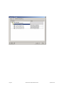
Configuring with STEP 7
In the following the configuration of the encoder
with the configuration tool STEP 7 is shown
exemplarily. In this example STEP 7 Version 5.1
and the CPU 315-2DP (profibus-master integrated)
are used. If there are questions about other
software tools please contact the manufacturer.
7.1 Installing the GSD file
If encoders are used for the first time it is
necessary to install the GSD file („FRAB4711.gsd“)
to take over the encoder into the hardware
catalogue of the tool:
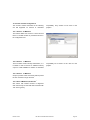
Choose “Install New GSD” in the “HW Config”window of the project (menu item “Options”) and
select the GSD-file (“FRAB4711.gsd”).
After the successful installation of the GSD file the
encoder can be found in the hardware catalogue
under „PROFIBUS-DP“ – „Additional Field
Devices“ – „Encoders“ – „ Encoder“.
In order to represent the encoder with a bitmap in
STEP7 the bitmap file „MHM5DPxxn.bmp“ has to
be installed. The procedure is the same as with the
GSD file.
Revision 03/10
BEI Sensors Profibus Manual serie M
Page 31
7.2 Configuring the encoder
After inserting the Profibus master system in the
hardware configuration (“Insert” – “Master
System”) the encoder can be chosen from the
hardware catalogue and added to the profibus
network: Select the device “ Encoder” and drag it
with the mouse to the network (or choose the
network and double click the “ encoder”).
Now the slave address has to be entered (has to
be equal to the address setting in the connection
cap).
Page 32
BEI Sensors Profibus Manual serie M
Revision 03/10
7.3 Selecting the encoder version
As described in chapter 3 the functionality of the
encoder depends on the selected encoder version.
After the “ encoder” has been added to the network
the desired encoder version can be selected. For
Revision 03/10
this, one of the modules listed under encoder has
to be dragged to Slot 1 in the displayed
configuration table of the encoder.
BEI Sensors Profibus Manual serie M
Page 33
7.4 Setting the parameters
Select the encoder in the hardware configuration
and double click slot one in the configuration table
of the encoder. The dialog „Properties – DP slave“
appears. The input and output addresses can be
changed (if desired). To set the encoder
parameters the tab “Parameter Assignment” has to
be selected.
After choosing the „Device-specific parameters“
the different parameters (depend on the encoder
version) can be set.
If several possibilities are offered for one
parameter the parameters list is opened by double
Page 34
clicking on it. Numerical values have to be entered
directly. The example shows the parameters of
encoder version 2.2, the version with the highest
functionality.
BEI Sensors Profibus Manual serie M
Revision 03/10
Due to the old versions of software tool STEP7 32-bit parameter values (e.g. total measuring range,
software limit switches) have to be divided into high and low word. This is not necessary with the new
STEP7 versions and our actual GSD file.
Example for the old GSD file:
Decimal
Hexadecimal
129600
00 01 FA 40
Hexadecimal
Decimal (to be entered)
High word
00 01
1
Low word
FA 40
64064
The decimal value „1“ has to be entered into the high word parameter field, the value 64064 into the low
word parameter field.
Or:
Divide the value by 65536; enter the integer part of the result into the high word parameter field, the
remainder into the low word field.
129600 / 65536 = 1.977539
129600 – 1 x 65536 = 64064
integer part = 1
remainder = 64064
high word = 1
low word = 64064
It is also possible to enter the parameters directly as hexadecimal code. However this is very complicated
and it should be avoided if possible.
Revision 03/10
BEI Sensors Profibus Manual serie M
Page 35
Page 36
BEI Sensors Profibus Manual serie M
Revision 03/10
8
Technical Data
8.1 Electrical Data
General design
According to DIN VDE 0160
Protective Class III, degree of pollution 2, over voltage Category II
Power supply voltage
10 - 30 V DC (absolute limit values) *
Power drain
max. 2.5 Watt
Current consumption
max. 230 mA with 10 V DC, max. 100 mA with 24 V DC
EMC
Emitted interference according to EN 61000-6-4
Noise immunity according to EN 61000-6-2
Bus connection
Electrically isolated by optocouplers
Interface
Line driver according to RS 485
Baud rates
12 MBaud, 6 MBaud, 3 MBaud, 1.5 MBaud, 500 kBaud, 187.5 kBaud,
93.75 kBaud, 45.45 kBaud, 19.2 kBaud, 9.6 kBaud
Resolution
Standard: 4096 steps/revolution
(optional up to 65536 steps/revolution)
Number of revolutions
1 (Singleturn)
4096 or 16384 (Multiturn)
Accuracy of division
½ LSB (up to 12 Bit), 2 LSB (up to 16 Bit)
Step frequency
max. 800 kHz
Code
Binary
Operating live
16,73 / 13,55 years (at 40°C, Single- / Multi-Turn, with connection cap)
MTTF d
146521 h / 118694 h (at 40°C, Single- / Multi-Turn, with connection cap)
Addressing
Using rotary switches in the connection cap
* Note
The absolute angular encoder may only be operated with safety extra low voltage according to EN 50 178!
8.2 Certificates
UL proved
File E251481
RoHS
According EG-Direktive 2002/95/EG
Reach
Not affected
ISO 9001
Revision 03/10
BEI Sensors Profibus Manual serie M
Page 37
8.3 Mechanical Data
Housing
Aluminum, optional stainless steel
Lifetime
Dependent on shaft version and shaft loading – refer to table
Max. shaft loading
Axial 40 N, radial 110 N
Inertia of rotor
30 gcm2
Friction torque
3 Ncm / 5 Ncm (without / with shaft sealing)
RPM (continuous operation)
Singleturn:
max. 12,000 RPM
Multiturn:
max. 6,000 RPM
Shock (EN 60068-2-27)
100 g (halfsine, 6 ms)
Permanent shock (EN 60028-2-29)
10 g (halfsine, 16 ms)
Vibration (EN 60068-2-6)
10 g (10 Hz ... 2,000 Hz)
Weight (standard version)
Singleturn:
Multiturn:
600 g
Weight (stainless steel version)
Singleturn:
1,100 g
Multiturn:
1,200 g
Flange
550 g
Synchro (S)
Clamp (C)
Hollow shaft (B)
Shaft diameter
6 mm
10 mm
10 mm
15 mm
Shaft length
10 mm
20mm
20 mm
-
-
-
-
15 mm / 30 mm
hollow shaft depth min. / max.
Minimum (mechanical) lifetime
Lifetime in 108 revolutions with F a / F r
Flange
40 N / 60 N
40 N / 80 N
40 N / 110 N
C10 (Clamp flange 10 x 20)
247
104
40
S10 (Synchro flange 10 x 20)
262
110
42
S6 (Synchro flange 6 x 10) without shaft sealing
822
347
133
S6 (Synchro flange 6 x 10) with shaft sealing: max. 20 N axial, 80 N radial
8.4 Environmental Conditions
Operating temperature
- 40 .. +85°C
Storage temperature
- 40 .. + 85 °C
Humidity
98 % (without liquid state)
Protection class (EN 60529)
Casing side: IP 65
Shaft side: IP 64 (optional with shaft sealing: IP66)
Page 38
BEI Sensors Profibus Manual serie M
Revision 03/10
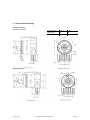
9
Dimensioned Drawings
Synchro flange (S)
available in 2 versions
Synchro flange
d / mm
l / mm
Version S06
6 f6
10
Version S10
10 h8
20
Clamp flange (C)
Revision 03/10
BEI Sensors Profibus Manual serie M
Page 39
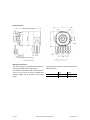
Hollow shaft (B)
Mounting instructions
The clamp ring may only be tightened if the shaft of
the driving element is in the hollow shaft.
The diameter of the hollow shaft can be reduced to
12mm, 10 mm or 8 mm by using an adapter (this
reducing adapter can be pushed into the hollow
shaft).
Page 40
Allowed shaft movements of the drive element are
listed in the table.
axial
radial
static
± 0.3 mm
± 0.5 mm
dynamic
± 0.1 mm
± 0.2 mm
BEI Sensors Profibus Manual serie M
Revision 03/10
10 Appendix
10.1 Type designation / ordering code
Description
Interface
Version
Code
Revolutions (Bits)
Steps per revolution
(Bits)
Flange / Shaft Diameter
Mechanical options
Connection
Type Key
MHM5 MHK5 DP
Profibus
DP
C1
B-
__
__-
___
_-
___
C1
Binary
B
Singleturn
00
Multiturn (4,096 revolutions)
12
Multiturn (16,384 revolutions)
14
4,096 (0.09°)
12
8,192 (0.04°)
13
65,536 (0.005°)
16
Clamp Flange, Full Shaft, 10 mm
C10
Synchro Flange, Full Shaft, 6 mm
S06
Synchro Flange, Full Shaft, 10 mm
S10
Blind Hollow Shaft, 15 mm
B15
Without
Shaft sealing (IP66)
Stainless steel version *
Customized
With connection cap AH58-B1DP-3PG
With connection cap AH58-B1DP-2M20
With connection cap AH58-B1DP-072 (3x M12 Anschluss)
Without connection cap **
0
S
V
C
H3P
H2M
H3B
HCC
Standard = bold, further models on request
Revision 03/10
BEI Sensors Profibus Manual serie M
Page 41
Accessories and Documentation
Description
Article name
Article number
Aluminium housing with 3x M12 cable glands for
cable diameters between 6,5 – 9 mm
AH 58-B1DP-3PG
0246370340
Stainless steel housing with 3x M12 cable glands for
cable diameters between 6,5 – 9 mm
AH 58-B1DP-3PG-VA
0246370355
AH58-B1DP-072
0246370359
AH 58-B1DP-2M20
0246370344
Shaft coupling ** Drilling: 10 mm / 10 mm
Drilling: 6 mm / 6 mm
GS 10
GS 06
29100450
29100350
Clamp disc ** 4 pcs / encoder
SP 15
32400155
Clamp half-ring **2 pcs / encoder
SP H
32400152
Reducing Ring ***
RR12
RR10
RR8
32220291
32220292
32220295
Aluminium housing with 3x M12 connectors
Aluminium housing with 2x M20 cable glands for
cable diameter between 9 – 13 mm
**
15 mm auf 12 mm
15 mm auf 10 mm
15 mm auf 8 mm
not for hollow shaft
*** only for hollow shaft
Page 42
BEI Sensors Profibus Manual serie M
Revision 03/10
10.2 Further encoder configurations
The encoder versions described in the following
are still supported for reasons of downward
compatibility. They should not be used in new
projects!
10.2.1 Version 2.0 Multiturn
This version differs from version 2.2 in the fact that
there is a smaller number of parameters shown in
the configuration tool.
10.2.2 Version 1.1 Multiturn
This is an older version formerly called Class „3“. It
is similar to class 2 but has an additional velocity
output. It is still available for reasons of downward
compatibility but it should not be used for new
projects.
10.2.3 Version 1.0 Multiturn
Output of position value and velocity without preset
function. Should no longer be used.
10.2.4 Class 2 Multiturn ‚DX-Version’
Old version with reduced number of diagnostic
data. Should only be used with older encoders with
“DX” in the type key.
Revision 03/10
BEI Sensors Profibus Manual serie M
Page 43
10.3 FAQ absolute encoder Profibus
Problem
There are problems with the profibus network (bus
error, no answer from the encoder) if one of the
following profibus masters is used:
-
SIEMENS S5-95U
Master Interface SIEMENS IM 308-B
Softing PROFIboard
Allen Bradley 1785 PFB/B
Mitsubishi A1SJ 71PB92D
Solution
If it is possible the maximum number of diagnostic
data per slave should be increased in the master.
If this is not possible the encoder can either be
used as a „class 1“ encoder (diagnostic data length
16 bytes) or one of the manufacturer-specific
versions ( 2.1 or 2.2) can be used with reduced
diagnostics (cp. 5.1.5).
Possible cause
The masters do not support the full diagnostic data
length (57 bytes).
Problem
If COM PROFIBUS Version 5.0 is used it is not
possible to insert the encoder into the hardware
configuration if the PLC S5-95U is used.
Cause
The S5-95U does not support the full diagnostic
data length (57 bytes). COM PROFIBUS V5.0
checks
the
GSD-parameter
Problem
PLC and master are switched on, bus is active, but
there is no answer from the encoder.
Possible solutions
First of all the state of LEDs in the connection cap
should be checked (cp. section 6.3). Possibly this
can give hints to the cause of the problem.
Both LEDs dark: Check power supply!
Page 44
„Max_Diag_Data_Len=57“ and prevents the
configuration of both devices together.
Solution
Use COM PROFIBUS Version 3.3, choose one of
the manufacturer-specific -versions ( 2.1 or 2.2)
and activate the reduced diagnostics.
If COM PROFIBUS V5.0 is to be used the
configuration of the encoder is only possible with a
modified
GSD
file
(slave
key
„Max_Diag_Data_Len“ has to be changed).
Both LEDs bright:
Encoder is ready but receives no configuration or
parameter telegrams. Check the address setting in
the connection cap. Check the connection of the
bus lines (BUS IN / BUS OUT). Check the
hardware configuration in your software tool.
Red LED bright, green LED flashing:
Parameter error! Check parameters, e.g. the rules
for setting the total measuring range (cp. 4.1.6)
BEI Sensors Profibus Manual serie M
Revision 03/10
Problem
Sporadic bus errors
The resistance value must be about 110
parallel 220 ).
(220
Possible cause
Terminating resistors not correct
Possible cause
EMC problems
Possible solution
Check terminating resistors!
The resistors of 220
must be switched on at
the beginning and at the end of the bus
segment. Switch off the power supply and
measure the resistance between the terminals A
and B in the connection cap.
Possible solutions
Is the used baud rate acceptable for the length
of the bus lines? Try to use lower baud rate if
necessary. Check the connection of the cable
shield in the connection cap. Are all cables and
conductions laid according to EMC rules?
10.4 Definitions
Address
A number, which is assigned to each node, no matter whether it is a master or
slave. The address is set (non-volatile) in the connection cap using rotary
switches.
AWC
Abbreviation: Absoluter Winkelcodierer (German) = Absolute Rotary Encoder
Baud rate
Data transfer rate specified as the number of bits transferred per second (baud
rate = bit rate).
Bus Node
Device, which can send, receive or amplify data via the bus.
Configuring
When the master configures the slave the properties of the slave are specified
(e.g. number of input and output bytes).
DDLM
Direct Data Link Mapper. Interface between Profibus-DP functions and the
encoder software.
DDLM_Data_Exchange Operating status of the bus, for standard data transfer.
DDLM_Set_Prm
Operating status of the bus, configuration and parameter are transmitted
„DDLM_Slave_Diag“
Operating status, diagnostic data are requested from the slave (e.g. encoder).
Diagnostics
Identification, localization, classification, display, additional evaluation of faults,
errors and messages.
Freeze
This is a master command to the slave. This allows the master to freeze the
states of the inputs (for example of the absolute angular encoder) to their
current value. The input data are only updated again after reception of the
UNFREEZE command.
Revision 03/10
BEI Sensors Profibus Manual serie M
Page 45
GSD file
File that contains slave-specific characteristics. The GSD file is supplied by the
manufacturer of the profibus slave. The GSD format is standardized (defined in
GSD specifications), so configuration tools of various manufacturers can use
the GSD files.
Master
“Active” device in the network that can send data without request. Controls the
data interchange.
Octet
Data unit of 8 bits = 1 byte
Profibus
Process Fieldbus, European fieldbus standard, which is defined in the
PROFIBUS Standard (EN 50170). This specifies functional, electrical and
mechanical characteristics for a bit-serial fieldbus system.
Slave
Bus node, that only sends data on request of the master. Absolute rotary
encoders are always slaves.
Terminating resistor
Resistor that terminates the bus cable; terminating resistors are always
required at the end of a cable or segment.
Type file
Similar to GSD file, is used with older configuration software tools.
Word
Expression used for a data unit of two bytes.
Page 46
BEI Sensors Profibus Manual serie M
Revision 03/10
11 Index
B
L
Bus termination ................................................. 5
LEDs................................................................30
Low word .........................................................35
C
Class 1............................................................ 12
Class 2............................................................ 12
Code sequence............................................... 13
Commissioning mode ..................................... 24
Configuring the encoder.................................. 32
Connecting
bus lines ........................................................ 6
power supply ................................................. 6
Connection cap
settings .......................................................... 5
M
Mechanical Data..............................................38
Memory error...................................................28
O
Operating time warning ...................................28
Ordering code..................................................41
P
Data format ..................................................... 11
Desired measuring units ................................. 18
Diagnostic messages...................................... 27
Dimensioned Drawings ................................... 39
Parameter settings ..........................................12
Parameters......................................................34
Physical impulses ................................ 17, 19, 21
Preset function ................................................15
Preset value ....................................................26
Profibus Nutzerorganisation ..............................4
Profile for Absolute Encoders ............................4
E
S
Electrical Data................................................. 37
Encoder configurations ................................... 10
further .......................................................... 43
Endless operation ........................................... 14
Environmental Conditions ............................... 38
Shorter Diagnostics .........................................20
Software-limit switch........................................20
Station address .................................................5
Status bits........................................................23
STEP 7 ............................................................31
F
T
FAQ ................................................................ 44
Teach-In Start..................................................25
Teach-In Stop..................................................25
Technical Data ................................................37
Total measuring range.....................................14
Type designation .............................................41
Type file...........................................................46
D
G
GSD file .......................................................... 46
Installation ................................................... 31
H
High word........................................................ 35
V
Velocity
Time base ....................................................22
I
Installation......................................................... 5
Revision 03/10
BEI Sensors Profibus Manual serie M
Page 47
12 Revision index
Revision
Date
Revision
Changed to new type key DPC, new technical drawings, new connection cap
9.4.2010
03/10 4.5
Page 48
BEI Sensors Profibus Manual serie M
Revision 03/10