1
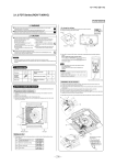
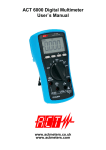
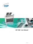
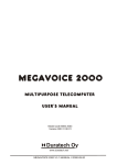
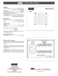
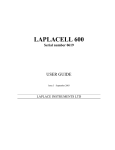
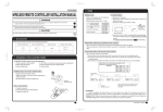
(e) FDFW Series (RCN-FW-E)
PGF012D002
WIRELESS KIT INSTALLATION MANUAL
WARNING
Use specified wire for electrical wiring, fasten the wiring to the terminal securely, and hold the cable securely in order not to apply
unexpected stress on the terminal.
Loose connections or hold could result in abnormal heat generation or fire.
Turn off the power source during servicing or inspection work.
If the power is supplied during servicing or inspection work, it could cause electric shock and injury by the operating fan.
Shut off the power before electrical wiring work.
It could cause electric shock, unit failure and improper running.
CAUTION
DO NOT install it in the following places.
(1) Places exposed to direct sunlight
(2) Places near heat devices
(3) High humidity places
(4) Hot surface or cold surface enough to generate condensation
(5) Places directly exposed to oil mist or steam
(6) Places where the receiver is influenced by the fluorescent lamp
(especially inverter type) or sunlight.
(7) Places where the receiver is affected by infrared rays of any
other communication devices
(8) Places where some object may obstruct the communication with
the remote controller
DO NOT leave the wireless kit without the cover.
In case the cover needs to be detached, protect the receiver with a packaging box or bag in order to keep it away from water and dust.
Attention
• Instruct the customer how to operate it correctly referring to the instruction manual.
• For the installation method of the air conditioner itself, refer to the installation manual enclosed in the package.
1 Accessories
Please make sure that you have all of the following accessories.
Control ASSY
Display label
Screw for display
Wireless remote
controller
AAA dry cell battery
(RO3)
Remote controller
holder
Wood screw
for holder
1
1
2
1
2
1
2
2 Preparation before installation
Setting on site
To change setting
The interface PCB has the following
switches to set the function.
Default setting is shown with
mark.
SW1-1 Prevents interference
during plural setting
ON : Normal (1ch)
OFF : Customized (2ch)
SW1-2 Receiver master/slave
setting
ON : Master
OFF : Slave
SW1-3 Buzzer valid/invalid
ON : Valid
OFF : Invalid
SW1-4 Auto restart
ON : Valid
OFF : Invalid
SW1-5 Indication for error
ON : Valid
OFF : Invalid
SW1-6 Not in use
ON : – – –
OFF : – – –
1. Remove the upper case of the interface PCB assy.
2. Change the switch setting on PCB.
SW1
Receiver
Terminal
Switch
Interface PCB
upper case
1 2 3 4 5 6
ON
OFF
Default settings
NOTE
When SW1-1 is turned to off position, change the wireless remote
controller setting.
For the method of changing the setting, refer to Setting to avoid
mixed communication on page 372.
1
-
370 -
2
L
3 How to install the control assy
The control assy (Receiver and Interface PCB assy) can be installed inside the indoor unit.
After turning off the power and confirming safety, execute as follows.
1 Remove Inlet panel
a) Pull the inlet panel towards you at the upper side of both
sides, and detach the latches.
b) Remove the retainer string from the front panel.
c) Remove the inlet panel.
CAUTION
When removing the inlet
panel, be careful not to
drop it on your feet.
2 Remove Front panel
a) Remove the fixing screw. (5 pieces)
b) Detach the latches at the upper side of the front panel. (3 places)
If difficult to remove the latch, detach the latch portion by using
straight screw driver, for example.
c) Move the lower part of the front panel towards you.
d) Detach the latches at the lower side of the front panel. (6 places)
Latch
Latch
3 Remove Display label and stick on Display label
a) Peel off the original display label, on the upper side. (★ Mark)
Press the back side of label, then the label floats.
b) Stick the attached display label on the same location.
Pull
CAUTION MUST change the display label.
If the display label is not changed, the receiver can not receive the signal from the remote controller.
4 Install Control assy
a) Fix the receiver on the indoor unit, by the attached screw.
(2 pieces, refer to figure 1)
Make sure that the claw of the receiver hungs on the claw
of the indoor unit control box. (Refer to figure 2)
b) Put the interface PCB assy on the indoor unit control box.
Put the interface PCB assy securely in the innermost
location, when installing the front panel. (Refer to figure 3)
c) Fix the wiring on indoor unit control box by the clips.
(3 places, refer to figure 4)
d) Fix the terminal of the wiring assy (for X, Y) on the lower
side terminal block of the indoor unit. (Non-polarity)
fig. 1
fig. 2
Screw
Screw
Claw
fig. 4
fig. 3
Clip
Terminal block
(X, Y)
5 Put back Front panel
a) Place the front panel over the indoor unit.
b) Hang the latches on the lower side of the front panel. (6 places)
c) Hang the latches on the upper side of the front panel. (3 places)
d) Tighten the fixing screw. (5 pieces)
6 Put back Inlet panel
a) Put the lower side of the inlet panel on the front panel.
b) Hang the retainer string on the claw of the front panel.
c) Snap the latch of the inlet panel upper side into the front panel.
4 How to install the wireless remote controller
CAUTION DO NOT install it in the following places.
1. Places exposed to direct sunlight
2. Hot surface or cold surface enough to generate condensation
3. Places near heat devices
4. Places directly exposed to oil mist or steam
5. High humidity places
6. Uneven surface
Installation tips for the remote controller holder
How to insert batteries
• Adjust and keep the holder
up right.
• Tighten the screw to the end
to avoid scratching the
remote controller.
• DO NOT attach the holder
on plaster wall.
1 Detach the back lid.
2 Insert the batteries.
(two AAA batteries)
3 Reattach the back lid.
Ensure the correct
polarity when
inserting.
Wood screw
Holder for remote controller
1
2
-
371 -
5 Function setting of interface PCB and wireless remote controller
Master/Slave setting when using plural remote controllers
Up to two wireless kit or wired remote controller can be installed in one indoor unit group.
When two wireless kit or wired remote controller are used, it is necessary to change setting on the PCB to slave.
Switch
Wired remote controller: SW1
Wireless kit: SW1-2
Setting
Master
Contents
Master remote controller
Slave
Slave remote controller
Setting to avoid mixed communication
In case of plural setting, check the operation distance of wireless remote controller, and avoid mixed
communication.
Refer to 7 Wireless remote controller operation distance on page 373 about the operation distance.
It is necessary to change setting of interface PCB and wireless remote controller.
(1) Interface PCB
Set SW1-1 to “OFF” position.
Radio prevention mode
(2) Wireless remote controller
Pressing ACL and AIR FLOW button at the same time or inserting the batteries with
pressing AIR FLOW button will customize the signal.
Setting to disable the Auto mode operation
VRF system (except heat recovery 3-pipe system) cannot be operated in Auto mode.
Make sure to set the remote controller for the models so as not to be able to choose
Auto mode.
Pressing ACL and MODE button at the same time or inserting the batteries with
pressing MODE button will make auto mode operation.
ATTENTION
When the batteries are removed, the setting will return to the default setting. Please
make sure to reset it when the batteries are replaced.
CAUTION
Instruct the customer to set the mentioned above when replacing the batteries.
(How to set is also mentioned in the user’s manual attached on the air conditioner.)
Auto mode operation setting
6 Wiring
Control plural indoor units with one remote controller
Up to 16 indoor units can be connected.
1 Connect indoor units with each other with 2-core wires. As
for size, refer to the following note.
2 The receiver wires must be connected only with the indoor
unit that will be operated by the remote controller directly.
3 Use the rotary SW1 and SW2 provided on the indoor unit
PCB (Printed circuit board) to set unique remote control
communication address avoiding duplication.
Restrictions on the thickness and length of wire
(Maximum total extension 600m.)
Standard Within 100m x 0.3mm2
Within 200m x 0.5mm2
Within 300m x 0.75mm2
Within 400m x 1.25mm2
Within 600m x 2.0mm2
Outdoor unit
No.01
Outdoor unit
No.02
Indoor unit
Outdoor No.01
Indoor No.01
Indoor unit
Outdoor No.02
Indoor No.04
Indoor unit
Outdoor No.01
Indoor No.02
Indoor unit
Outdoor No.02
Indoor No.05
Indoor unit
Outdoor No.01
Indoor No.03
Indoor unit
Outdoor No.02
Indoor No.06
Interface PCB
8
Receiver
Remote controller line
(No polarity)
3
-
372 -
7 Wireless remote controller operation distance
1 Standard signal receiving range
[Condition]
Illuminance at the receiver area: 360 lux. (When no lighting
fixture is located within 1m of indoor unit in an ordinary office)
2 Points for attention in connecting a plural
number of indoor units
[Condition]
Illuminance at the receiver area: 360 lux.
5m
(Top view)
5m
5m
5m
1m
(Top view)
Within 5m
Wireless remote
controller unit
Receivable range
Receivable range
60o
60o
Receivable range
60o
8 Trial operation
Backup switch
The backup switch is provided on the display label. It is possible to use the
backup switch as shown in the figure right. When operation from the wireless
remote controller is not possible (due to flat batteries, a mislaid unit, a unit
failure), the backup switch can be used as an emergency means. The backup
switch is operated manually.
Backup switch
(1) If pressed while the air conditioner is in a halt, it will cause the air
conditioner to start operation in the automatic mode (in the case of cooling
only, in the cooling mode).
Fan speed: Hi fan, Temperature setting: 23oC, Louver: horizontal
(2) If pressed while the air conditioner is in operation, it will stop the air
conditioner.
Cooling test run operation
• After safety confirmation, turn on the power.
• Transmit a cooling operation command with the wireless remote controller, while the backup switch on the
receiver is depressed.
• If the backup switch on the receiver is pressed during a test run, it will end the test run.
• If the air conditioner can not operate properly during the test run, check wiring according to the trouble shooting
guides.
NOTE
1. After over 2 minutes from power on, operate the wireless remote controller.
The operation is invalid during 2 minutes from power on.
2. Check indicator lamp “check1” / “check2” shows error code.
The number of blinking shows the error code number of tens/ones place and check1/check2 corresponds to
tens/ones place.
How to select air flow
AIR SELECTION button can switch the air supply.
(1) Stop the air conditioner.
(2) Select the airflow from AIR SELECTION button on the unit display.
1 In case of selecting to upper airflow.
Press the AIRFLOW SELECTION button once.
UPPER AIRFLOW LED will light for ten seconds.
2 In case of selecting to upper and lower airflow.
When UPPER AIRFLOW LED is lit by pressing AIRFLOW SELECTION
button, press AIRFLOW SELECTION button once again.
UPPER AIRFLOW LED will turn off.
UPPER AIRFLOW LED
AIRFLOW SELECTION button
PGF012D002
3
-
373 -
4