1
U NIVERSIDADE F EDERAL DO R IO G RANDE DO N ORTE
D EPARTAMENTO DE I NFORM ÁTICA E M ATEM ÁTICA A PLICADA
P ROGRAMA DE P ÓS -G RADUAÇ ÃO EM S ISTEMAS E C OMPUTAÇ ÃO
MSc. in Computer Science
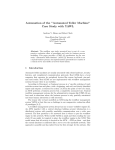
Joker: An Animator for Formal Languages
Diego Henrique Oliveira de Souza
Supervisor: Prof. PhD. Marcel Oliveira
Natal, RN, August 31, 2011
ii
iii
iv
To my mother Rozeli and my aunt
Lúcia, for the continuous help in the
academic and personal life.
v
Nothing great was ever achieved without enthusiasm.
Ralph Waldo Emerson -
vi
Acknowledgements
To God, for guiding and supporting me through entire life.
To my family, for the advices and help during this task.
To my supervisor, for the orientation.
To CAPES, for the financial help.
vii
viii
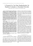
Abstract
Using formal methods, the developer can increase software’s trustiness and correctness. Furthermore, the developer can concentrate in the functional requirements of the
software. However, there are many resistance in adopting this software development
approach. The main reason is the scarcity of adequate, easy to use, and useful tools.
Developers typically write code and test it. These tests usually consist of executing the
program and checking its output against its requirements. This, however, is not always
an exhaustive discipline. On the other side, using formal methods one might be able
to investigate the system’s properties further. Unfortunately, specification languages do
not always have tools like animators or simulators, and sometimes there are no friendly
Graphical User Interfaces. On the other hand, specification languages usually have a compiler which normally generates a Labeled Transition System (LTS). This work proposes
an application that provides graphical animation for formal specifications using the LTS
as input. The application initially supports the languages B, CSP, and Z. However, using a
LTS in a specified XML format, it is possible to animate further languages. Additionally,
the tool provides traces visualization, the choices the user did, in a graphical tree. The
intention is to improve the comprehension of a specification by providing information
about errors and animating it, as the developers do for programming languages, such as
Java and C++.
Keywords: Graphical User Interface, Animation, Java, Formal Specifications, Formal
Methods.
ix
x
Resumo
Usando métodos formais, o desenvolvedor pode aumentar a confiabilidade e corretude do software. Além disso, o desenvolvedor pode concentrar-se mais nos requisitos
funcionais. Porém há muita resistência em se adotar essa abordagem de desenvolvimento
de software. A razão principal é a escassez de suporte ferramental adequado, útil e de fácil
utilização. Os desenvolvedores normalmente escrevem o código e o testam. Estes testes
geralmente consistem em checar se as saı́das estão de acordo com os requisitos. Isto, contudo, nem sempre é possı́vel de maneira exaustiva. Por outro lado, usando Métodos Formais um desenvolvedor é capaz de investigar profundamente as propriedades do sistema.
Infelizmente, linguagens de especificação formal nem sempre possuem ferramentas como
animador ou simulador e as vezes não há interfaces gráficas amigáveis. Porém, algumas
dessas ferramentas possuem um compilador, que gera um Sistema de Transições Rotuladas (LTS). A proposta deste trabalho é desenvolver um aplicativo que fornece animação
gráfica para especificações formais usando o LTS como entrada. O aplicativo inicialmente
suporta as as linguagens B, CSP e Z. Usando o LTS em um formato XML especificado
é possı́vel animar outras linguagens formais. Adicionalmente a ferramenta disponibiliza
visualização de traces, escolhas feitas pelo usuário, em um formato de árvore gráfica. A
intenção é melhorar a compreensão de uma especificação, fornecendo informações sobre erros e animando-a, como os desenvolvedores fazem com linguagens de programação
como Java e C++.
Palavras-chave: Interface Gráfica, Animação, Java, Especificação Formal, Métodos
Formais.
xi
xii
Contents
Contents
xiii
List of Figures
xvii
List of Tables
xix
List of Abbreviations
xxi
1
Introduction
1.1 Motivation . . . . . . . . . . . . . . . . . . . . . . . . . . . . . . . . . .
1.2 Objectives . . . . . . . . . . . . . . . . . . . . . . . . . . . . . . . . . .
1.3 Overview . . . . . . . . . . . . . . . . . . . . . . . . . . . . . . . . . .
2
Background
2.1 Formal Methods . . . . . .
2.2 Specification Languages .
2.2.1 CSP . . . . . . . .
2.2.2 B . . . . . . . . .
2.2.3 Z . . . . . . . . .
2.3 Labeled Transition Systems
3
.
.
.
.
.
.
.
.
.
.
.
.
.
.
.
.
.
.
.
.
.
.
.
.
.
.
.
.
.
.
.
.
.
.
.
.
.
.
.
.
.
.
Methodology
3.1 Strategy . . . . . . . . . . . . . . . . .
3.2 Research . . . . . . . . . . . . . . . . .
3.3 Related Work . . . . . . . . . . . . . .
3.3.1 Atelier-B . . . . . . . . . . . .
3.3.2 ProB . . . . . . . . . . . . . .
3.3.3 Rodin . . . . . . . . . . . . . .
3.3.4 Overture . . . . . . . . . . . .
3.3.5 Z/EVES . . . . . . . . . . . . .
3.3.6 ProBE . . . . . . . . . . . . . .
3.3.7 FDR2 . . . . . . . . . . . . . .
3.3.8 Perfect Developer . . . . . . . .
3.3.9 Alloy Analyzer 4.1 . . . . . . .
3.3.10 Key System . . . . . . . . . . .
3.3.11 Comparative Table . . . . . . .
3.3.12 Authors’ Previous Contributions
xiii
.
.
.
.
.
.
.
.
.
.
.
.
.
.
.
.
.
.
.
.
.
.
.
.
.
.
.
.
.
.
.
.
.
.
.
.
.
.
.
.
.
.
.
.
.
.
.
.
.
.
.
.
.
.
.
.
.
.
.
.
.
.
.
.
.
.
.
.
.
.
.
.
.
.
.
.
.
.
.
.
.
.
.
.
.
.
.
.
.
.
.
.
.
.
.
.
.
.
.
.
.
.
.
.
.
.
.
.
.
.
.
.
.
.
.
.
.
.
.
.
.
.
.
.
.
.
.
.
.
.
.
.
.
.
.
.
.
.
.
.
.
.
.
.
.
.
.
.
.
.
.
.
.
.
.
.
.
.
.
.
.
.
.
.
.
.
.
.
.
.
.
.
.
.
.
.
.
.
.
.
.
.
.
.
.
.
.
.
.
.
.
.
.
.
.
.
.
.
.
.
.
.
.
.
.
.
.
.
.
.
.
.
.
.
.
.
.
.
.
.
.
.
.
.
.
.
.
.
.
.
.
.
.
.
.
.
.
.
.
.
.
.
.
.
.
.
.
.
.
.
.
.
.
.
.
.
.
.
.
.
.
.
.
.
.
.
.
.
.
.
.
.
.
.
.
.
.
.
.
.
.
.
.
.
.
.
.
.
.
.
.
.
.
.
.
.
.
.
.
.
.
.
.
.
.
.
.
.
.
.
.
.
.
.
.
.
.
.
.
.
.
.
.
.
.
.
.
.
.
.
.
.
.
.
.
.
.
.
.
.
.
.
.
.
.
.
.
.
.
.
.
.
.
.
.
.
.
1
1
2
4
.
.
.
.
.
.
5
5
5
6
8
10
13
.
.
.
.
.
.
.
.
.
.
.
.
.
.
.
17
17
18
18
20
21
22
24
25
26
27
28
30
30
31
32
xiv
CONTENTS
3.4
4
5
3.3.13 Incorporating the Analysis Results . . . . . . . . . . . . . . . . .
Defining Work Boundaries . . . . . . . . . . . . . . . . . . . . . . . . .
Development
4.1 Joker . . . . . . . . . . . . . . . . . . . . . . . . .
4.2 Compilation . . . . . . . . . . . . . . . . . . . . .
4.2.1 CSP Compiler . . . . . . . . . . . . . . .
4.2.2 B Compiler . . . . . . . . . . . . . . . . .
4.2.3 Z Compiler . . . . . . . . . . . . . . . . .
4.3 LTS Readers . . . . . . . . . . . . . . . . . . . . .
4.3.1 CSP’s LTS Reader . . . . . . . . . . . . .
4.3.2 B’s LTS Reader . . . . . . . . . . . . . . .
4.3.3 Z’s LTS Reader . . . . . . . . . . . . . . .
4.4 Communicating with the Compilers . . . . . . . .
4.5 Integration of the LTS Readers into Joker’s Project
4.6 Translation of the LTS to Joker’s XML Format . .
4.7 XML Animation . . . . . . . . . . . . . . . . . .
4.8 Joker’s Main GUI . . . . . . . . . . . . . . . . . .
4.8.1 Animation Tab . . . . . . . . . . . . . . .
4.8.2 Specification Tab . . . . . . . . . . . . . .
4.8.3 LTS Tab . . . . . . . . . . . . . . . . . . .
4.8.4 XML Tab . . . . . . . . . . . . . . . . . .
4.8.5 LOG Tab . . . . . . . . . . . . . . . . . .
4.9 GUI Patterns Applied to Joker . . . . . . . . . . .
4.9.1 Safe Exploration . . . . . . . . . . . . . .
4.9.2 Instant Gratification . . . . . . . . . . . .
4.9.3 Satisfaction . . . . . . . . . . . . . . . . .
4.9.4 Changes in Midstream . . . . . . . . . . .
4.9.5 Deferred Choices . . . . . . . . . . . . . .
4.9.6 Incremental Construction . . . . . . . . . .
4.9.7 Habituation . . . . . . . . . . . . . . . . .
4.9.8 Spatial Memory . . . . . . . . . . . . . . .
4.9.9 Prospective Memory . . . . . . . . . . . .
4.9.10 Streamlined Repetition . . . . . . . . . . .
4.9.11 Keyboard Only . . . . . . . . . . . . . . .
4.10 Joker’s Web Site . . . . . . . . . . . . . . . . . . .
4.11 Joker Analysis . . . . . . . . . . . . . . . . . . . .
4.11.1 Joker Project Profile . . . . . . . . . . . .
4.11.2 Joker’s Project Data . . . . . . . . . . . .
4.11.3 Testing Joker . . . . . . . . . . . . . . . .
32
33
.
.
.
.
.
.
.
.
.
.
.
.
.
.
.
.
.
.
.
.
.
.
.
.
.
.
.
.
.
.
.
.
.
.
.
.
35
35
36
36
36
37
37
37
39
40
42
42
44
45
46
46
47
49
50
51
51
53
53
54
55
56
57
57
58
58
59
60
60
61
66
67
68
Case Studies
5.1 CSP Case Study - Airlock System . . . . . . . . . . . . . . . . . . . . .
5.2 B Case Study - Hotel Guests . . . . . . . . . . . . . . . . . . . . . . . .
5.3 Z Case Study - Process Scheduler . . . . . . . . . . . . . . . . . . . . .
71
71
74
76
.
.
.
.
.
.
.
.
.
.
.
.
.
.
.
.
.
.
.
.
.
.
.
.
.
.
.
.
.
.
.
.
.
.
.
.
.
.
.
.
.
.
.
.
.
.
.
.
.
.
.
.
.
.
.
.
.
.
.
.
.
.
.
.
.
.
.
.
.
.
.
.
.
.
.
.
.
.
.
.
.
.
.
.
.
.
.
.
.
.
.
.
.
.
.
.
.
.
.
.
.
.
.
.
.
.
.
.
.
.
.
.
.
.
.
.
.
.
.
.
.
.
.
.
.
.
.
.
.
.
.
.
.
.
.
.
.
.
.
.
.
.
.
.
.
.
.
.
.
.
.
.
.
.
.
.
.
.
.
.
.
.
.
.
.
.
.
.
.
.
.
.
.
.
.
.
.
.
.
.
.
.
.
.
.
.
.
.
.
.
.
.
.
.
.
.
.
.
.
.
.
.
.
.
.
.
.
.
.
.
.
.
.
.
.
.
.
.
.
.
.
.
.
.
.
.
.
.
.
.
.
.
.
.
.
.
.
.
.
.
.
.
.
.
.
.
.
.
.
.
.
.
.
.
.
.
.
.
.
.
.
.
.
.
.
.
.
.
.
.
.
.
.
.
.
.
.
.
.
.
.
.
.
.
.
.
.
.
.
.
.
.
.
.
.
.
.
.
.
.
.
.
.
.
.
.
.
.
.
.
.
.
.
.
.
.
.
.
.
.
.
.
.
.
.
.
.
.
.
.
.
.
.
.
.
.
.
.
.
.
.
.
.
.
.
.
.
.
.
.
.
.
.
.
.
.
.
.
.
.
.
.
.
.
.
.
.
.
.
.
.
.
.
.
.
.
.
.
.
.
.
.
.
.
.
.
.
.
.
.
.
.
.
.
.
.
CONTENTS
5.4
xv
Case Studies Analysis . . . . . . . . . . . . . . . . . . . . . . . . . . . .
78
Conclusion
6.1 Contribution . . . . . . . . . . . . . . . . . . . . . . . . . . . . . . . . .
81
81
A Examples
A.1 Student.csp . . . . . . . . . . . . . . . . . . . . . . . . . . . . . . . . .
A.2 Towns.mch . . . . . . . . . . . . . . . . . . . . . . . . . . . . . . . . .
A.3 Dining.tex . . . . . . . . . . . . . . . . . . . . . . . . . . . . . . . . . .
83
83
84
85
B Case Studies
B.1 Airlock.csp . . . . . . . . . . . . . . . . . . . . . . . . . . . . . . . . .
B.2 Hotelguests.mch . . . . . . . . . . . . . . . . . . . . . . . . . . . . . . .
B.3 Scheduler.tex . . . . . . . . . . . . . . . . . . . . . . . . . . . . . . . .
87
87
91
93
Bibliography
96
6
xvi
CONTENTS
List of Figures
2.1
2.2
2.3
2.4
Ticket Machine Execution on ProB . . . . . .
Machine Hotel Execution on ProB . . . . . .
IncubatorMonitor Execution on ProB . . . .
LTS for Ticket Machine’s MACHINE Process
.
.
.
.
.
.
.
.
.
.
.
.
.
.
.
.
.
.
.
.
.
.
.
.
.
.
.
.
.
.
.
.
.
.
.
.
.
.
.
.
7
11
14
15
3.1
3.2
3.3
3.4
3.5
3.6
3.7
3.8
3.9
3.10
Atelier-B Main Window . . . . . . . . . . . . . . . . .
ProB Main Window . . . . . . . . . . . . . . . . . . . .
Rodin Graphic Interface With ProB Plugin . . . . . . . .
Overture Graphic Interface Generating Proof Obligations
Z/EVES Main Window . . . . . . . . . . . . . . . . . .
CSP Animation on ProBE . . . . . . . . . . . . . . . .
FDR2 Main Window . . . . . . . . . . . . . . . . . . .
Perfect Developer Main Window . . . . . . . . . . . . .
Alloy 4 State Graphic Animation . . . . . . . . . . . . .
Key Main Window . . . . . . . . . . . . . . . . . . . .
.
.
.
.
.
.
.
.
.
.
.
.
.
.
.
.
.
.
.
.
.
.
.
.
.
.
.
.
.
.
.
.
.
.
.
.
.
.
.
.
.
.
.
.
.
.
.
.
.
.
.
.
.
.
.
.
.
.
.
.
.
.
.
.
.
.
.
.
.
.
.
.
.
.
.
.
.
.
.
.
.
.
.
.
.
.
.
.
.
.
21
22
23
25
26
27
28
29
30
31
4.1
4.2
4.3
4.4
4.5
4.6
4.7
4.8
4.9
4.10
4.11
4.12
4.13
4.14
4.15
4.16
4.17
4.18
4.19
4.20
Integration of the LTS Readers into Joker’s Project . . . . . . . . . . .
Joker’s Graphic Types . . . . . . . . . . . . . . . . . . . . . . . . . . .
Joker Main Window . . . . . . . . . . . . . . . . . . . . . . . . . . . .
Joker’s Animation Tab . . . . . . . . . . . . . . . . . . . . . . . . . .
Joker’s Specification Tab . . . . . . . . . . . . . . . . . . . . . . . . .
Joker’s Editor with Compilation Errors . . . . . . . . . . . . . . . . . .
Joker’s Editor Configuration . . . . . . . . . . . . . . . . . . . . . . .
Joker’s LTS Tab . . . . . . . . . . . . . . . . . . . . . . . . . . . . . .
Joker’s XML Tab . . . . . . . . . . . . . . . . . . . . . . . . . . . . .
Joker’s LOG Tab - Successful Compilation . . . . . . . . . . . . . . .
Joker’s LOG Tab - Specification with Errors . . . . . . . . . . . . . . .
Multi-Level Undo Pattern Applied in Joker’s Editor . . . . . . . . . . .
Automatic Compilation and Generation of the Animation by Joker . . .
Satisfaction Pattern over Joker’s GUI . . . . . . . . . . . . . . . . . . .
Wizard Pattern Applied to Options Window in Joker . . . . . . . . . .
Good Defaults Pattern Applied to Joker’s Font Family and Size . . . . .
Extras On Demand Pattern Applied To The Font Colors in Joker . . . .
Incremental Construction Pattern Applied To The Trace Viewer in Joker
Shortcut Patterns Applied to Joker . . . . . . . . . . . . . . . . . . . .
Responsive Disclosure Pattern Applied to Joker Objects . . . . . . . . .
.
.
.
.
.
.
.
.
.
.
.
.
.
.
.
.
.
.
.
.
43
45
46
47
48
49
50
51
52
53
54
54
54
55
55
56
56
57
58
59
xvii
.
.
.
.
.
.
.
.
.
.
.
.
.
.
.
.
.
.
.
.
xviii
LIST OF FIGURES
4.21
4.22
4.23
4.24
4.25
4.26
4.27
4.28
4.29
4.30
4.31
4.32
4.33
4.34
Movable Panels Pattern Applied to Joker Menus
Joker’s Animation with Loop . . . . . . . . . .
Joker’s Shortcut List . . . . . . . . . . . . . .
Joker Use Case Diagram . . . . . . . . . . . .
Joker Class Diagram . . . . . . . . . . . . . .
Joker Package Diagram . . . . . . . . . . . . .
Joker Component Diagram . . . . . . . . . . .
Joker Main Sequence Diagram . . . . . . . . .
Joker’s Transformation Sequence Diagram . . .
Joker’s Method Call Tree . . . . . . . . . . . .
Joker’s Package Call Tree . . . . . . . . . . . .
Joker’s Memory & Heap . . . . . . . . . . . .
Joker’s Threads . . . . . . . . . . . . . . . . .
Joker’s Threads Waiting . . . . . . . . . . . . .
.
.
.
.
.
.
.
.
.
.
.
.
.
.
.
.
.
.
.
.
.
.
.
.
.
.
.
.
.
.
.
.
.
.
.
.
.
.
.
.
.
.
.
.
.
.
.
.
.
.
.
.
.
.
.
.
.
.
.
.
.
.
.
.
.
.
.
.
.
.
.
.
.
.
.
.
.
.
.
.
.
.
.
.
.
.
.
.
.
.
.
.
.
.
.
.
.
.
.
.
.
.
.
.
.
.
.
.
.
.
.
.
.
.
.
.
.
.
.
.
.
.
.
.
.
.
.
.
.
.
.
.
.
.
.
.
.
.
.
.
.
.
.
.
.
.
.
.
.
.
.
.
.
.
.
.
.
.
.
.
.
.
.
.
.
.
.
.
.
.
.
.
.
.
.
.
.
.
.
.
.
.
.
.
.
.
.
.
.
.
.
.
.
.
.
.
59
60
61
62
63
64
64
65
65
66
67
67
68
68
5.1
5.2
5.3
5.4
5.5
5.6
5.7
5.8
5.9
Airlock System Scheme . . . . . . . . . . . . . . . . . . . . .
Airlock System Possible States . . . . . . . . . . . . . . . . .
Airlock System Possible Animations for AIRLOCK Process .
Airlock System Possible Animations for AIRLOCK2 Process .
Hotelguests First Possible Options . . . . . . . . . . . . . . .
Hotelguests Possible Options With Occupied Rooms . . . . .
Scheduler Processes State Transitions . . . . . . . . . . . . .
Process Scheduler Animation Through Joker’s Graphic - Part 1
Process Scheduler Animation Through Joker’s Graphic - Part 2
.
.
.
.
.
.
.
.
.
.
.
.
.
.
.
.
.
.
.
.
.
.
.
.
.
.
.
.
.
.
.
.
.
.
.
.
.
.
.
.
.
.
.
.
.
.
.
.
.
.
.
.
.
.
73
73
74
75
75
76
77
78
78
List of Tables
2.1
2.2
Machine Readable AMN . . . . . . . . . . . . . . . . . . . . . . . . . .
Temperatures Suitable for Newborn Babies . . . . . . . . . . . . . . . .
12
12
3.1
Formal Method Tools - Comparative Table . . . . . . . . . . . . . . . . .
32
4.1
4.2
Joker1.0 Main Data . . . . . . . . . . . . . . . . . . . . . . . . . . . . .
Tested Specifications and Errors Found . . . . . . . . . . . . . . . . . . .
69
69
xix
xx
LIST OF TABLES
List of Abbreviations
ACM - Association for Computing Machinery
AMN - Abstract Machine Notation
API - Application Programming Interface
AST - Abstract Syntax Tree
CADP - CAESAR/ALDEBARAN Development Package
CRefine - Circus Refinement
CSP - Communicating Sequential Processes
CSP-M - Machine Readable CSP
CZT - Community Z Tools
EPL - Eclipse Public License
FDR - Failures-Divergence Refinement
GUI - Graphic User Interface
IDE - Integrated Graphics Environment
IMG - Image
I/O - Input/Output
IKIWISI - I Will Know It When I See It
JAR - Java Archive
JDK - Java Development Kit
JML - Java Modeling Language
JVM - Java Virtual Machine
JRE - Java Runtime Environment
xxi
xxii
JUNG - Java Universal Network/Graph Framework
LAF - Look And Feel
LOTOS - Language of Temporal Ordering Specifications
LPTS - Labeled Predicate Transition System
LTS - Labeled Transition System
MSN - Microsoft Service Network
NASA - National Aeronautics and Space Administration
NSF - National Science Foundation
ProBE - Process Behavior Explorer
RSS - Rich Site Summary
SLR - Systematic Literature Review
SWEBOK - Software Engineering Body of Knowledge
TCL - Tool Command Language
UML - Unified Modeling Language
VDM - Vienna Development Method
WYSIWYG - What You See Is What You Get
LIST OF TABLES
Chapter 1
Introduction
This chapter presents the motivation of this work. Furthermore, it lists the objectives
of this dissertation and describes the operational mechanism of our work.
1.1
Motivation
Software engineering is a discipline that is concerned with all software development
aspects. To plan and develop a new software, engineers make use of software processes,
which are sets of activities and results that generate the final product [56].
Formal methods is a software development approach that aims at guaranteeing the
software correctness despite its inherent complexity [11]. Using formal specifications,
the software engineers can concentrate their efforts in what really matters, that is, what
the software is supposed to do. This characteristic allows the engineers to postpone some
activities without interfering in the development schedule [3].
The formal specification of a system uses languages such as B [52], Circus [43],
CSP [27], LOTOS [6], Z [60], and many others. Some of these languages, like CSP,
focus on the specification of concurrent systems. Others, such as Z and B, concentrate on
the specification of sequential systems. Finally, we have some notations that combine the
specification of the concurrent and sequential aspects of a system, such as Full LOTOS
and Circus [3, 43].
The necessity of formal methods is accepted in the research community [9]. In [9],
Michael Holloway discusses reasons to use formal methods: “software engineers make
an effort to be real engineers, who traditionally use appropriate mathematics. Hence,
given that formal methods is the mathematics of computing, software engineers should
use appropriate formal methods”. Nevertheless, resistance in adopting this development
methodology is usual. Why is there so much resistance in adopting this development
methodology [53]?
In the 80’s, the tool support for formal methods was inadequate and too difficult to use
[11, 7]. How changed is the situation nowadays? Do the current tools supply the needs
of developers who use formal methods nowadays? We present below the opinion of some
researchers in the area.
• Michael Holloway: “Suggested causes include lack of adequate tools...” [9].
1
2
CHAPTER 1. INTRODUCTION
• Dines Bjørner: “I believe that progress in use of formal methods will only come
provided three conditions are met: (1) production of enough candidates from computer science departments oriented towards programming methodology–too many
have learned about theories of no use in programming; (2) employment of such
people in critical mass groups; and (3) appropriate tools.” [3].
• Jonathan Bowen and Mike Hinchey: “In the future, we expect more emphasis to be
placed on integrated formal development support environments, which are intended
to support most formal-development stages, from initial functional specifications
through design specifications and refinement. There environments will also support
specification animation...” [7].
• Betty H. C. Cheng and Joanne M. Atlee: “Verification techniques can be used to
prove that the software specification meets these requirements. Research in this
area focuses on improving the information provided to the stakeholder for feedback,
including animations...” [10].
• Edmund M. Clarke and Jeannette M. Wing: “The use of tools for formal methods
should be integrated with that of tools for traditional software development, for
example, compilers and simulators”, “...formal methods can help customers nail
down their system requirements more precisely” and “...make our notations and
tools accessible to non experts” as part of the article Formal Methods: State of the
Art and Future Directions [11].
• Barry Boehm: “Formal methods had difficulties with scalability and usability by
the majority of less expert programmers...” and “Developing software is not a “what
you see is what you get” methodology, it is “I’ll know it when I see it”. Because
of that, testing and animating is essential for debugging and fixing problems” [5].
By providing appropriate tools, with specification, animation and visualizations, the
formal methods community will make it easier for developers to incorporate these methods in the development process increasing its acceptance rate. The work presented in this
dissertation provides a Java framework, which can be used to animate specifications written in formal languages, such as CSP, Z or B. The framework does not aim at compilation
nor verification. These functions remain in the original tools. Our framework takes the
LTS of a specification and animates it using graphical components, such as buttons, panels and frames. The library allows the user to view the trace and the tree of possible next
steps the user might take throughout the system’s execution.
1.2
Objectives
Our main objective is to develop a tool that is capable of animating formal specifications of any language and which can be reused for other tools. Our tool, Joker, is currently
able to animate B, CSP, and Z. For that, it includes existing compilers for each of these
formal language as project dependencies. The specifications are compiled using these
compilers and the generated Labeled Transition System (LTS) containing a finite number
of states is then animated by Joker. The idea is to give to the user a visual animation, that
1.2. OBJECTIVES
3
yields a better understanding of the specification. Additionally, errors identified by the
compilers are highlighted in the Joker’s editor.
Despite Joker just animates LTS with a finite number of states, the user can use it for
teaching or interaction with clients, as explained in the next paragraphs. Furthermore, the
LTS can contain loops and the user can animate the same specification infinitely. Joker
can be easily adapted for animating specifications with a infinite number of states in their
LTS by using on-the-fly animation. This is explained in section 6.1.
It is important to remark that our original idea was to develop an animator for Circus and it could not be done because the language’s compiler was out of date. Then
we decided to develop a generic animator that could be adapted to animate Circus with
a minimum effort. Circus is formed by CSP and Z. Because of that, we have choose
these languages as initial supported languages for Joker. ProB is the compiler we use to
generate the LTS for Z. We have observed that the LTS generated for B and Z are similar. The amount of work necessary for animating B was minimum, around ten hours of
programming, then we decided to animate B too.
Joker can be customized and extended for further languages: the user needs to provide
the specification’s LTS in the specified XML format. Joker reads this LTS and provides
the animation, including the trace and outputs. For that, Joker uses the XML module
that we have developed. It is capable of generating a XML file for the compilers outputs,
i.e. the LTS. Using the same reasoning, Joker can receive this same XML format but for
other languages. The XML module, containing the XML file generation and the XML
file reader, is part of the contribution of this work.
It is distributed as a compacted file that contains: Joker itself as a .jar executable file,
the dependencies (compilers and Java libraries), and examples for each language. Joker
is implemented in Java. Hence, it is portable and can be executed on Linux, Mac OS
X, and Windows. However, its dependencies, the compilers, are platform dependent and
because of that Joker is distributed in two different packages, one for Windows and other
for Linux/Mac. It is a lightweight application that does not use too much computational
resources.
The tool can be used for teaching purposes, supporting the teacher in class by providing graphical animation for the specifications that are being explained. I can be used by
the students to examine the language details by changing specification and analyzing its
behaviour when animated.
Another possible use of this tool is to interact with the client in the requirements
elicitation process. Most of the times, the client does not know exactly what he wants
from the system. By animating the specification and showing it to the client, the software
engineers can identify errors of specification or understanding.
The types of systems that could use Joker depends on the used language. If a formal
specification language is adequate for hardware, and Joker can animate it, so the tool is
useful for understanding that hardware specified in that language which is being animated
by Joker. The correct reasoning is to understand that this tool animates the LTS with a
finite number of states, if the specification has an infinite number of states, so this tool is
inadequate for this specification, whatever language it is.
Joker does not intend to be the “silver bullet”. There are animators for formal methods.
4
CHAPTER 1. INTRODUCTION
The difference is that Joker is a generic animator that can contribute to the development of
other tools such as IDEs for other languages. These IDEs can use Joker as the animator,
so the developers can use the time that would be spent developing the animator in other
kind of tools for their language.
1.3
Overview
Chapter 2 gives to the reader the necessary information for a better understanding
about this work’s contents. The reader who is familiar with formal methods, B, CSP, and
Z may skip this chapter. In chapter 3, all the research process is explained in details.
This chapter is important for readers that are interested in reusing our work [53]. In the
sequence, chapter 4 is related to the development process of the tool. All the programming issues are discussed in this chapter, including technologies, tools, frameworks and
libraries that were used along this work. Chapter 5 presents three case studies: the first
one is an animation of a CSP specification, the second one is an animation for Z, and the
third one an animation for B. Concluding this dissertation, Chapter 6 discusses the main
contributions of this dissertation, related work, and future work.
Chapter 2
Background
The objective of this chapter is to provide a background to the reader within this
work. A brief explanation of Formal Methods is given at Section 2.1. In Section 2.2,
three specification languages are described using simple examples.
2.1
Formal Methods
Formal methods is an approach to software development. It is composed of mathematically based languages called specification languages, techniques, and tools for specifying and verifying systems. The use of formal methods does not guarantee the software
correctness. However they can increase the understanding of a system by revealing inconsistencies, ambiguities, and incompleteness that might otherwise go undetected [11].
Another great advantage of formal methods is that it allows the developer to focus the
development attention on what to do, and after that on how to perform the functions [3].
The use of formal methods, in the past, seemed hopeless because of the obscure notations and difficulty to use tools [11]. However, nowadays the use of formal methods is
being more used in software engineering. The mathematical basis is different from that
of civil engineering, but it has the same purpose: to add precision, to aid understanding,
and to reason about design properties [60].
2.2
Specification Languages
Specification is the process of describing a system and its desired properties. A formal
specification uses a language with a mathematically defined syntax and semantics. The
kinds of system properties may include functional behavior, timing behavior, performance
characteristics, or internal structure. So far, specification has been most successful for behavioral properties. One current trend is to integrate different specification languages,
each being able to handle different aspects of a system. Another is to handle non behavioral aspects of a system such as its performance, realtime constraints, security policies,
and architectural design [11].
Some formal methods such as Z [60] and VDM [4] focus on specifying the behavior of sequential systems. States are described in terms of rich mathematical structures
5
6
CHAPTER 2. BACKGROUND
such as sets, relations, and functions. State transitions are given in terms of pre and
post-conditions. Other methods, such as CSP [27], focus on specifying the behavior of
concurrent systems. States typically range over simple domains like integers or are left
uninterpreted, and behavior is defined in terms of sequences, trees, or partial orders of
events. Others combine two different methods, one for handling rich state spaces and one
for handling complexity due to concurrency, such as Circus [11].
The three languages supported by Joker, CSP, B, and Z, are described in more details
below.
2.2.1
CSP
CSP (Communicating Sequential Processes) was designed for describing systems of
interacting components. In CSP, processes are considered independent entities and selfcontained. These processes have interfaces which allow them to interact with the environment in which they are inserted. A process can only interact with other processes through
its interface. The interface’s behaviour contains important information about the process.
The process’ interface can be described by a set of events. An event describes an atomic
action that can be performed by the process. The first issue in describing a process is
to decide the set of events that the process can perform. This set of events provides the
description of the process. Based on this set of events, users of CSP are able to describe
the desired behavior of the system [51].
We introduce CSP using a simple example of a ticket machine system. This specification starts with the channel declaration, where all the channels used in the specification
are declared:
channel dollar_1000, ticket, miami, paris, turnon, turnoff
Then, the process MACHINE, that allows the user to turn on the machine and then select
a destination to travel.
MACHINE = turnon -> TICKET
The main process for this specification is SYSTEM, that puts a client, process CLIENT,
in parallel with the process MACHINE. The ALPHA defines an alphabet that will be used to
communicate the SYSTEM and CLIENT processes.
ALPHA = {| turnon, turnoff, miami, paris, dollar_1000, ticket |}
SYSTEM = MACHINE [| ALPHA |] CLIENT
CLIENT = turnon -> paris -> dollar_1000 -> dollar_1000 ->
ticket -> turnoff -> CLIENT
When this specification is executed, the initial provided channel is turnon. After that,
the specification will provide three choices, represented by the operator ([]) inside the
process TICKET:
2.2. SPECIFICATION LANGUAGES
7
TICKET =
(miami -> dollar_1000 -> ticket -> TICKET)
[]
(paris -> dollar_1000 -> dollar_1000 -> ticket -> TICKET)
[]
(turnoff -> MACHINE)
These choices provided by TICKET process are: miami, paris, and turnoff. By
choosing the miami destination, the user can select the miami channel, then the specification will request the payment of dollar_1000, deliver the ticket and finally turnoff
the ticket machine. If the user chooses the paris destination, the specification will provide paris channel, then request dollar_1000 twice, deliver the ticket, and finally
turnoff the ticket machine. The last option, turnoff, just turnoff the ticket machine
in case of withdrawal of purchasing the ticket.
Executing SYSTEM as main process, the only possible choice is paris because CLIENT
is running in parallel with SYSTEM and this channel is the unique synchronization possible.
The previous paragraph explains the entire TICKET process for describing the possible
choices when this process is the main one executed.
An execution of this specification using SYSTEM as main process using ProB can be
seen in Figure 2.1. ProB is a multi-language tool for formal methods. It is described in
details in subsection 3.3.2.
Figure 2.1: Ticket Machine Execution on ProB
In this figure, the Ticket machine was executed as can be seen in History box, from
8
CHAPTER 2. BACKGROUND
the bottom to the top: the machine was turnon, then paris was selected, dollar_1000
was paid twice, then the ticket was received.
2.2.2
B
B is a structured method that uses the concept of abstract machines to specify systems
or system’s parts. It is compositional and hierarchical, meaning that one machine may be
defined in terms of other machines.
A machine describes what the system can do. It might receive inputs, provide outputs,
and perform changes to the system’s state. The machine is divided in the following sections: MACHINE, VARIABLES, INITIALISATION, OPERATIONS, INVARIANT, CONSTANTS,
SETS, PROPERTIES, CONSTRAINTS, INCLUDE, SEES, and USES.
The machine’s name is declared in section MACHINE. The machine’s state is defined
in terms of variables that are declared in the VARIABLES section. The initial state of
the machine is described in the section INITIALISATION. The machine operations are
declared in the OPERATIONS section. The operations may change the state’s variable or
not. The section INVARIANT describes the machine’s invariant, that is, conditions that
must be satisfied throughout the machine’s execution and to avoid unallowed states. The
INITIALISATION and the operations should not violate the INVARIANT. New types can
be introduced in the machine through the SETS section. The CONSTANTS section lists
all the constants that will be used in the machine. The PROPERTIES section describes
the conditions that must be maintained throughout the execution of the machine. The
information about restrictions in the machine parameters are in the CONSTRAINTS section.
The difference between the INVARIANT and CONSTRAINTS sections, is that the second one
is concerned with the parameters only. One machine may INCLUDE others and see their
variables. One machine can also SEES or USES other machines. The difference between
these two last structuring mechanisms is that in SEES the top machine can not relate its
state with the state of the machine in the SEES section, and in the USES section it can relate
the states of the top machine and the machine being used.
For example, the machine Hotel from [52] specifies a system that tracks the number
of guests in the hotel’s rooms. All the symbols used in this specification are explained in
Table 2.1. This machine SEES the machines below:
MACHINE
CONSTANTS
PROPERTIES
END
MACHINE
SETS
END
Size
sze
sze : NAT1
Rooms
ROOM
The definition of the machine Hotel start as follows:
MACHINE
Hotel
2.2. SPECIFICATION LANGUAGES
9
The section SEES in Hotel just defines that it can see the variables in the machines
Size and Rooms.
SEES
Rooms, Size
The constant sze defines the number of rooms in the hotel, i.e., it represents the cardinality of the set ROOM. The quantity of guests in the hotel is tracked by the variable
numbers. Each room can be of one of two types: the room for 4, or for 6 people. The
smaller rooms are members of the set small.
CONSTANTS
PROPERTIES
VARIABLES
INVARIANT
small
card(ROOM) = sze & small <: ROOM
numbers
numbers : ROOM --> 0..6 & numbers[small] <: 0..4
The Hotel INITIALISATION just starts all the ROOM with the value zero.
INITIALISATION
numbers := ROOM * {0}
There are six operations in the Hotel machine. There is an operation checkin(rr,nn)
which accepts a number of a room and a number of guests as input. The precondition for
this operation is that the room is not occupied and the number of guests fits in that room.
OPERATIONS
checkin(rr,nn) =
PRE rr : ROOM & nn : 1..6 & numbers(rr) = 0 & (rr : small => nn <= 4)
THEN numbers(rr) := nn
END;
The operation checkoout(rr) receives a room number as input, and resets to zero its
number of guests.
checkout(rr) =
PRE rr : ROOM
THEN numbers(rr) := 0
END;
The operation nn <-- roomquery(rr) receives a room number and return the number
of occupants for that room. Its precondition is that the room number rr belongs to the set
ROOM.
nn <-- roomquery(rr) =
PRE rr : ROOM
THEN nn := numbers(rr)
END;
10
CHAPTER 2. BACKGROUND
The operation nn <-- vacancies outputs the number of unoccupied rooms.
nn <-- vacancies = nn := card(numbers |> {0});
The operation totalguests outputs the total number of guests in the hotel.
nn <-- totalguests = nn := SIGMA ( zz ) . (zz : ROOM | numbers(zz));
The last operation, swap(rr,ss), puts the occupants of the room rr in the room ss. Its
precondition requests that the rooms rr and ss belongs to the set ROOM and these rooms
must have the same size.
swap(rr,ss) =
PRE rr : ROOM & ss : ROOM & ((rr : small) <=> (ss : small))
THEN numbers := numbers <+ {rr |-> numbers(ss),ss|-> numbers(rr)}
END
END
There are some tools for B, such as ProB, Atelier-B and Rodin. These three tools are
analyzed in Section 3.3. The MACHINE Hotel can be seen being executed on ProB in
Figure 2.2.
In Figure 2.2, the machine Hotel was just opened, and this is the initialization phase,
when the constants are being set.
2.2.3
Z
Z is a notation formed by the combination of mathematical logic and set theory. The
mathematical logic is a first-order predicate calculus. In the set theory are included the
standard set operators, set comprehension, cartesian products, and power sets. In Z,
mathematical objects can be arranged together in schemas: patterns of declaration and
constraints. The system state, the ways this state can change, the system properties and
possible refinements of a design are also described using the schema notation. In Z, every object has an unique type, which allows type-checking programs to verify it in the
specification. Refinement is also supported by Z. The refinement can be repeated until
executable code is generated [60]. The description of time behavior, concurrent behavior,
non-functional properties such as security, usability and performance are not Z’s focus
[60].
A Z example is the IncubatorMonitor adapted from Jim Woodcock’s Z notation
classes slides for this brief explanation [59]. This system is responsible for maintaining
an environment temperature between a minimum and a maximum value. For this example
let’s consider a neonatal incubator, that is responsible for maintaining the baby’s temperature controlled. The minimum value for a baby with 3kg is 28o C, and the maximum
is 30o C, according to Table 2.2 adapted from [46]. The increment and decrement operations are responsible for changing the temperature’s value. The operation getTemp
2.2. SPECIFICATION LANGUAGES
11
Figure 2.2: Machine Hotel Execution on ProB
returns the current temperature in the incubator. The operation IncubatorMonitor verifies if the temperature is in the safe range. Finally, the operation IncubatorMonitor Init
initializes the temperature with the value 29o C.
The constants block below defines MIN as 28 and MIN as 30. These values will be
used to control the temperature, defined as temp.
MIN == 28
MAX == 30
The schema below defines the IncubatorMonitor. Its precondition defines that temp
belongs to the set Z and it is in the range from MIN to MAX, already defined above as
28 and 30, respectively.
IncubatorMonitor
temp : Z
MIN ≤ temp ≤ MAX
The ∆ indicates that the operation Increment may change the IncubatorMonitor’s
State increasing the value of temp by one. The precondition for executing this operation,
is that temp must be less than MAX.
12
CHAPTER 2. BACKGROUND
Machine Readable AMN
Symbol
Meaning
:
Belongs to
NAT1
Positive Numbers
card()
Cardinality
<:
Subset
&
And
-->
Total Function
..
Range
*
Cartesian Product
:=
Assignment
=>
Greater than or equal to
<=
Less than or equal to
<-Operation declaration
|>
Range Restriction
.
General Product
<=>
If and only if
<+
Relational Override
|->
Maps to
Table 2.1: Machine Readable AMN
Temperature Range for Newborn Babies
Weight (in Kg) Temperature Range (in o C)
1.0 - 1.5
34 - 35
1.5 - 2.0
32 - 34
2.0 - 2.5
30 - 32
2.5 - 3.0
28 - 30
Table 2.2: Temperatures Suitable for Newborn Babies
Increment
∆IncubatorMonitor
temp < MAX
temp0 = temp + 1
Again, the Delta operator indicates that the operation Decrement may change the
IncubatorMonitor’s State decreasing the value of temp by one. The precondition for this
operation, is that temp must be greater than MIN.
2.3. LABELED TRANSITION SYSTEMS
13
Decrement
∆IncubatorMonitor
temp > MIN
temp0 = temp − 1
The symbol ! below, indicates that currentTemp is an output that will provide the
value of temp.
GetTemp
ΞIncubatorMonitor; currentTemp! : Z
currentTemp! = temp
The constant block below defines the initTemp with the value 29.
initTemp == 29
The schema below just starts the value of temp with the value of initTemp.
IncubatorMonitor Init
IncubatorMonitor0
temp0 = initTemp
Z/EVEs and ProB are examples of tools that supports Z. These tools are analyzed in
Section 3.3. The IncubatorMonitor can be seen being executed on ProB in Figure 2.3.
In Figure 2.3 the IncubatorMonitor is being executed on ProB. As can be seen in
the History Box, the first executed action was the INITIALISATION, that is IncubatorMonitor Init which sets the value of temp as 29. Then the operation GetTemp is
executed, returning the value of temp, 29. The operation Increment is executed once,
then the operation GetTemp is executed again, returning 30. In the sequence, the operation Decrement is executed, then the operation GetTemp is called again, to verify the
value of temp, that is 29. The operation Decrement is called again, then the GetTemp
operation returns 28. Finally, the operation Increment is executed as the last one. In
the EnabledOperations Box, is possible to see that if the operation GetTemp is called the
value returned will be 29 again.
2.3
Labeled Transition Systems
This section briefly explains what is a Labeled Transition Systems (LTS) for readers
that are not familiarized with formal methods. A LTS is a set of states and transitions
between those states. A state is a node and a transition is an arch. The transition is labeled
with the action that has changed the previous state to the next one. It means that this arch
14
CHAPTER 2. BACKGROUND
Figure 2.3: IncubatorMonitor Execution on ProB
is directed. The LTS has an initial state but not always the end state, because it can be
infinite. Formally, an LTS is a tuple:
(S, A, → S0)
where:
1. S is a (finite) set of states
2. A is a set of actions
3. A transition relation is
→⊆ S ∗ A ∗ S
4. The initial state is
S0 ∈ S
For example, the Ticket machine’s LTS for MACHINE process, from subsection 2.2.1,
is textually represented below:
2.3. LABELED TRANSITION SYSTEMS
15
(0,turnon,1)
(7,ticket,1)
(1,miami,2)
(1,paris,4)
(1,turnoff,5)
(6,dollar_1000,7)
(2,dollar_1000,3)
(3,ticket,1)
(4,dollar_1000,6)
(5,turnon,1)
The information is separated by commas. The first information represents the key of
the node. The second information represents the arch that can be followed to the next
node. The last information is the key of the next node. For this example, the initial node
is represented by the key 0 (zero). A graphical version of this LTS is provided below for
a better analysis:
Figure 2.4: LTS for Ticket Machine’s MACHINE Process
Starting from the node 0, it is possible to turnon the ticket machine. Then the execution goes to node 1. From node 1, it is possible to turnoff the machine, select
miami or paris to travel. When miami is selected, the execution goes to node 2, then
dollar_1000 can be executed, then the execution goes to node 3, the user can get the
ticket and the execution returns to node 1. If the user select paris, the execution goes
to node 4, then dollar_1000 can be executed, reaching node 6, then dollar_1000 can
be executed again, reaching the node 7, and the user can select ticket, and the execution
goes to node 1 again. If the user select turnoff, the execution goes to node 5, then the
user can turnon the machine, starting the whole process again.
This chapter introduced the readers to the basic concepts of Formal Methods, Specification Languages, B, CSP, Z and LTS. These concepts are essential for understanding the
next chapters and the tool we have developed. The next chapter explains the methodology
that we have utilized to develop this work.
16
CHAPTER 2. BACKGROUND
Chapter 3
Methodology
This Chapter describes the agenda to do this entire work and the research done intending to develop Joker as a modern tool in the context of formal methods. In addition, ten
other tools are analyzed and their good qualities are provided inside Joker.
3.1
Strategy
This work was developed in parallel, whenever possible, to save time. Other activities that depended of third parties, such as the compilers, were scheduled in such a way
that any undesirable delay would not compromise the entire agenda. A research in 104
software engineering articles was done before any programming. Another research in 10
Formal Method tools was done. The objective was to develop a modern tool, that is in
accordance with the Formal Methods tools.
To start Joker’s development, all the required software was installed, such as Java
SDK and NetBeans IDE. Joker’s main GUI prototype was developed. In it, all the events
and functions were added on demand. After defining Joker’s acceptable input, i.e. the
LTS, the LTS readers were developed for B, CSP, and Z. Joker does not compile these
languages, it just animates the already compiled specification, the LTS. To compile the
specifications, Joker uses third parties compilers: CSPM Tool (for CSP) and ProB (for B
and Z).
After developing Joker’s main GUI and the LTS readers, all the functionalities were
integrated and automatized. As a result of our effort in automating the overall process,
no manual work is required from the user. All the communication with the compilers,
error handling, and any other animation steps are controlled by Joker. To test all this
automation, three Case Studies were developed, one for each language: B, CSP, and Z.
Additionally, 140 specifications were tested in the tool. The results were evaluated and
some changes were done in the main GUI and animation mechanism. After that, the tool
was prepared for distribution, compacted with all the dependencies, and put in Joker’s
project web site 1 for download, together with the help material: video and javadoc.
1 http://code.google.com/p/jokeranimator
17
18
CHAPTER 3. METHODOLOGY
3.2
Research
The initial task of this work was a study on software engineering, more specifically
in software engineering and formal method tools papers, documentation, tutorials, books
and manuals. This task provided us with information about the state of the art in formal
method tools and to observe the problems that have been bothering the developers since
the 80’s.
This study followed the instructions about Systematic Literature Review (SLR) in
[8]. The use of SLR [30] helps the student to obtain an objective summary of research
evidence relative to a subject [29]. Besides that, it helps to gather a background material
and to identify a possible conflict between the work and another one. The work quality
is also improved. Because of these motives, this procedure was adopted as the first task
of this work [8]. The SLR was done in more than one hundred documents. It had a great
contribution to our work since it provided us a background on formal methods tools that
allowed us to chose specific characteristics that are desirable in such tools [8].
The “algorithm” followed to do this SLR was:
1.
2.
3.
4.
3.3
Selection of documents by title and abstract;
After further analysis, some of them were discarded (35);
Some documents could not be acquired for reading (20);
The remaining amount of documents were summarized (50).
Related Work
Before developing Joker, ten tools were analyzed: ProBE [49], FDR2 [49], Rodin
[37], Overture IDE [33], Alloy Analyzer [55], Perfect Developer [14], Key System [14],
ProB [35], Z/EVES [50], and Atelier-B [48]. The characteristics evaluated for each tool
were: sub tools availability, installation, documentation, license, portability, graphic user
interface, limitations on the theorem prover, automation, language support, efficiency,
community, and technical support.
Among the sub tools considered there are: text editor, model checker, type checker,
theorem prover, animation, code generation and other utilities such as integration with
UML or possibility of exporting the code to LATEX. To evaluate the editor, some examples
were changed to verify if the editor helps the developer to locate errors and fix them. The
animation was analyzed by the execution of the examples and its changes. The model
checker and type checker were analyzed in the same way. Other utilities were analyzed
according to its nature. For example code generation, in which the execution of the code
was verified and compared against the specification. Additionally, the generated code was
analyzed.
Installation Process The installation process is very different for each tool. Some of
them do not need to be installed, like the Java based tools, and others need a complex
procedure, like CADP, which was discarded of the analysis because it was not possible to
3.3. RELATED WORK
19
install it successfully. Some tools like ProB have dependencies, like TCL8.4 dll libraries
or Z/EVES, which needs Python 1.5.2.
Documentation The tool documentation consists in manuals, tutorials, guides, examples, source code, videos and code documentation. Each tool provides a different kind of
documentation. Some provide just the tool manual, like FDR2, and others, like Alloy4,
provide videos that teach how to use the animator and the editor.
License Type The licence is an important characteristic to be evaluated. We can split
the tools into two categories: paid and free. Some tools provide a free and a commercial
version. Usually, the commercial version has more features than the free one. In this
experience, most free tools presented limitations, execution problems and no support.
Portability The Operating System (OS) portability consists in checking if the tool is
available for different OS such as Linux, Mac OS, Solaris, Windows, and others. The
java based tools, like Rodin, Overture, Alloy4 and Key, can run in any OS with the JRE
installed. Other tools like FDR2, can run exclusively in Linux. Perfect Developer can run
in Linux and Windows, but its editors are just for Windows.
Graphic user Interface (GUI) The Graphic User Interface (GUI) is an important characteristic, since it has a direct impact in the tool usability. In the past, interaction with
the tools was mostly through command lines. However, since the 80’s, this interaction
has considerably changed, but not as much as expected. Some of them are inefficient and
have limitation to deal with the state explosion problem [11]. Furthermore, some tools
still have no specification editor, like ProBE. The absence of this feature slows down the
process of debugging the specification and tracking important changes.
Limitations The limitations are a tricky characteristic to be analyzed. Tools like ProB
openly describe their limitations on their web site, but most tools try to show only their
benefits. Some examples were run in each tool to verify if it could edit, animate, prove or
generate code without problems. Additionally, an e-mail was sent to each tool company
asking for further information about its limitations.
Efficiency The efficiency was analyzed based on the time needed by the tool to do a
specific task, the generated code quality, the utility of the sub tools such as the editor or
proof obligation generator and other characteristics, like the use of memory, CPU time
and commands to do the task.
Automation The automation consists in the tool’s capability to generate results automatically, like counterexamples, proof obligations, valid instances, and code.
20
CHAPTER 3. METHODOLOGY
Language Support The language support refers to the languages that the tool accepts,
as input and output. For instance, ProB accepts Z, CSP and B as input. Perfect Developer
accepts specifications in Perfect and generates, with some limitations, output in C, C#2.0
or Java.
Community The analysis of the tools’ communities refers to the integration with other
users, developers and maintainers of the tool. Some tools do not provide any community,
like FDR2 and ProBE, and others provide a very active community, like Overture, that has
MSN meetings, workshops, mailing list, contact by the site and many projects running.
Support The technical support is given by the community or the software owner. Usually, the commercial license provides the support, as in the cases of Perfect Developer and
Atelier-B. Some tools do not provide even an e-mail to contact the software maintainer,
as in the case of Z/EVES.
In what follows we describe each of the tools we analyzed with respect to these characteristics.
3.3.1
Atelier-B
Atelier-B (Figure 3.1) is a tool for specifying and developing software using the BMethod. This tool was developed by ClearSY System Engineering 2 and is freely available. There is one specific installation file for every different OS. A commercial version
is also available and provides updates and efficient support. Some advances in formal
methods introduced by B are: pre and post conditions, guarded commands, stepwise refinement, a refinement calculus, and data refinement. Abstract Machine Notation (AMN)
provides a common framework for the construction of specifications, refinements, and implementations which can be formally verified [52]. Atelier-B provides a graphic interface
which integrates an editor, a theorem prover and a code generation tool. It offers specification refinement and automatic generation of proof obligations. There is an option to
install the ProB animator plugin to improve the animation. The specification editor helps
to develop the code by completing it and underlining errors and by highlighting reserved
words, comments and names. The tool can type check and perform the B0 check, which
consists of checking if the specification can be automatically translated into code. When
a refinement is proposed by the user, the tool can automatically verify its correctness.
Atelier-B can also generate a dependency graph and export the source code to PDF, RTF
and LATEX. Atelier-B can refine automatically or interactively. Proof obligations may be
automatically proved. In cases where this is not possible, an interactive prover can be
used within Atelier-B.
The tool usability is reasonable and the errors are indicated in the text editor, not
always in a clear manner. The syntax is different from that used by the B-Toolkit [52]
and no examples were found to verify the differences. Furthermore, some symbols may
lead to proof failure, such as closure, generalized intersection and union. However these
2 www.clearsy.com
3.3. RELATED WORK
21
Figure 3.1: Atelier-B Main Window
limitations can be overcome by the introduction of user mathematical rules. These points
can discourage new users to adopt this tool. The tool is being used industrially by Alstom
Train Systems and Siemens. The tool’s web site 3 provides manuals, tutorials, source
files, and industrial applications’ articles.
3.3.2
ProB
ProB was the easiest and most useful animator analyzed. It can be used for B, CSP and
Z language. It has one installation file per OS (Windows, Mac OS, and Linux) which can
be downloaded from the ProB web site 4 . However, the tool has a dependency to TCL8.4.
Originally, ProB is a model checker for the B language, with some limitations. However,
nowadays, it also supports CSP and Z, with some limitations 5 . During animation, ProB
shows in the editor the part of the specification that is being animated. This helps to
identify and locate errors and to better understand the code. The ProB main window with
the text editor in the center and animator in the bottom can be seen in Figure 3.2. ProB has
a user manual, some tutorials, and some examples from [52]. Its web site provides a bug
report utility, tutorials, a developer manual, a recent changes log, and some useful links
like a wiki. There is a plugin for Atelier-B to use the ProB animator, and also for Rodin.
3 www.atelier-b.eu
4 www.stups.uni-duesseldorf.de/ProB/
5 http://www.stups.uni-duesseldorf.de/ProB/index.php5/Current
Limitations
22
CHAPTER 3. METHODOLOGY
Figure 3.2: ProB Main Window
This tool is implemented in SICStus Prolog and aims to cover all B4Free, which is a set of
tools for the development of B models, and Atelier-B constructs. Some goals intended for
ProB are multiple machines refinement and state space visualization. The Atelier-B tree
operations are not supported, and there are some restrictions on the DEFINITION clause.
All the limitations are listed in the tool’s limitations page 6 . When editing a specification
in B, for example, the tool indicates the errors just when the machine is model checked.
The line numbers are not shown and the error messages are not always clear. To use the
graphical tools, such as the state space graphical view, the user needs to perform a further
configuration and to install a third party software, dotty.
3.3.3
Rodin
The use of commonly used Integrated Development Environments (IDE) like NetBeans and Eclipse as a tool platform can bring many benefits to the tool’s users. These
IDEs have editors, testing tools like JUnit, graphic interface drawing tools, UML tool integration and many other tools. Some formal method tools already have used such IDEs
as their platform. For example, there are the Eclipse based tools Rodin for Event-B and
Overture for VDM dialects.
Rodin does not need installation. It can be used just by unzipping the files in the
OS file system. It is available for all the OS under Eclipse Public License (EPL). As
6 http://www.stups.uni-duesseldorf.de/ProB/index.php5/Current
Limitations
3.3. RELATED WORK
23
Figure 3.3: Rodin Graphic Interface With ProB Plugin
an Eclipse extension it is itself extensible: many plugins can be downloaded, using the
Eclipse Plugin Manager, according to the user needs, like AnimB 7 , B2Rodin 8 , which
allows users to import into the Rodin platform textual B models, developed with AtelierB, the B animator Brama 9 , ProB and Atelier-B provers. This analysis was done on
Rodin version 1.3 with AnimB, ProB and Atelier-B provers plugins. The tool proved
to be easy to use. This IDE is full of features, like the possibility of using Atelier-B
provers, an editor editor with syntax highlighting, a theorem prover, and an automatic
proof obligations generator. The theorem prover is fully automatic, but it is completely
configurable. The Rodin main window with the editor in the middle, ProB plugin in the
right, project explorer in the left, and operations opened in the lower left corner can be
seen in Figure 3.3. To create an Abstract Machine (AM), Rodin provides many wizards.
7 http://animb.org/index.xml
8 http://www.bmethod.com/php/outils-b-plugin-b2rodin-en.php
9 http://www.bmethod.com/php/outils-b-plugin-brama-en.php
24
CHAPTER 3. METHODOLOGY
Even to create a variable a window is opened, asking for its initialization and properties
in the invariant. Eventually, the user can edit all the AM fields directly. When editing
the code, some icons appear indicating that some variables were not initialized yet or the
initialization is not a refinement. There is a box with all the symbols used to write an
AM. It is very useful, because if the symbols are not supported, the user must use ASCII,
like described in [52]. Animation can be done using the ProB or AnimB 10 plugins. The
former being more efficient and easy to use. The support is given by the web site 11 with
Frequent Asked Questions (FAQ), industrial examples (with the corresponding article and
source code), and community. The site provides e-mails to contact the developers and a
mailing list. In the present experience, both were responsive. The documentation consists
of language manual, developer manual, user manual, tutorials, and two book chapters.
3.3.4
Overture
Another Eclipse based tool is Overture IDE. It is a development environment for
VDM dialects (VDM-SL, VDM-PP and VDM-RT). It is available for free under EPL and
can be downloaded from the tool’s web site 12 . The version analyzed here is the 0.2. The
Vienna Development Method (VDM) is one of the longest established model-oriented
formal methods for the development of computer-based systems and software [4]. VDM
models can be expressed in a specification language (VDM-SL) which supports the description of data and functionality [15]. This tool consists in three parts: the Kernel, the
IDE and the Plugins. The Kernel, called VDMJ, consists of a parser, an abstract syntax
tree, a type checker, an interpreter with test coverage features and proof obligation generator. Overture IDE is built on top of the Eclipse Platform, like Rodin. All the files loaded
by VDMJ are parsed and type checked automatically. If a specification does not parse
and type check correctly, the interpreter cannot be started and proof obligations cannot be
generated. The tool focus in the automatic generation of proof obligations. Like Rodin,
it has many features: text editor, animator, theorem prover, UML tool, LATEX generator,
pretty printing, debugger, and type checker. The editor is different from Rodin’s, it allows
to edit the code directly, without filling windows’ forms. Overture’s debugger allows to
insert breakpoints in the code to verify possible errors. The Overture’s main window with
the proof obligations generated in the lower part, text editor in the middle, and project
explorer in the left can be seen in Figure 3.4. It provides technical support by e-mail,
but in this work experience there were no answers. The web site also provides manuals,
a user guide and some examples. Compared with the other tools, this one has the most
complete community: MSN talks, workshops, mailing list and many projects using the
tool. The workshops happens twice in a year, but the mailing list is not so active. A feature that drew attention was the animator. It allows the choice between a single or double
Computer Processing Unit (CPU) representation.
10 http://animb.org/index.xml
11 www.event-b.org/platform.html
12 www.overturetool.org
3.3. RELATED WORK
25
Figure 3.4: Overture Graphic Interface Generating Proof Obligations
3.3.5
Z/EVES
Z/EVES provides a good visualization and edition of Z specifications. It can be used
for parsing, type checking, domain checking, schema expansion, precondition calculation,
refinement proofs, and proving theorems. Its inputs are Z/LATEX source files, which is a
LATEX markup, compatible with Z. The Z notation is based on the set theory and first order
predicate calculus. Mathematical objects and their properties can be arranged in schemas.
The schema language can be used to describe the state of a system and its properties,
allowing reasoning about refinement [60]. Z/EVES is available for free in different web
sites 13 . It has a back-engine prover with a few user interfaces. There is a visual one for
Python, a textual one in emacs, and a semi-visual one for Eclipse. Z/EVES has specific
commands and uses Z/LATEX markup, but the user does not need to know that to use the
tool graphically. The theorem prover is semiautomatic and needs interaction of the user
in most occasions. This tool has a good editor that indicates the lines with errors, and it
is easy to use. Unfortunately it does not provide animation. There is no community or
13 http://www.uni-koblenz.de/winter/Lehre/SS01/ZEves/ZEves.html#dokumentation
26
CHAPTER 3. METHODOLOGY
support site on the web. There is a user manual for the version 2.0. This tool project is
currently discontinued. The Z/EVES main window with schemes [60] opened in it can be
seen in Figure 3.5.
Figure 3.5: Z/EVES Main Window
3.3.6
ProBE
Using tools like ProBE (Process Behaviour Explorer) the developer can animate a
given specification. In the case of ProBE, the specification is written in CSP [51]. Using
ProBE the user is able to choose the next state in the animation based on all possible
paths shown by the tool. ProBE uses a hierarchical list to display the possible actions and
states of a process, as can be seen in Figure 3.6. There is an option to see the animation
execution trace. This feature helps to identify and locate errors in the specification. ProBE
implements the operational semantics described in [49]. It can be downloaded at the
Formal Systems web site 14 . The version analyzed for this work was 1.3. It comes with
14 www.fsel.com
3.3. RELATED WORK
27
Figure 3.6: CSP Animation on ProBE
the user manual, but no examples or any support. ProBE does not require installation and
is available for Windows, Linux, FreeBSD and Solaris. It does not have an editor, and it
has no automation, no code completion or fixes. It simply animates a correct specification.
This tool does not help to correct the code. When some error is found, the error message
given is “Parser error near line ...”, however, it does not describe the error. Furthermore,
more than one error may occur in the same location. For a CSP student it is very hard to
identify the error, specially because the line number sometimes is wrong. To develop a
complete and verified CSP specification, the developer must use another tool in addition
to this one, like FDR2, which is a model checker for state machines based on Roscoe’s
CSP [27].
3.3.7
FDR2
FDR (Failure-Divergence Refinement) is a model checker for CSP which can verify the specification and its refinements [49]. Three types of refinements can be verified: traces, failures and failures-divergences. The version analyzed here is the 2.83 which
is available for free at Formal Systems web site 15 for academic use only. A commercial
license grants support and allows commercial exploration. The tool can verify whether
the process can reach a state in which no further action is possible, a deadlock. Livelock
and determinism can also be checked with FDR. These three checks can be seen in Figure
15 www.fsel.com
28
CHAPTER 3. METHODOLOGY
3.7. There is an experimental option to generate a graph of the selected processes which
allows to rearrange the states. The interface is Motif Linux based. So, there are versions
Figure 3.7: FDR2 Main Window
for Linux, Solaris and Mac OS, but no Microsoft Windows’ versions. It is split in tabs
for refinement, deadlock, livelock, determinism, and evaluation. The tool has a debugger
which helps to find errors by providing counter examples to the assertions. The documentation is limited to the program manual, which describe the installation process, the basic
features and the improvements between all the FDR versions.
3.3.8
Perfect Developer
Perfect Developer is a commercial tool developed by Escher Technologies. There are
two license types: commercial and evaluation. The tool is available for Linux and Windows OS, and the editors, Crimsom and TexPad, are just for Windows. Perfect Developer
uses its own language named Perfect. This work analyzed the evaluation version of the
tool, which can be used academically or to develop open source software. The logic used
is a many-sorted first-order predicate calculus, extended to support function and operator
preconditions, inheritance and dynamic binding [28, 47]. The prover is fully automatic,
3.3. RELATED WORK
29
and non-interactive. For real software development projects, Perfect Developer usually
gets 98% to 100% success in automatic proof of verification conditions if the program
does not use data refinement, and better than 95% if it does. This tool can generate executable code in Java, C++, and C#2.0 automatically. The code generated is verified to
ensure that it implements the specification adequately. It also has a type checker and a
UML tool. The graphic interface is simple and the code needs to be opened in another
program separately to be edited. The support is given by tutorials, language reference
manual, hints, examples and user guide. The technical support is granted for those paying
the commercial licence, like Atelier-B. However, previous experiences [12] have shown
us that support for academic licenses was also very responsive: many questions about the
use of Perfect Developer, were answered in a few hours. Regarding limitations, Perfect
Developer is designed for single-threaded applications only. With care, it can be used
to develop multi-threaded systems, but it does not verify concurrency properties. The
Perfect Developer main window can be seen in Figure 3.8.
Figure 3.8: Perfect Developer Main Window
30
3.3.9
CHAPTER 3. METHODOLOGY
Alloy Analyzer 4.1
The Alloy Analyzer 4.1 is an editor and animator for Alloy. It is freely available as
a .jar file which can be executed in any OS with a JRE. Alloy notation is inspired in Z
(sets, relations, and uniformity) and SMV (rapid, not declarative and counterexamples,
not proofs). This tool has its own editor, but the user can edit the code using Eclipse,
VIM or Emacs, by installing the provided support plugins. The graphical interface is
based on Java Swing and the animator is very interesting and configurable. It shows
many shapes and lines representing the states and the possible choices (see Figure 3.9).
It allows to choose a theme and form of the animation. It does an automatic analysis of
the code, generating counter-examples in approximately 50 milliseconds, depending on
the model size. Technical support is available via e-mail. In this experience, however, it
Figure 3.9: Alloy 4 State Graphic Animation
was not responsive. Besides e-mail, Alloy Analyzer’s developers also provide RSS news,
publications, tutorials, and videos. The community is maintained by the Massachusetts
Institute of Technology (MIT).
3.3.10
Key System
The Key System is a tool for verification of Object-Oriented Software in Java Modeling Language (JML). It has versions for Java, Java Card, Hoare Calculus [26], C and
Java multi-threaded programs. This tool has a Java Swing GUI which integrates the theorem prover and other sub tools. It can simplify expressions and generate proof obligations, which can be automatically verified. Furthermore, this tool has a proof obligations
checker, a model checker, a type checker, and a theorem prover. There is a Key System
plugin for Eclipse. The site www.key-project.org/ is very complete. It provides many
versions for free download, the developer’s contacts, many publications in PDF format,
links with materials and courses, case studies, tutorials, and a mailing list. Some e-mail
addresses are provided, but are not responsive. The Key System main window can be seen
in Figure 3.10.
3.3. RELATED WORK
31
Figure 3.10: Key Main Window
3.3.11
Comparative Table
Table 3.1 shows all the main data collected in this work. Some words are abbreviated
for the sake of conciseness: Editor (ED), Animation (AN), Automation (AT), Theorem
Prover (TP), Model Checker (MC), Installation Process (IP), Error Fixes (EF), Proof Obligations (PO), Code Fix (CF), Find Valid Instances (FVI), Theorem Prover (TP), Java Web
Start (JWS), Code Generation (CG), License (LIC), Documentation (DOC), Language
Support (LS), Community (CM), Support (SP), Limitations (LT), Linux (L), Windows
(W), Characteristic (CH), and Eclipse Based GUI(Eclipse).
As can be seen in Table 3.3.11, the current formal method tools are not complete.
Some are specialized in animation, like ProB and Alloy Analyzer, and others in the generation of proof obligations, like Overture and Rodin. The choice of the tool will depend
on the software development needs, budget, chronogram, and the software type. To develop software using B-Method, the recommended tool identified is Atelier-B with ProB
plugin for animation. Atelier-B is a good tool, which allows abstraction refinement and
implementation. It can also generate code in C. For specifying systems in CSP, the tools
that can be used are FDR2 and ProBE. ProBE can be used in the first steps, to verify if
the specification is in conformance with the user needs. Alternatively, ProB can also be
used to animate CSP specifications. After that, the refinement can be written and verified
in FDR2. Livelock, deadlock, and determinism can also be checked in FDR2. Using the
Z notation, Z/EVES can be used for editing the code, and ProB for its animation. For
32
CH./Tool
ED
TP
PO
CG
AN
MC
IP
DOC
LIC
PT
GUI
LT
EF
AT
LS
CM
SP
CHAPTER 3. METHODOLOGY
ProBE
Rodin
No
No
No
No
Yes
No
No
No
Free
L and W
Window
AN
Good
None
CSP
No
No
Yes
Yes
Yes
Yes
Yes
Yes
Unzip
Yes
Free
All OS
Eclipse
AT
Good
PO
Event B
Yes
Free
Formal Method Tools - Comparative Table
Overture
Alloy
Perf. D.
ProB
Z/EVES
Yes
Yes
Yes
Yes
Yes
Yes
Unzip
Yes
Free
All OS
Eclipse
AN
Good
PO
VDM
Yes
Free
Yes
Yes
Yes
No
Yes
Yes
No
Yes
Free
Full
Java
AT
Great
FVI
Alloy
Yes
Free
No
Yes
No
Yes
No
Yes
Wizard
Yes
Paid
L and W
Window
AT
Average
CG
Perfect
No
Paid
Yes
No
No
No
Yes
Yes
Wizard
Yes
Free
All OS
Frames
CF
Great
Checks
B, Z, CSP
No
No
Yes
No
No
No
No
Yes
Wizard
Yes
Free
L and W
Window
TP
Average
Checks
Z
No
No
Atelier-B
Key S.
FDR2
Yes
Yes
Yes
Yes
No
Yes
Wizard
Yes
Paid
All OS
Frames
TP
Good
PO
B
No
Paid
No
Yes
Yes
No
No
Yes
JWS
Yes
Free
All OS
Java
TP
Good
None
JML
No
No
Yes
Yes
No
No
No
Yes
Unzip
Yes
Paid
Linux
Tabs
AN
Good
EF
CSP
No
Paid
Table 3.1: Formal Method Tools - Comparative Table
generating code automatically, Perfect Developer is the most indicated tool because it
provides three languages as output and the code generation is fully automatic. The other
tools can be used according to the selected language: Alloy Analyzer for Alloy, Key for
JML, Overture for VDM, and Rodin for Event-B.
3.3.12
Authors’ Previous Contributions
In previous work [41] an IDE was developed for LOTOS. It contains editor, animator,
code fixer, error finder, deadlock finder, livelock finder and many other tools organized
in a Java Swing GUI. The program, called JLotos, was entirely developed in Java, using
NetBeans IDE 6.5 on Ubuntu Linux 8, and can be executed in every OS freely, just by
running a single .jar file, without installation process or dependencies. The tool has its
limitations: it supports only Basic LOTOS, not Full LOTOS [6]. In the Full LOTOS, value
associations to gate’s names are allowed. This permission allows an infinite number of
variations. The Basic LOTOS just describes the processes synchronization, while the Full
LOTOS do that and describes the communication of values between them. Other JLotos
limitations includes: the compiler is not formalized, the code fix is not fully automatic,
and it has no support, just the Javadoc, some tutorials and a demonstrating video. JLotos
is being updated in [2] to support Full LOTOS. In another previous work [42] a tactic
language for refinement, called ArcAngel, was developed. Additionally, the tool support
was also developed.
3.3.13
Incorporating the Analysis Results
A tool that integrates several utilities, simple to use, with a useful editor, with automatic verifications, code generator, friendly GUI, and useful features is very difficult to
find.
3.4. DEFINING WORK BOUNDARIES
33
After analyzing ten tools, it is clear that some have just one good tool, like the animator
(Alloy Analyzer), some do not provide support, like Z/EVES, and just two, Rodin and
Overture, have a good interface which integrates various tools, like a professional IDE for
formal software development.
From ProB, we incorporated the simplicity of the GUI and the editor’s text highlighting. From Overture and Rodin, Joker inherited the principles of portability, no installation
process and IDE structure. The generation of graphical trees was inspired by the Alloy
Analyzer. Furthermore, Joker is freely distributed because it was developed using Java
with free software, such as NetBeans. Joker is portable, but its dependencies are not.
Because of that, Joker has a package for Linux/Mac and another one for Windows.
Developers want tools that make their work easier. This is true both for academia and
for industry. Tools with theorem provers that are difficult to use, like Z/EVES and the
Atelier-B for example, are in practice not very attractive.
3.4
Defining Work Boundaries
The initial idea was to develop an animator for Circus. Unfortunately, the Circus’
Model Checker [17] was outdated and unsynchronized with the CZT [38]. Due to time
restrictions, our initial proposal was slightly changed: we focused on the creation of a
generic animator for formal languages that uses the specification’s LTS as input. It is an
ambitious task, because there are many specification languages. But the idea is to develop
an animator that initially supports CSP and Z. Additionally, this animator must be able
to receive a XML file which contains the LTS of a specification in other language, and
animate it.
This animator is called Joker and it is composed by a window with many components
such as buttons, panels, and graphics. The main components in the GUI are the Animation Tab, Interaction Viewer, Trace Viewer, Output Viewer, Specification Tab, LTS Tab,
XML Tab, and LOG Tab. Other components do not appear graphically, but they perform
important tasks in background, such as the LTS Readers and the Initialization System. All
the Joker’s details are explained in the next Chapter.
34
CHAPTER 3. METHODOLOGY
Chapter 4
Development
This chapter explains technical issues that were raised throughout the development
of Joker: project details, dependencies, technologies, patterns, softwares, strategies, and
computational resources are analyzed in detail. The details range from the acquisition of
the LTS generators up to details of the distribution package composition.
4.1
Joker
Joker is an application that was developed to animate formal languages. The animation can help the user to understand the specification behavior and locate errors. Additionally to the animation, Joker also provides a full colored and customizable editor, that
helps the user to understand the language syntax and locate errors that are shown painted
in red. Other several functionalities are provided, such as a LOG Viewer containing all
the information about the communication with the compilers, the compilation itself, LTS
generation, XML translation, animation, and file handling.
This tool intends to animate any formal language by receiving its LTS as input. This
LTS must be in the specified XML format to be read and work properly. To demonstrate
its functionalities, Joker already comes prepared to animate B, CSP, and Z. Joker does not
compile the specifications, but takes compiled specifications and animates them. It sends
the specifications to the compilers included in Joker’s distribution package. CSP’s compilations are achieved using Marc Fontaine’s CSPM Tool [36], and B and Z compilation is
achieved using ProB’s compilers [35]. Joker’s mechanism is not simple. Several steps are
needed to complete this task. All these steps are hidden from the user, but he has access
to these information via the LOG Viewer. The main steps for the user are:
1. Open the specification for B, CSP, Z or XML for other languages
2. Click in ANIMATE or press F6
3. Click in the buttons that the animation provides (Animation direct on the Graphics
is also possible)
However, in the background, many further steps are needed. In summary, the steps
for an animation are:
1. Verify the language used in the specification
35
36
CHAPTER 4. DEVELOPMENT
2. Interact with the corresponding compiler in order to get either a successful compilation resulting in a LTS or an error message.
3. Translate the LTS to Joker’s XML format
4. Animate the XML
Joker was developed using an adaptation of the Extreme Programming (XP) method.
Several functionalities were developed per week and validated in a weekly meeting, where
other functionalities and changes were requested. The pair programming was not applied,
but the code was revised several times, and the necessary refactoring were done. The main
artifacts produced were the UML diagrams and the code itself. The meetings produced
minutes to be followed and some forms were filled by students which tested the tool.
4.2
Compilation
As previously stated, Joker is an animator for formal languages. It is not concerned
with the compilation process and type-checking. Instead, it reuses compilers that are
already available in academia, which can generate the LTS given as input to Joker’s animation.
Formal Systems Europe, FDR and ProBE developer, was the first contact. Unfortunately, they were unresponsive and further contacts were needed.
The two next contacts were successful and contributed to the success of this work.
First, ProB team provided compilers for B and Z specifications. Next, Marc Fountain’S
CSPM contributed with a compiler for CSP specifications.
4.2.1
CSP Compiler
The very first practical experience was with CSPM , which proved to be very intuitive.
The integration was achieved in a relatively trivial manner. Our integration and case
studies demonstrate small problems that were quickly solved by the tool’s provider. The
LTS generated is very complete and does not depend on additional steps. This LTS is
a little complex because each node can contain operators, such as choice and internal
choice.
ProB can compile and generate the LTS for CSP, but it is not as organized as the
CSPM’s LTS. Furthermore, two different tools must be used to prove that Joker is generic
and can interact with other tools.
The successful compilation of CSPM generated a file containing the LTS. In Section
4.3.1 we describe how Joker treats this LTS in order to achieve animation. CSPM Tool
generates a file in the same folder that contains the LTS.
4.2.2
B Compiler
The ProB’s B compiler generates, in a single step, the LTS. The state information is
not provided in this LTS, but a Java API is currently being developed by ProB team to
4.3. LTS READERS
37
solve this problem. As a direct consequence of this current ProB’s limitation, Joker currently does not provide state information for B and Z animation. Furthermore, animation
on-the-fly is also not currently possible. This restricts animation to finite specifications.
However, it is already compatible and able to provide state information if available in
the animation’s input, a XML file described in Section 4.6. After successful compilation
ProB generates a file in the same folder that contains the LTS.
4.2.3
Z Compiler
ProB’s Z compiler generates the LTS for Z in the same format as the LTS for B. Nevertheless, the procedure is slightly different. The generation of the LTS for a Z specification
is achieved in two steps:
1. Generation of a .fuzz file that contains a compiled Z specification in Lisp format
2. Compilation of the lisp specification into ProB’s LTS format
A successful compilation in these cases generate a .pl file that contains the LTS generated. Again, this file is given as input to the specific LTS reader. These readers converge
the different LTS format into a common XML format file that is used by Joker to animate
the specification. In the next section, the LTS readers are described.
4.3
LTS Readers
This section explains in details how the LTS readers were developed. Additionally, a
example of compilation and application of the LTS reader is presented for each accepted
language.
4.3.1
CSP’s LTS Reader
Marc Fontaine’s CSPM-Interpreter package can generate LTS from CSP specifications. The procedure was already explained in Subsection 4.2.1. This LTS however must
be read and converted into a format that makes sense to Joker.
To explain all the transformation process, we use a little specification. The specification MutualRecursion.csp was compiled with CSPM Tool. The specification and the
generated LTS having START as main process are shown below:
channel coin, chocolate
START = coin -> PAID
PAID = chocolate -> START
In this specification, the compiler calls START as main process. This process calls
the action coin and then the process PAID. This last process calls the action chocolate,
then calls START again, recommencing the cycle.
38
CHAPTER 4. DEVELOPMENT
GPINIT = GP_HashMD5_C6BB729C588A90F8BC3E9DE420B2B777
GP_HashMD5_C6BB729C588A90F8BC3E9DE420B2B777 =
(coin -> GP_HashMD5_F4BE29BCCEB53276A79903A2EEA931C0)
GP_HashMD5_F4BE29BCCEB53276A79903A2EEA931C0 =
(chocolate -> GP_HashMD5_C6BB729C588A90F8BC3E9DE420B2B777)
In the LTS the nodes are represented by a pair of key-content. The key GPINIT is the
very first node to be read. It contains just the key of the first node of the LTS. Following the
sequence, the content of the node with the initial key indicates that after the execution of
coin the key invoked is GP HashMD5 F4BE29BCCEB53276A79903A2EEA931C0.
The node with this key has as content that indicates that after the execution of chocolate,
the node invoked is the one with the initial key, closing the cycle of the mutual recursion.
This is just a simple example for a better understanding, but bigger specifications can
contain choices and internal choices in the nodes. Other operators do not appears in the
nodes. These nodes must be prepared for Joker before animation. The preparation of this
LTS was one of the most difficult tasks in this work.
The very first algorithm for this task is the node separation. The entire LTS is just a
text saved in a file, nothing is prepared yet. The nodes starts with a key, but they can have
multiple lines. All the nodes’ contents are inside parenthesis. An algorithm that separates
the contents reads since the node’s “=” symbol, which divides the key from the content,
until it finds the very last closing parenthesis “)” for that node.
After the node separation, the content must be separated too. It can be divided in many
other nodes, according to the operators in it. For example, if a content has a single choice
operator, it will be transformed in two different nodes, but with the same key.
The class that does all this preparation is CSPNodes which contains 336 lines of code.
This class uses another class called CSPNode, which represents a simple node, with a key,
an event, and a next node.
The class CSPNodes verifies all the nodes of the generated LTS and converts them to
a CSPNode object. For MutualRecursion.csp, the nodes according to Joker’s LOG are:
NODE******************************
KEY:
root
EVENT: root
NEXT: GP_HashMD5_C6BB729C588A90F8BC3E9DE420B2B777
NODE******************************
KEY:
GP_HashMD5_F4BE29BCCEB53276A79903A2EEA931C0
EVENT: chocolate
NEXT: GP_HashMD5_C6BB729C588A90F8BC3E9DE420B2B777
NODE******************************
KEY:
GP_HashMD5_C6BB729C588A90F8BC3E9DE420B2B777
EVENT: coin
NEXT: GP_HashMD5_F4BE29BCCEB53276A79903A2EEA931C0
4.3. LTS READERS
39
For this example, the class CSPNodes has separated the nodes contents in the symbol
->. The same reasoning is done when a choice operator ([]) is found. The difference is that
in the choice operator, all the options must have the same key. This is necessary because
Joker shows to the user all the options that are offered for that key.
Initially, a basic CSP’s LTS animator was developed as a project separated from Joker.
After that, the basic animator was integrated with the Joker’s main window, as will be
explained in section 4.5.
4.3.2
B’s LTS Reader
ProB can generate LTS for B specifications, as explained in Subsection 4.2.2. Having
received the LTS it is necessary to read it. Additionally, it must be converted to a format
which Joker can understand.
The specification Doors below will help through the explanation of the transformation
process. The LTS, which is in text format, must be transformed into node objects, which
Joker can read. In this specification, the door can be open or closed, according to the set
POSITION. There are two operations: opening and closedoor. These two operations
just opens the door and closes it, respectively.
MACHINE
Doors
SETS
DOOR; POSITION = {open, closed}
VARIABLES
position
INVARIANT
position : DOOR --> POSITION
INITIALISATION
position := DOOR * {closed}
OPERATIONS
opening(dd) =
PRE dd : DOOR & position(dd) = closed THEN position(dd) := open END;
closedoor(dd) =
PRE dd : DOOR & position(dd) = open THEN position(dd) := closed END
END
The generated LTS for this specification is partially shown below:
spec_trans(root,’$initialise_machine’,0).
spec_trans(0,’opening(DOOR1)’,1).
spec_trans(0,’opening(DOOR2)’,2).
spec_trans(0,’closedoor(DOOR1)’,0).
spec_trans(0,’closedoor(DOOR2)’,0).
...
In this LTS, each line starting with spec trans is a node. Each node has a key, an
event, and a next node. The initial nodes have the key “0”. These information are separated by a comma “,”. After separating the nodes, and the nodes’ information, the objects
must be mounted. The class that executes all this process is ZBNodes.
40
CHAPTER 4. DEVELOPMENT
The ZBNode object has a key, an event, and a next key. When some node is executed,
the next node is called, using the next key indicated in that node. The node separation for
Doors is partially shown below:
NODE******************************
KEY =
0
EVENT = opening(DOOR1)
NEXT = 1
NODE******************************
KEY =
0
EVENT = opening(DOOR2)
NEXT = 2
...
A basic B’s LTS animator was developed as a separated project. Later, this B basic
animator was integrated into the Joker’s main window, as will be explained in section 4.5.
4.3.3
Z’s LTS Reader
ProB can also generate LTS for Z specifications, as explained in subsection 4.2.2.
After obtaining the LTS, it must be read and separated in objects that make sense to Joker.
The specification Simple below will be used to show how the Z transformation process
is done.
[TEST]
The Schema State just defines that the state belongs to the TEST set related to itself.
State
state : TEST ↔ TEST
The Schema Init initializes the state with the value , i.e. empty
Init
State0
state0 = {}
The two following Schemas, Inc and Invert, changes the values of state by mapping
its values or inverting it.
4.3. LTS READERS
41
Inc
∆State
pos? : TEST
value? : TEST
#state ≤ 1
state0 = state ⊕ {pos? 7→ value?}
Invert
∆State
state0 = state∼
The generated LTS for Simple is:
spec_trans(root,’$initialise_machine’,0).
spec_trans(0,’Inc(TEST1,TEST1)’,1).
spec_trans(0,’Inc(TEST1,TEST2)’,2).
spec_trans(0,’Inc(TEST2,TEST1)’,3).
spec_trans(0,’Inc(TEST2,TEST2)’,4).
spec_trans(0,’Invert’,0).
spec_trans(1,’Inc(TEST1,TEST1)’,1).
spec_trans(1,’Inc(TEST1,TEST2)’,2).
spec_trans(1,’Inc(TEST2,TEST1)’,5).
spec_trans(1,’Inc(TEST2,TEST2)’,6).
...
As can be seen, this LTS is like the previous one for B. The used classes are also the
same: ZBNodes and ZBNode. The separation process is the same, the only difference
between B and Z is the previous step, which is the LTS generation itself, as explained in
section 4.2. The node separation for Simple is partially shown below:
NODE******************************
KEY =
0
EVENT = Inc(TEST1,TEST1)
NEXT = 1
NODE******************************
KEY =
0
EVENT = Inc(TEST1,TEST2)
NEXT = 2
NODE******************************
KEY =
0
42
CHAPTER 4. DEVELOPMENT
EVENT = Inc(TEST2,TEST1)
NEXT = 3
...
A basic Z’s LTS animator was developed as a new project separated of Joker’s project.
In other step this Z basic animator was integrated to Joker’s main window, as will be
explained in section 4.5.
4.4
Communicating with the Compilers
The LTS readers for CSP, B, and Z were developed in separated projects. Joker was
also another separated project. Furthermore, the specifications were being compiled manually and them read by the LTS readers. Joker intends to be fully automatic. Because of
that, the communication with the compilers must be done hidden from the user. Additionally, the LTS readers must be integrated to Joker’s main window. The communication
with the compilers is explained in this subsection, and the integration of the LTS readers
is explained in section 4.5.
To use Java to communicate with executable files with “.exe” extension on Windows
or using the ./ over Linux it is necessary to access the environment. This is done using
Java Runtime class 1 .
These commands are mounted according to the specification that is being compiled
and the folder that Joker is in. Joker automatically configures itself when executed, identifying the folder that it is in and changing the commands. It also change the commands to
generate the LTS and the XML in the same folder that the specification being compiled.
The messages returned by the compiler are very important. Because of that, Joker
gets all the messages and shown them in the LOG Tab. The information messages and
the error messages are shown in the LOG. An example showing the editor with errors is
shown in Figure 4.6 and the corresponding LOG is shown in Figure 4.11.
4.5
Integration of the LTS Readers into Joker’s Project
The LTS readers were developed separately from Joker’s project, as described in section 4.3. But Joker intends to be fully automatic, which means that no further steps can
be added to the user in the animation process.
All LTS readers were included into Joker’s project, as can be seen in Figure 4.1. This
inclusion avoided code repetition, like the package io and the classes ZNodes.java and
ZNode.java.
The very first CSP animator had 218 LOC, distributed over 3 classes and the Z Animator had 185 LOC, also distributed in 3 classes. Neither of them had a graphical interface
and each of them read already compiled LTS in different formats. Hence, the introduction
1 http://download.oracle.com/javase/6/docs/api/java/lang/Runtime.html
4.5. INTEGRATION OF THE LTS READERS INTO JOKER’S PROJECT
43
of a GUI would, most likely, require duplicated coding effort. The integration required
some changes in the code for a better software engineering and patterns usage. For example, instead of animating three different LTSs, Joker just animates the XML, that is
generated from the LTS for each language. The process of generating this XML is explained in section 4.6.
With the conclusion of this step, Joker can already animate B, CSP, and Z from the
main window, without opening any other program. The communication with the compilers is automatic, and the LTS readers are already included in the project. But for a
homogeneous animation for all the three languages, there is one step more: the generation of the XML containing the information about the generated LTS.
Figure 4.1: Integration of the LTS Readers into Joker’s Project
44
CHAPTER 4. DEVELOPMENT
4.6
Translation of the LTS to Joker’s XML Format
Joker’s XML files work as a converging point for all different languages accepted
in it. They contain the LTS exactly as it was generated by the compilers. The LTS is
just rewritten in a form known by Joker, so it can read the LTS for already compiled
specifications. This is very important, because another developer for VDM, for example,
can generate his LTS in the Joker’s XML format and user the animator.
The specification name is in the top of the XML. The initial nodes must be inside the
<initial XNodes> tag. Each <initialXNode> must contain the <ikey> , that is the key of the
initial node. This key can be a number (like ProB’s LTS), a MD5 (like CSPM Tool’s LTS),
or anything that identifies the nodes. The key can be repeated, indicating a choice to the
user. Inside the <xnodes> tag, the user must provide all the nodes of the LTS, including
the initial ones. Each node is identified by the tag <xnode> and contains the following
elements:
• a <key> that identifies the node;
• an <event> that represents an out edge of the node;
• a (possibly empty) <predicate> that describes the conditions under which event
might be accessed;
• a (possibly empty) list of <variable> that stores the new values of any state or local
variables;
• an (possibly empty) <out> that contains any output value when leaving the node via
the event;
• and a <next> value that gives the id of next vertex.
For example, the generated XML for the specification MutualRecursion in the subsection 4.3.1 is shown below:
<specification name="recursaoMutuaMC.csp">
<initialXNodes>
<initialXNode>
<ikey value="GP_HashMD5_77885590D80EEACD3E33CFE18F218AB4"/>
</initialNNode>
</initialXnodes>
<xnodes>
<xnode>
<key value="root"/>
<event value="root"/>
<next value="GP_HashMD5_77885590D80EEACD3E33CFE18F218AB4"/>
</xnode>
<xnode>
<key value="GP_HashMD5_614BFAE7A53A885FF3D2B7ABE9778FDD"/>
<event value="chocolate"/>
<next value="GP_HashMD5_77885590D80EEACD3E33CFE18F218AB4"/>
</xnode>
4.7. XML ANIMATION
45
<xnode>
<key value="GP_HashMD5_77885590D80EEACD3E33CFE18F218AB4"/>
<event value="coin"/>
<next value="GP_HashMD5_614BFAE7A53A885FF3D2B7ABE9778FDD"/>
</xnode>
</xnodes>
</specification>
Further examples of Joker’s XML can be found in the tool’s web site 2 .
4.7
XML Animation
To animate the XML, Joker call the initial nodes. The nodes key is the identifier
that allows Joker to call a specific node. If two or more nodes have the same identifier,
Joker will offer them as options. This is used to provide choice to the user. When the
user clicks on a button, Joker executes the selected event and adds it to the trace tree. If
there is an output, it is added to the output box. The variables are changed for each event
according to the information provided in the <variable> tag. The predicate is also shown
as a transition between two events. After executing theses procedures, Joker invokes the
next node. This sequence is repeated until a SKIP or STOP is reached. The animation can
continue indefinitely if the LTS has no end or contains infinite loops.
Joker has three basic type of graphic: Balloon, Boxes, and Images. All the graphics
are customizable, specially the Images Graphic, that allows the user to change the image
which represents the nodes. Furthermore, this graphic allows the user to animate by
clicking in its nodes, without using the buttons provided in the Interaction Viewer. Some
graphics examples are shown in Figure 4.2.
Figure 4.2: Joker’s Graphic Types
2 http://code.google.com/p/jokeranimator/
46
4.8
CHAPTER 4. DEVELOPMENT
Joker’s Main GUI
Joker’s Main Window was developed reusing components (over 3 KLOC) of JLotos
[41]. All the buttons, panels, bars, and other graphical components that were reused
already came with the associated events. Joker automatically gets the installed Look
And Feels (LAFs) installed in the computer and provides them to the user to choice in
the Appearance menu. The Joker’s main window with the Nimbus LAF can be seen in
Figure 4.3
Figure 4.3: Joker Main Window
Joker is divided in tabs for a better organization. Each tab has a specific task. The tabs
are: Animation, Specification, LTS, XML, and LOG. In what follows, we explain each of
the tabs’ features in details.
4.8.1
Animation Tab
This tab is basically divided into two parts: Interaction View and Trace View. The
Interaction View shows to the user all the available events for that specification being
animated. The choices that the user can do are shown as buttons that can be clicked,
triggering new events. The Trace View shows the generated graphic containing all the
4.8. JOKER’S MAIN GUI
47
steps the user made until that specific moment. There are basically three types of graphic,
but they can be customized generating other different types. The Images Graphic Type
allows the user to choose the node image that is shown in the graphic. It also allows the
user to animate through the graphic, by clicking in the nodes. The image below shows the
animation of the machine Doors from subsection 4.3.2.
Figure 4.4: Joker’s Animation Tab
As can be seen in Figure 4.4, the user clicked in opening(DOOR1, then the graphic
showed two more nodes: closedoor(DOOR1) and opening(DOOR2), that are linked to
opening(DOOR1). Then the node opening(DOOR2) was clicked and two more nodes
appeared linked to it: closedoor(DOOR1) and closedoor(DOOR2).
4.8.2
Specification Tab
The Specification Tab contains the Editor, the Language Combo Box, the Wait
Compiler Field, and the Animated in Time Field.
When the user opens a specification, the language is automatically detected and shown
in the Language Combo Box. The user can change it, for other languages, for example.
The supported languages are B, CSP, and Z.
Also when the user opens a specification, its code is automatically colored in the
Editor, according to the selected language. As can be seen in the Figure 4.5, the the B
48
CHAPTER 4. DEVELOPMENT
specification Doors specification is completely colored. When the specification has some
errors, they are shown in red, but only after the compilation. This feature is available for
all the supported languages. For new languages, the developer can open the XML, which
is also completely colored. For highlighting the errors, the developer can consult Joker’s
javadoc in the tool’s web site 3 .
Figure 4.5: Joker’s Specification Tab
The Figure 4.6 shows an execution with errors for the B specification Doors. For
this example, it is clear that position was declared in the singular and is being used in
the plural positions. The complete error message for this compilation is shown in Figure
4.11.
Additionally, Joker allows the user to change the editor colors, according to the token
type. Each word in a specification is a token. Joker defines eight types of token: Keyword, Symbol, Numeric, Identification, Comments, Operator, Exit, and Error. The toke
classification is done by the class TokenClassifier, which has 590 lines of code. In this
class, each supported language token types are defined. A complex algorithm to separate
the tokens is responsible for the correct classification. This is done in Joker just to color
the code and it has no relation with the compilation itself [1].
The type for each color can be changed in the Editor Colors Window, which can be
accessed pressing “F5” or through the menu “Editor”. The font family and size can also
3 http://code.google.com/p/jokeranimator/
4.8. JOKER’S MAIN GUI
49
Figure 4.6: Joker’s Editor with Compilation Errors
be customizable. Pressing “F4” the user can see the Font Family and Size Window. These
two windows are shown in Figure 4.7.
In the Wait Compiler Field, the user can type a number of seconds to wait for the
compiler. Joker verifies if the LTS was generated, until it reaches the specified time. For
example, in the Figure 4.5 the value is “3”. Joker verifies during 3 seconds if the LTS was
generated before give up. This feature is very important, because if the compiler do not
return any answer in the specified time, Joker stops the compilation process and informs
the user that the specification could not be compiled. It avoids infinite waiting and doubts
about the compilation.
The Animated in Time Field just informs the user in how many time the specification
was compiled and the animation was generated. The time is informed in milliseconds.
Usually, this time does not exceed two seconds, but it depends on the specification. For
the example in Figure 4.5, the specification was not animated yet.
4.8.3
LTS Tab
The LTS Tab shows the Labeled Transition System generated by the compiler for the
specification opened in the editor. This LTS will be the input of Joker’s XML Generator.
The XML generated is used to animate the specification. The LTS tab provides a means
50
CHAPTER 4. DEVELOPMENT
Figure 4.7: Joker’s Editor Configuration
to the user to verify if the compiler was able to correctly compile before looking into the
LOG tab. The LTS Tab can be seen in Figure 4.8.
4.8.4
XML Tab
The LTS is used as input of a Jokers module that converts it into a XML file whose
format will be described in details in section 4.6. The XML shown in this tab is automatically copied to a file with the name of the specification plus the “.xml” extension.
The XML file is the key for integrating new languages into Joker: developers only
need to build a module to convert their languages’ LTS into the specified XML format.
The current distribution of Joker comes with modules that are able to convert B, CSP, and
Z to the specified XML format.
The generated XML can be directly opened within Joker and animated, without further
need of communication with the compiler. In previous versions, the integration with Joker
required much more implementation effort which included the implementation of many
abstract methods. The newer versions can execute the XML directly, avoiding any further
developer’s effort. The Joker’s XML Tab can be seen in Figure 4.9.
4.9. GUI PATTERNS APPLIED TO JOKER
51
Figure 4.8: Joker’s LTS Tab
4.8.5
LOG Tab
The LOG tab shows all internal communication between Joker modules and external
communication with the compilers. It also shows error messages and the tools configurations. It is extremely useful to identify compiler errors, incorrect parameters, and operational systems specificities. These information may contain lines and types of errors,
such as typing error or some compiler limitation. An execution with success is shown in
Figure 4.10, and an execution with errors can be seen in Figure 4.11 (the error is the same
as the one shown in Figure 4.7).
Additionally, the generated LTS, XML, and configurations are shown in the LOG. The
static method JokerWindow.lotIt(String s) receives a String s and appends it to the LOG
using the StringBuilder class. It is very important, because depending on the parameter
size, it can result in performance reduction, but using the static method, there is no need
to pass parameters, the String s is directly attached to the LOG. This change improved
Joker’s speed in 70%.
4.9
GUI Patterns Applied to Joker
The Graphic User Interface (GUI) is, to many users, the system itself. Because of that,
it is one of the most important parts of any computer system. The system code is invisible
52
CHAPTER 4. DEVELOPMENT
Figure 4.9: Joker’s XML Tab
and it is hidden behind the GUI. The main objective of the GUI is simple: to facilitate the
activity of working with a computer, turning it productive and enjoyable [18].
When the user or developer installs and starts to use a tool, he has an objective. For
example: to edit a text, to create a graphic or to talk with other people. These objectives
must be achieved without further trouble. To achieve this, the interface must be simple
and organized. The users should be able to rapidly scan the interface since, normally, they
do not analyze it methodically [57].
The amount of programming code devoted to the GUI may exceed fifty percent of
the total number of lines of code (LOC) [18]. This amount includes generated code and
typed code. Because of that, many patterns and good practices were established intending
to avoid complicated and inefficient code for GUI and also intends to save computational
resources, such as memory usage and processor time [57].
We have applied the first ten patterns presented in [57] because they are enough for
this kind of tool. For example, other patterns, such as the ones for manipulating huge
amount of data, do not fit in an animator.
In what follows, we describe some important characteristics and patterns in a GUI
design and programming. We also discuss how these characteristics and patterns have
been included in Joker.
4.9. GUI PATTERNS APPLIED TO JOKER
53
Figure 4.10: Joker’s LOG Tab - Successful Compilation
4.9.1
Safe Exploration
The user wants to solve his/her problem as soon as possible, without getting lost inside
the application. Thinking in this, the graphical interface must be intuitive and foolproof.
The worst case scenario is to think about an user that has no knowledge about what he
is doing. In the context of formal methods, a student learning CSP, should use Joker to
animate his specification without getting into trouble. One pattern that can improve the
safe exploration is the multi-level undo [57], which allows the user to roll back his actions,
as can be seen in Figure 4.12. This button can be pressed as many times as necessary until
the text is back to its initial state.
4.9.2
Instant Gratification
Another user’s will is to accomplish their objectives as fast as possible. In Joker users
are able to animate specification in either B, CSP, and Z just by opening the specifications
and clicking in one button in the GUI (Figure 4.13) or hitting F6. Any unnecessary effort
or procedure that can be automated (like the compilation and LTS generation) have been
taken out of the user’s responsibility and put in some routine in the application to be done
automatically [58].
54
CHAPTER 4. DEVELOPMENT
Figure 4.11: Joker’s LOG Tab - Specification with Errors
Figure 4.12: Multi-Level Undo Pattern Applied in Joker’s Editor
Figure 4.13: Automatic Compilation and Generation of the Animation by Joker
4.9.3
Satisfaction
This is an important characteristic. When an user feels some difficulty in learning a
tool, he may quit its usage. Here are included concepts as short labels, communicating
4.9. GUI PATTERNS APPLIED TO JOKER
55
layout, easy navigation through the interface, use of colors and other resources that make
the application easier to use. Thinking about the specifications that will be animated, the
important information to the user are Who am I?, What can I do now? and Where can
I go? [62]. In Joker, these questions are answered graphically. For example, the specification that is being currently animated has its name always in the application window
bar. Another example, is the use of colors by the editor. There is other example: in the
animation, the buttons that the user can click are shown differently from the buttons that
the user cannot click. All these examples are shown in Figure 4.14.
Figure 4.14: Satisfaction Pattern over Joker’s GUI
4.9.4
Changes in Midstream
This pattern is focused in the volatility of the human will. Suppose the user is animating a specification spec1 in CSP, and for some reason he changes his mind and wants to
animate another specification spec2 in Z. Joker must show the changes in the GUI to be
sure that the user is doing what he thinks he is doing. Another question is about choices.
For instance, if a user chooses the option1 in an animation, after that he changes his mind
and wants to rollback and choose an option2. In this scenario, Joker must allow the user
to rollback his previous actions and choose the correct option. It will be like the user
never chose the spec1 and the program will be able to go back in the animation process.
Figure 4.15: Wizard Pattern Applied to Options Window in Joker
Another way to roll back the animation is to choose another option in the same specification. It looks like what Hawking describes as a wormhole, a concept that describes the
56
CHAPTER 4. DEVELOPMENT
possibility of going back in time or being transported to another place without taking time
[24]. Two patterns that can help the user in making choices is the Wizard and Good Defaults. The first one is common to see in installation programs, like InstallShield Wizard,
or in configuration windows, like Joker’s options window, Figure 4.15. In the second one,
windows come with options already selected for better performance or most used settings
like in Figure 4.16. Additionally, Joker can configure itself in terms of folder localization
and OS specificities to avoid user errors and further troubles.
Figure 4.16: Good Defaults Pattern Applied to Joker’s Font Family and Size
4.9.5
Deferred Choices
Sometimes the user wants to jump to another part of the application without passing
all the steps between where he is and the desired location. This happens because the user
wants to avoid making mistakes in less known stages [13]. In an animation this can be
achieved using a tree. This trace can be graphically represented as all the options the user
can see in the specification that is being animated. The trace can be seen in Figure 4.20.
The construction of the tree is not trivial and sometimes impossible because of the infinite
states. Another pattern that can be applied is the Extras on Demand, which allow the users
to select basic options and advanced options, like in Figure 4.17.
Figure 4.17: Extras On Demand Pattern Applied To The Font Colors in Joker
4.9. GUI PATTERNS APPLIED TO JOKER
4.9.6
57
Incremental Construction
This pattern is about changes. The user may want to change the interface. To achieve
this, the components over the main window may be moved and customized. In Joker,
customization is allowed in the options window. The panel colors and positions can be
easily changed. The graphical options can also be changed. The available Java’s Look
and Feel can be alternated in the LAF menu. Moreover, there are some restrictions in
changing the GUI and rolling back the choices in Joker because some changes in the
previous choices, in the past, can change completely the present and, consequently, the
future. These restrictions are called ’protection of the past’ and in Joker are implemented
in form of appearing or hiding components [23]. If an option is allowed in determined
time it is shown as a button, if it is not allowed, Joker will not show it to the user. The
trace view is built incrementally and it is customizable. As can be seen in Figure 4.18, the
trace viewer allows the user to move the tree nodes. In this case the user is moving the
node ’SKIP’.
Figure 4.18: Incremental Construction Pattern Applied To The Trace Viewer in Joker
4.9.7
Habituation
Habituation is an intra personal human capacity that is developed by practice. When
some change occur in the application, the user will suffer the impact in his work routine
[19]. Users make use of many applications in their daily tasks. These applications also
have patterns. Many of these patterns are alike. For that reason, to turn Joker’s learning
easier, the patterns already established in other applications must be implemented. Examples of these patterns are shortcuts such as Ctrl+S to Save files and Ctrl + O to open files,
as in Figure 4.23.
58
CHAPTER 4. DEVELOPMENT
Figure 4.19: Shortcut Patterns Applied to Joker
4.9.8
Spatial Memory
When the user manipulates objects in an application, he memorizes these objects positions on the screen. If the object’s positions change, the user may get confused. To
avoid that, Joker was developed to centralize the current state of the animation. It works
like a spinning ring containing the states, where the user can rotate the ring and see the
next state, in the same location of the screen, in the center. In the tree, the user can locate
other states that do not belong to the trace. The tree can be seen in Figure 4.20, which
applies Responsive Disclosure Pattern [57]. This pattern ensures that the window objects
are organized hierarchically and by function. The menus are also organized according
to a pattern called Movable Panels: the user can rearrange the panels as he wish, like in
Figure 4.21. The human memory is based in three main principles: retention, recordation
and recognition. The three facilitates the understanding of the specification by the user,
by giving him a visual approach [25, 12].
4.9.9
Prospective Memory
This pattern is concerned about the tasks that the user wants to do later. In Joker,
this concept of past, present and future actions are represented by colors and positions
in the ring explained in the subsection 4.9.8. This pattern is applied in Joker to guarantee that the user always can select a previous option, as can be seem in the tree in
Figure 4.20. This Figure shows the B specification Doors graphic in Joker’s animation. In it, the opening(DOOR1) was the first selected event. It opened other two
events: closedoor(DOOR1) and opening(DOOR2). The second selected event was
opening(DOOR2), which opened closedoor(DOOR1) and closedoor(DOOR2). Even
following the graphic from the top to the bottom, the user can go back and select the
closedoor(DOOR1) event in the top of the graphic, that is one of the first opened events
after choosing opening(DOOR1).
4.9. GUI PATTERNS APPLIED TO JOKER
59
Figure 4.20: Responsive Disclosure Pattern Applied to Joker Objects
Figure 4.21: Movable Panels Pattern Applied to Joker Menus
4.9.10
Streamlined Repetition
Repetition is normal in animating a specification. In some cases the repetition is
infinite. To avoid that, the user can observe the trace of the specification. The trace
shows to the user all the actions he performed until the present state. These actions are
60
CHAPTER 4. DEVELOPMENT
represented in form of a tree which shows also the options that the user could take but
avoided. Looking at the tree, the user can understand if he is inside an infinite loop or he
can choose another way to get out of the repetition. The application must always provide
an output or a way out [39]. An example of an animation within a loop can be seen in
Figure 4.22.
Figure 4.22: Joker’s Animation with Loop
4.9.11
Keyboard Only
For many reasons, such as people with limited use of computers as the blind and
people with motor difficulties, the navigation in an application must be allowed just using
the keyboard. This can be achieved using shortcuts, accelerators, and mnemonics. Joker
has many shortcuts for its operations and its menus can be activated by mnemonics. If
the user is focused in its specification animation, he can learn more about the language
being studied, or identify errors that he did not perceive before. This concentration must
be maintained throughout the application execution [12]. Joker has more than twenty
shortcuts, as can be seen in Figure 4.23.
4.10
Joker’s Web Site
To provide access to the tool for the users, a web site for the tool was developed 4 . It
contains five sections: Home, Downloads, Wiki, Issues, and Source.
The home section provides basic information about Joker’s Project and its dependencies. It also shows the project activity level and its keywords to locate it among other
Google Projects. Furthermore, a contact e-mail is provided to the users to send questions
about the project.
The Downloads section contains the distribution packages for all the developed versions of Joker, since the version 0.1 until the version 1.0. Furthermore, it provides a video
explaining how to use Joker’s features. Additionally, the Javadoc is also provided for
developers to analyze how Joker classes and methods work technically.
Joker’s distribution package contains:
• Joker.jar;
4 http://code.google.com/p/jokeranimator/downloads/list
4.11. JOKER ANALYSIS
61
Figure 4.23: Joker’s Shortcut List
• configuration.joker;
• lib folder;
• examples folder.
The lib folder contains the compilers (CSPM Tool and ProB) and the graphical libraries (JGrapht and JUNG). The examples folder contains four other folders: B, CSP,
XML, and Z. Each of these folders contain examples to be animated in joker. Overall,
the distribution contains around 200 examples.
The Wiki section provides information about Joker, tips, and some execution examples. It also provides information about Joker’s project and its dependencies.
All the important issues are described in the Issues section. The issues reported by
the users are answered in this section. The users must send the questions using the e-mail
provided in the Home section.
The Joker source code is not directly available for download. To verify the possibility
of obtain the code the user must send an e-mail to the address given in Home section.
4.11
Joker Analysis
Joker’s project was analyzed using diagrams and plugins for Netbeans IDE. Five UML
diagrams were developed for a better understanding of its architecture and operation: Use
Case, Class, Package, Component and two Sequence diagrams.
The Figure 4.24 shows the basic functions of Joker. The main function is to animate,
that can be divided in AnimateB, AnimateCSP, AnimateXML and AnimateZ. The user
can also Reset the animation. There are other 18 functionalities in this simplified Use
62
CHAPTER 4. DEVELOPMENT
Figure 4.24: Joker Use Case Diagram
Case Diagram. These functionalities are related to the code edition, tool appearance, file
manipulation and graphics customization.
Figure 4.25 shows a simplified Class Diagram for Joker project. For this diagram,
the packages in blue were reused and adapted from JLotos. They are responsible for I/O
controlling, GUI and configuration of the tool. The green packages are related to third
parties components, it means the compilers and graphical libraries. The pink package
was entirely developed for Joker and contains the LTS readers and other auxiliary classes.
This simplified diagram shows only dependency relations.
The Package Diagram, Figure 4.26, shows the relation of dependency between the
packages of Joker project. The GUI package depends on the img, tools, tests, configuration, analysis, and graphs. This number of dependencies is because Joker is entirely graphical, so the GUI is related to the functionalities of the tool. The CSP, B, and Z
packages are related to the respective compilers. The xml package is related to the packages convert and animation because all the animation process starts from the generated
XML file.
The Component Diagram, Figure 4.27, shows the relations between the graphical
components. JokerWindow is the main GUI component and contains all the other graphical components inside of it. There are relations of dependency between some components,
4.11. JOKER ANALYSIS
63
Figure 4.25: Joker Class Diagram
such as the LtsTab that depends on the LTSReaders which sends information to be shown
in that tab. The AnimationTab depends on the InteractionViewer, TraceViewer, and
OutputViewer because these components are directly related to the animation process
and they dynamically changes during the animation.
The Figure 4.28 explains all the Joker operation. The step 1.1.1 is complex, so it will
be explained in details in Figure 4.29. Following this Sequence Diagram, Figure 4.28, the
user can start() the application using the Initialization module, then it calls()
the JokerWindow module, which requests to OpenLTS() from the LTSReader module,
which in turn calls the FileReader module for openFile(). From this step, the FileReader module returnLTSCode to the JokerWindow module, which getInitialKey()
from the LTSReader module, which asks for the InteractionViewer module to showInitialNode and to the TraceViewer module to addInitialNodeToTree. From this
step, the InteractionViewer module will request to the user to execute actions, like
clicking in the buttons to select the nodes and the next nodes will be showed until the LTS
reaches an end.
64
CHAPTER 4. DEVELOPMENT
Figure 4.26: Joker Package Diagram
Figure 4.27: Joker Component Diagram
The Figure 4.29 shows the Transformation Process of Joker. This process is responsible for transforming the specification in a specific language to Joker’s XML format.
All the animation process is started from the XML file. The transformation starts when
the JokerWindow verifyLanguage to call the correct transformation class. Then, the
4.11. JOKER ANALYSIS
65
Figure 4.28: Joker Main Sequence Diagram
Figure 4.29: Joker’s Transformation Sequence Diagram
JokerWindow getLTS() from the XTransformation class, where this X represents the
identified language. This class calls the XCompiler class to transform the specification
into LTS. Then the XTransformation class calls the XLTSReader to convert the LTS to
objects. Finally, the JokerWindow calls the AnimationPanel passing the objects to the
animation process, that was already explained above.
66
4.11.1
CHAPTER 4. DEVELOPMENT
Joker Project Profile
In this subsection Joker’s profile will be analyzed, including: utilized memory, CPU
time, loaded classes, response time, used dependencies, started threads, and other employed resources. To analyze these characteristics the NetBeans Profiling tool was utilized.
For this analysis, the Student.csp specification, available among Joker’s examples,
was opened into Joker’s editor, compiled, and animated using the Balloon graphic type.
The Figure 4.30 shows the Method Call Tree. As can be seen in the figure, all the
methods are being executed inside Joker’s GUI, totalizing approximately five seconds for
this execution. According to the figure, the method beginButtonActionPerformed is
called, which means that the button BEGIN in the Interaction Panel was clicked. Then
the method animateXML is called, the information about the animation are logged using the method logIt. After generating the XML, it is read, converted to object to be
turned into animation, by the medthod readXMLConvert2Obj. Finally, the method getInitialNodesXML is called to start the animation by providing the initial choices to the
user.
Joker’s GUI realizes all the activities through events. In Figure 4.30 is possible to see
that the first line indicates that all the work realized by Joker for this execution is inside a
AWT-EventQueue and all the other lines are children of this main process. This means
that Joker just realizes works in background that are triggered in the GUI. The total time
of this execution was five seconds, including opening the specification and animating it to
the end.
Figure 4.30: Joker’s Method Call Tree
The Package Call Tree can be seen in Figure 4.31. According to the figure, the packages used are: io, csp, configuration, and analysis. The io package is used to access files
in the OS File System. The csp package is used to read the LTS for the CSP specification.
The configuration package is used to verify the current configuration for the animation.
And the analysis package contains the TokenClassifier that is used to color the text in the
4.11. JOKER ANALYSIS
67
editor. In the same Figure, is possible to see that the calls for gui and animation are inside the AWT-EventQueue. Most of the time was used in the gui package because all the
buttons and events are inside the GUI and all the work that can be realized by Joker must
be triggered through the main GUI. The animation package is responsible for organizing
the graphics according to the generated LTS.
Figure 4.31: Joker’s Package Call Tree
Joker do not uses much memory. The Memory Usage can be seen in Figure 4.32.
According to the figure, the peak of memory usage was 110MB. A few memory is used
because Joker work with the OS File System, and it do not hold information about the
LTS or XML, just that ones shown in the specific tabs.
Figure 4.32: Joker’s Memory & Heap
The Figure 4.33 shows 17 threads started for this Joker execution. The use of threads
to run the GUI and events in parallel improved Joker’s performance. The Figure 4.34
shows that the total time the the threads were running in green and the the total time
that they were waiting in red. When the unnecessary threads are being put to wait then
computational resources are being saved.
4.11.2
Joker’s Project Data
The Table 4.11.2 presents many information about Joker’s project. It consists in 14000
Java LOC. There are no additional dependencies: the XML, for example, is written and
68
CHAPTER 4. DEVELOPMENT
Figure 4.33: Joker’s Threads
Figure 4.34: Joker’s Threads Waiting
read manually. The dependencies are just the compilers and the graphical libraries. This
strategy was adopted for performance reasons, since the libraries for XML are usually
generic, and a class to work with a specific XML is more precise and concise. The same
reasoning was adopted for GUI and IO classes.
This information was obtained using a computer with 2GHz Dual-Core processor and
2GB of RAM memory. The operational systems used were Windows 7 and Ubuntu Linux
8. More information about Joker can be obtained in the tool’s web site 5 .
4.11.3
Testing Joker
Joker was tested using ProB’s examples and other examples from books such as [52]
and [60]. Joker was tested with 140 specification, according to Table 4.11.3.
All the tested examples are provided in the examples folder that accompanies the
Joker package for download. Additionally, all the 140 examples in Joker’s XML format
are provided.
There are some limitations inherited from the compilers. ProB cannot deal with fnc
and rel operators, trees and binary trees. Furthermore, there are some restrictions in
the use of the DEFINITION clause. All B examples are from [52], which are tailored
to the BToolkit. However, ProB has a different style of specification in which machine
5 http://code.google.com/p/jokeranimator/
4.11. JOKER ANALYSIS
69
Joker1.0 Main Data
What
Classes
Methods
Total LOC
Automatic Generated LOC
Project Size
Distribution Executable
Distribution Package
Dependencies
Compilers
Examples
Used RAM Memory
Shorter Compilation
Longer Compilation
Data
52
377
15740
3645
18MB
831KB
16MB
45.9MB
40MB
140 (B, CSP, and Z)
110MB
100ms
1.2sec
Table 4.1: Joker1.0 Main Data
Specifications Analysis
Language Specifications Errors
B
70
0
CSP
60
0
Z
10
0
TOTAL
140
0
Table 4.2: Tested Specifications and Errors Found
parameters cannot be accessed within the PROPERTIES clause. For this reason, nine of
these examples needed to be slightly changed before successful animation in Joker.
The CSPM limitations are: recursive data types and generic buffers. This makes FDR
and CSPM incompatible in some way. Furthermore, there is no timeout flag for this
tool: two specifications neither compiled nor returned any message to Joker. The watchdog successfully identified these problems stopping the animation process.
Joker is prepared to animate on-the-fly. ProB team is currently developing a Java
API to allow this kind of animation and then Joker can be slightly changed to animate
specifications in B and Z with infinite states.
Joker’s GUI had its usability tested by formal methods students. We have collected
information using a form developed by Brazilian Education Department 6 . They received
the tool, ten examples to test and execute some changes. They also received the form
to fill in the end of the test. By analyzing the forms, no difficulties were found in using
the tool. The tool was considered interdisciplinary and very intuitive. Some students
complained about the lack of information about the tool, but a video, a wiki and this entire
6 http://edutec.net/Textos/Alia/MISC/edmagali2.htm
70
CHAPTER 4. DEVELOPMENT
document are available in the tool’s web site. The full colored editor was considered very
useful because they are starting to learn B. The error highlighting and LOG were also
considered very useful. The animation through the graphic was considered innovative by
the students. The overall opinion is that the tool is easy to use and useful for the students
that are learning the specification languages.
Chapter 5
Case Studies
When a work like this is developed, it is important to be sure it can be used by other
people. For that some experimentation must be done [53]. This is the intention of this
chapter: to present case studies, with different languages, each with a diverse approach.
A formal experimentation requires several replications. Furthermore, case studies are
easier to plan than experiments but are harder to interpret and difficult to generalize. There
is a big challenge in Joker: to generalize it to be applied to many formal languages [31].
The ACM comments: “Case studies should maintain an objective perspective on the
systems they describe, and should be both analytical and descriptive” [40]. In this chapter
two study cases are developed in a way that allows the reader to replicate it in another
language or reality. Another advantage of case studies is that they successfully shows to
practitioners the results of the work [40].
At the end of case studies development, all the collected data, is analyzed to determine
what has happened and the significance of the results is analyzed [31].
5.1
CSP Case Study - Airlock System
To analyze the CSP’s LTS animation, in this section an Airlock System is developed.
An airlock is a device which permits the passage of people between a pressure vessel
and its surroundings while minimizing the change of pressure in the vessel and loss of
air from it. The lock consists of a small chamber with two airtight doors in series which
do not open simultaneously. Each door has a valve, which permits the air passage. An
airlock may be used for passage between environments of different pressures for security
reasons. It can be used also for passage between environments with different gases to
minimize or prevent the gases from mixing. An airlock may also be used underwater to
allow passage between an air environment in a pressure vessel and a water environment
outside, in which case the airlock can contain air or water. This is called a floodable
airlock or an underwater airlock, and is used to prevent water from entering a submersible
vessel or an underwater habitat. An Airlock System can be seen in Figure 5.1 and the
possible states for the doors can be seen in Figure 5.2.
The mechanism is relatively simple: before opening either door, the air pressure of the
airlock, the space between the doors B, is equalized with that of the environment beyond
the next door to open. For example, if an astronaut comes from the environment A, the
71
72
CHAPTER 5. CASE STUDIES
space, which is in vacuum, and enters the chamber B, also in vacuum, before entering
the space shuttle C, which is not in vacuum. After entered in B, the doors are closed.
Then the pressure in the chamber B must be synchronized with the pressure in the space
shuttle C, which is a pressure similar to the earth. After the pressure in B becomes equal
to the pressure in C, the door to the space shuttle can be opened and the astronaut can
enter. This is analogous to a waterway lock: a section of waterway with two watertight
gates, in which the water level is varied to match the water level on either side. A gradual
pressure transition minimizes air temperature fluctuations, which helps reduce fogging
and condensation, decreases stresses on air seals and allows safe verification of pressure
suit and space suit operation. Where a person who is not in a pressure suit moves between
environments of greatly different pressures, an airlock changes the pressure slowly to
help with internal air cavity equalization and to prevent decompression sickness. This is
critical in scuba diving, and a diver may have to wait in an airlock for some hours in line
with decompression tables.
Airlock Systems can be used in different systems and environments, like:
1. Spacecraft and space stations, to maintain the habitable environment when persons
are exiting or entering the craft;
2. Aviation, skydiving, and emergency exits;
3. Submarines, diving chambers, and underwater habitats to permit divers to exit and
enter;
4. Hazardous environments, such as nuclear reactors and some biochemical laboratories, in which dust and particles are prevented from leaking out by maintaining the
room at a lower pressure than the surroundings;
5. Torpedo tubes and escape trunks in submarines are airlocks;
6. Clean rooms, protected environments in which dust, dirt particles, and other contaminants are excluded partially by maintaining the room at a higher pressure than
the surroundings;
7. Electron microscopes, where the interior is near vacuum so air does not affect the
electron path;
8. Parachute airlocks, where airfoil collapse due to depressurization can result in dangerous loss of altitude;
9. Hyperbaric chambers, to allow entry and exit while maintaining the pressure difference with the surroundings;
10. Pressurized domes such as the USF Sun Dome and BC Place Stadium, where pressure loss would cause collapse of the structure.
The CSP Airlock specification is composed of 30 CSP processes. They specify the
behaviour of different components of the system like internal and external valves, internat
and external doors and controllers that guarantee the safety conditions.
To show how this specification can be analyzed in Joker, we will animate AIRLOCK,
and AIRLOCK2 processes and see their difference. In the specification, the security is
gradually increased. This can be seen in the allowed states for each of these two processes.
First, we animate the specification AIRLOCK. In a brief analysis, it is possible to see
that this process do not fulfill the requirements of an Airlock System. In Figure 5.3 (A) it
5.1. CSP CASE STUDY - AIRLOCK SYSTEM
73
Figure 5.1: Airlock System Scheme
Figure 5.2: Airlock System Possible States
is possible to see that the process allowed the user to open the internal valve, then open
the internal door, close this internal valve leaving the door opened and finally open the
external door. With the internal door and external valve opened, the Airlock System is not
protecting the internal environment from the external environment. The same reasoning
is applied to the Figure 5.3 (B), but with the external door opened and the internal valve
opened simultaneously.
Finally, we animate the AIRLOCK2 to see its four possible animations in Joker, shown
in Figure 5.4. In the first graphic, Figure 5.4 (A), the internal valve is opened, then
the internal door is opened, it is closed, and finally the internal valve is closed again,
returning the system to its initial state. The second graphic, Figure 5.4 (B), shows the
continuation of the animation, but now animating the external components. In it, from
the step 5, the external valve is opened, then the external door is opened, it is closed,
finally the external valve is closed again, returning the system to the initial state. There
74
CHAPTER 5. CASE STUDIES
Figure 5.3: Airlock System Possible Animations for AIRLOCK Process
are other two possibilities of animation: the user open one valve then close it, without
opening the corresponding door. In Figure 5.4 (C), the external valve is opened, then it is
closed. And in Figure 5.4 (D), the internal valve is opened, then it is closed again. This
process completely fulfill the Airlock System requirements: there is no contact between
the external and internal environments, the doors are never opened together, the valves
are not opened together and the doors just open if their respective valve is opened first.
The complete Airlock System specification is in appendix B.1.
5.2
B Case Study - Hotel Guests
The machine Hotelguests tracks the names of the guests that stays in the hotel’s
rooms. The set ROOM is used as an indexing set, and the values in this set are of type
NAME. The guests : ROOM –> NAME indicates how the array is maintained. The
empty is associated with the unoccupied rooms.
The operations guestcheckin and guestcheckout updates the value of the array by
introducing or removing names, respectively. The operation guestquery returns the name
of a room’s occupant. The operation presentguest verifies if a guest is in the hotel.
Finally, the operation guestswap can change two room’s occupants.
In the previous section, we showed the trace graphics generated by Joker to demonstrate that the Airlock System was incorrect in process AIRLOCK and then correct in pro-
5.2. B CASE STUDY - HOTEL GUESTS
75
Figure 5.4: Airlock System Possible Animations for AIRLOCK2 Process
cess AIRLOCK2. To analyze another part of the animation, in this section we show the
buttons and the outputs that are available to the user.
When animating the machine Hotelguests, the first button that appears is just to initialize the machine. Then, other 10 buttons appears, as can be seen in Figure 5.5 (A).
When clicking in the options guestquery(ROOM1) and guestquery(ROOM2) the answers are empty because there are no guests in the rooms yet, shown in Figure 5.5 (B).
Figure 5.5: Hotelguests First Possible Options
To test the other options, some guests must be added to the hotel. The options
76
CHAPTER 5. CASE STUDIES
guestcheckin(ROOM1,NAME2) and guestcheckin(ROOM2,NAME2) are selected, reserving the rooms ROOM1 and ROOM2 in name of the guest NAME2, as can be
seen in Figure 5.6 (A). Now, when the operations guestquery(ROOM1) and guestquery(ROOM2) are executed, the answer is NAME2, and the answer for the operation
presentquery(NAME2) is present, as also shown in Figure 5.6 (A). To test the swap options, one room must be empty. First, we executed the option guestcheckout(ROOM2),
then guestquery(ROOM2) which returned empty. To move the guest NAME2 from the
ROOM1 to the ROOM2 we executed the operation guestswap(ROOM1,ROOM2). The
outputs of this second part can be seen in Figure 5.6 (B).
Figure 5.6: Hotelguests Possible Options With Occupied Rooms
The complete Hotelguests machine is in appendix B.2.
5.3
Z Case Study - Process Scheduler
A Computer Process Scheduler Pipeline is a concept that allows multiple instructions
to be overlapped in execution. In nowadays CPUs, the pipelining is the key implementation technique. A pipeline is like an assembly line. In an product assembly line, there
are many steps, each contributing something to the construction of the product. Each step
operates in parallel with the other steps. In a computer pipeline, each step in the pipeline
completes a part of an instruction. The scheduler is concerned mainly with throughput,
which is the number of processes that complete their execution per time unit; latency,
specifically: turnaround (total time between submission of a process and its completion);
response time (amount of time it takes from when a request was submitted until the first
response is produced); and fairness (equal CPU time to each process). In real-time environments, such as mobile devices for automatic control in industry, the scheduler also
must ensure that processes can meet deadlines. This is crucial for keeping the system stable. Scheduled tasks are sent to mobile devices and managed through an administrative
back end [45, 34].
In the Process Scheduler Z specification, adapted from [59], there are ten operations:
1. Scheduler
2. Scheduler Init
3. Dispatch
5.3. Z CASE STUDY - PROCESS SCHEDULER
4.
5.
6.
7.
8.
9.
10.
77
TimeOut
Block
WakeUp
Create
DestroyCurrent
DestroyReady
DestroyBlocked
Operation 1 says that a current process is unique, so there is only one pipe. It also says
that the set of ready process is a powerset of processes Ids (PId). The other two groups,
blocked and free, follows this same principle. A process cannot be in more than one group
simultaneously. Operation 2 just specifies the initial values of current, ready, blocked and
free. Operation 3 removes a process from the ready set. Operation 4 returns the process to
the ready set. Operation 5 blocks a process. Operation 6 wakes up a process. Operation
7 creates a new process. Operation 8 destroys a process in current state. Operation 9
destroys a process in the ready set and operation 10 destroys a process in the blocked set.
The scheduler processes state transitions and operations can be seen in Figure 5.7.
Figure 5.7: Scheduler Processes State Transitions
In the previous sections, the trace graphic, buttons and output box were shown. In this
section, to demonstrate Joker’s Process Scheduler animation, we will show the animation
entirely by the graphic. When animating this specification in Joker, two options appears:
New(Proc1) and New(Proc2) (These options can be seen in Figure 5.8 (A)). To analyze
this specification behaviour, lets work with a single process Proc1. When a process Proc1
is created (single click in the New(Proc1)), three options turn available: Ready(Proc1),
Del(Proc1) and New(Proc2) (this last one will always appear but we will not use it for
this demonstration).
In the sequence, we clicked in Ready(Proc1), then two more options appeared: Enter(Proc1) and New(Proc2) again, as can be seen in Figure 5.8 (B). The process Proc1
was created (New(Proc1)), passed to the state ready (Ready(Proc1)) and now it will enter
78
CHAPTER 5. CASE STUDIES
Figure 5.8: Process Scheduler Animation Through Joker’s Graphic - Part 1
the CPU (Enter(Proc1)). Figure 5.9 (A) shows the options that appears when the option
Enter(Proc1) is clicked: Leave(Proc1) and New(Proc2) again. If the Leave(Proc) option is clicked, the Scheduler Process will return to the previous state.
Figure 5.9: Process Scheduler Animation Through Joker’s Graphic - Part 2
For showing more options, in Figure 5.9 (B) we clicked in New(Proc1) and then in
New(Proc2). The options are the same for Proc1 and Proc2: Del and Ready.
The complete Process Scheduler specification is in appendix B.3.
5.4
Case Studies Analysis
Joker could successfully animate all the three case studies providing a better understanding of these specifications. When reading the code, the students can have some
5.4. CASE STUDIES ANALYSIS
79
doubts about the specification behaviour, but they disappear when this same specification
is animated, because it is more intuitive.
We tried to show Joker’s panels through the three case studies. In the first case study,
the Airlock System, we showed the Balloon Graphic Type to represent the Trace Viewer.
The second case study, the Hotelguests machine, showed the output box (history) and the
buttons representing the options. And the last one, but perhaps the more interesting one,
the animation through the graphic is shown using the Images Graphic Type to animate the
Process Scheduler specification.
It is clear that the tool is working fine and is completely customizable. Graphics can
be used to understand and to help others to understand the users’ specifications. In a
corporative environment, these graphics can be used to show non-developers, like clients,
how the systems they are buying behave. This avoid system changes in the future and
saves financial and time resources.
80
CHAPTER 5. CASE STUDIES
Chapter 6
Conclusion
In this chapter, our contribution is briefly described. The results and opened branches
of Joker are also presented.
6.1
Contribution
More can be achieved with formal tools and an increasing number of students in formal methods knowledge in universities [3]. If more experiences like JLOTOS and CRefine [21] were developed in the universities, the tool problem could be smaller. This is
important because sparse tool support and incorrect thinking about complex mathematics
associated with formal methods create a resistance to the adoption of this approach [9].
Tools are important for the acceptance of a language, as was the case of Z [9, 32, 22, 7].
This work described in details the characteristics and limitations of some of the formal
method tools that are most used nowadays. Despite the fact that there are an increasing
number of such tools, there is still a lack of complete tools for formal methods [20]. This
limitation reduces the widespread use of formal methods.
However, some academic efforts are currently undergoing. These efforts are very
well represented by tools like CRefine, CZT, Rodin and Joker. A maintenance of these
efforts will result in mature tools that will make the use of formal methods an standard in
industrial scale software development.
It animates B, CSP, and Z. The initial idea was to have an animator for Circus. Nevertheless, technical problems with Circuscompiler made us to slightly deviate from our
initial proposal. So, we aimed at developing a generic animator that would, initially,
animate CSP and Z (given Circusstructure). For this point of view, Joker surpassed the
requirements in number of supported languages since it also provides support for B and a
reader for a specified XML format, which allows the animation of further languages.
The tool also provides graphical animation and animation through the graphic. None
of these features were in the initial requirements. The idea was just to animate using
simple buttons and no graphical Trace Viewer was planned. Furthermore, the tool provide
full information about compilation errors in the LOG. The tokens with errors are painted
on red in the editor. This is a very intuitive feature.
We have done a tool analysis before Joker’s development and some best tools’ characteristics were acquired to Joker. We have seen many tools without helpful documentation
81
82
CHAPTER 6. CONCLUSION
and difficult to install or that just runs over one OS. To avoid that, Joker comes as a compacted distribution package, that can be downloaded for Windows or Linux. It is free and
provide some support by e-mail. There is also a video explaining the main tool’s features.
Additionally, there is the Javadoc for the project, that can be downloaded in the tool’s web
site.
Summarizing, Joker surpassed the requirements and added other important functionalities to its GUI. The tool is stable and was tested with 140 specification with no errors
found. The tool can be reused by other developers to animate their own languages or be
extended.
Many further development are of interest in Joker. The state space visualization is
not supported by Joker version 1.0. The ProB Team is currently developing a Java API
that will allow the acquisition of the state space. It can be an extension of this work.
Furthermore, the same API will allow an on-the-fly animation of Z and B specifications.
This fosters the animation of models potentially with infinite states. Furthermore, with the
state space information, the parallelism could be better represented with swim lanes. Each
swim lane represents one process and the events happening in that swim lane belongs
to that process. Any synchronization would be represented with the use of colors or
geometrical figures englobing the respective swim lanes.
Another interesting future work is to implement the Circus animator. There are two
possibilities for doing this. The first one is using the CircusModel Checker [17] which
needs to be updated to the new CZT [38]. The new tool also must be able to receive
a Labeled Predicate Transition System (LPTS) as input. The second one it to slightly
change Joker to support CSP and Z animation in parallel because Circus is formed by
their junction. This animation probably will use ProB’s Java API that is being currently
developed.
Finally, other important future work is the CircusIDE. There are many Circus tools,
like Model Checker [17], Type Checker [61], Circus Refine [44], Circus Validation [54],
and Code Generator from Circus to Java [16]. But these tools are not integrated yet. We
intend to integrate the Circus tools, possibly over CRefine, resulting in an complete IDE
for developing software using Circus.
In the Software Engineering community, the developers make use of Software Development approaches to produce systems. These approaches are divided in separated
phases, where the initial ones include Requirements Engineering (RE). The main problem of this RE, is that the user usually do not exactly know what he wants from his system. Diagrams and graphics can help this client to understand the developers language.
Joker can help this conversation between developers and clients, acting like a language
interpreter, which reads the specification and converts it in the graphic representing the
specification behavior. This is very useful to avoid errors in the requirements, systems
changes, reprogramming, wasting of time and money.
Appendix A
Examples
A.1
Student.csp
channel pass, reprove, graduate, start
channel year:{1..4}
START = start -> YEAR1
YEAR1 = year.1 -> (pass -> YEAR2 [] reprove -> YEAR1)
YEAR2 = year.2 -> (pass -> YEAR3 [] reprove -> YEAR2)
YEAR3 = year.3 -> (pass -> YEAR4 [] reprove -> YEAR3)
YEAR4 = year.4 -> (pass -> GRADUATE[] reprove -> YEAR4)
GRADUATE = graduate -> SKIP
83
84
A.2
APPENDIX A. EXAMPLES
Towns.mch
MACHINE
Towns(TOWN)
SETS
ANSWER = {connected, notconnected}
VARIABLES
roads
INVARIANT
roads : TOWN <-> TOWN
INITIALISATION
roads := {}
OPERATIONS
link(tt1 , tt2) =
PRE tt1 : TOWN & tt2 : TOWN
THEN roads := roads \/ {tt1 |-> tt2}
END;
ans <-- connectedquery(tt1 , tt2) =
PRE tt1 : TOWN & tt2 : TOWN
THEN
IF tt1|->tt2 : closure(roads \/ roads˜) or (tt1 = tt2)
THEN ans := connected
ELSE ans := notconnected
END
END
END
}
A.3. DINING.TEX
A.3
Dining.tex
Initialisation
Init =
b [ State | taken = 0/ ]
Philosophers and Forks
Phil ::= p1 | p2 | p3
Fork ::= f 1 | f 2 | f 3
Placement of the forks
left, right : Phil → Fork
∀ p : Phil • left(p) 6= right(p)
State: Which fork is taken by whom
State
taken : Fork →
7 Phil
Taking a fork
TakeFork
∆State
p? : Phil
f ? : Fork
f? ∈
/ dom taken
taken0 = taken ⊕ {(f ? 7→ p?)}
TakeLeftFork =
b [ TakeFork | left(p?) = f ? ]
TakeRightFork =
b [ TakeFork | right(p?) = f ? ]
Dropping a fork
DropFork
∆State
p? : Phil
f ? : Fork
(f ? 7→ p?) ∈ taken
taken0 = {f ?} −
C taken
85
86
APPENDIX A. EXAMPLES
Appendix B
Case Studies
B.1
Airlock.csp
-- DATA TYPES
datatype LOCAL = int | ext
datatype ACTION = open | close
channel door, valve : LOCAL.ACTION
-- DOORS AND VALVES
INTERNALDOOR = door.int.open -> door.int.close -> INTERNALDOOR
INTERNALVALVE = valve.int.open -> valve.int.close -> INTERNALVALVE
EXTERNALDOOR = door.ext.open -> door.ext.close -> EXTERNALDOOR
EXTERNALVALVE = valve.ext.open -> valve.ext.close -> EXTERNALVALVE
DOORS = INTERNALDOOR [{|door.int|}||{|door.ext|}] EXTERNALDOOR
VALVES = INTERNALVALVE [{|valve.int|}||{|valve.ext|}] EXTERNALVALVE
COMPONENTS = DOORS [ {|door|} || {|valve|} ] VALVES
-- SECURITY SPECIFICATION
SECURE_SPEC = ALLCLOSED
ALLCLOSED =
valve.int.open -> IAF
[]
door.int.open -> IFA
[]
valve.ext.open -> EAF
[]
door.ext.open -> EFA
IAF =
valve.int.close -> ALLCLOSED
[]
door.int.open -> IAA
87
88
IAA =
valve.int.close -> IFA
[]
door.int.close -> IAF
IFA =
valve.int.open -> IAA
[]
door.int.close -> ALLCLOSED
EAF =
valve.ext.close -> ALLCLOSED
[]
door.ext.open -> EAA
EAA =
valve.ext.close -> EFA
[]
door.ext.close -> EAF
EFA =
valve.ext.open -> EAA
[]
door.ext.close -> ALLCLOSED
-- DOOR JUST OPEN WHEN THE VALVES ARE OPENED
CONTROL_P_INT =
valve.int.open -> CONTROL_P_INT_A
[]
valve.int.close -> CONTROL_P_INT
CONTROL_P_INT_A =
valve.int.close -> CONTROL_P_INT
[]
door.int.open -> CONTROL_P_INT_A
CONTROL_P_OUT =
valve.ext.open -> CONTROL_P_OUT_A
[]
valve.ext.close -> CONTROL_P_OUT
CONTROL_P_OUT_A =
valve.ext.close -> CONTROL_P_OUT
[]
door.ext.open -> CONTROL_P_OUT_A
APPENDIX B. CASE STUDIES
B.1. AIRLOCK.CSP
CONTROL_P =
CONTROL_P_INT
[{|valve.int, door.int.open|}
||
{|valve.ext, door.ext.open|}]
CONTROL_P_OUT
SYSTEM =
COMPONENTS
[{| door, valve |}
||
{| valve.int, door.int.open,
valve.ext, door.ext.open|}]
CONTROL_P
-- JUST ONE VALVE OPENED AT TIME
VALVE_CONTROL =
valve.int.open -> valve.int.close -> VALVE_CONTROL
[]
valve.ext.open -> valve.ext.close -> VALVE_CONTROL
DOOR_CONTROL =
door.int.open -> door.int.close -> DOOR_CONTROL
[]
door.ext.open -> door.ext.close -> DOOR_CONTROL
CONTROL =
VALVE_CONTROL
[{|valve.int, valve.ext|}
||
{|door.int, door.ext|}]
DOOR_CONTROL
-- AIRLOCK SYSTEM
AIRLOCK = SYSTEM [| {| door, valve |} |] CONTROL
-- TURNING AIRLOCK A SECURE SYSTEM
-- VALVES JUST CLOSE WHEN DOORS ARE CLOSED
CONTROL_V_INT =
door.int.close -> CONTROL_V_INT_F
[]
door.int.open -> CONTROL_V_INT
89
90
CONTROL_V_INT_F =
valve.int.close -> CONTROL_V_INT_F
[]
door.int.open -> CONTROL_V_INT
CONTROL_V_OUT =
door.ext.close -> CONTROL_V_OUT_F
[]
door.ext.open -> CONTROL_V_OUT
CONTROL_V_OUT_F =
valve.ext.close -> CONTROL_V_OUT_F
[]
door.ext.open -> CONTROL_V_OUT
CONTROL_V =
CONTROL_V_INT
[{| valve.int.close, door.int |}
||
{| valve.ext.close, door.ext |}]
CONTROL_V_OUT
AIRLOCK2 =
AIRLOCK
[{| door, valve |}
||
{| door.int, valve.int.close,
door.ext, valve.ext.close |}]
CONTROL_V
APPENDIX B. CASE STUDIES
B.2. HOTELGUESTS.MCH
B.2
Hotelguests.mch
MACHINE
Hotelguests
SEES SZE_ctx
SETS
ROOM; NAME; REPORT = {present, notpresent}
CONSTANTS
empty
PROPERTIES
card(ROOM) = sze & empty : NAME
VARIABLES
guests
INVARIANT
guests : ROOM --> NAME
INITIALISATION
guests := ROOM * {empty}
OPERATIONS
guestcheckin(rr,nn) =
PRE rr : ROOM & nn : NAME & nn /= empty
THEN guests(rr) := nn
END;
guestcheckout(rr) =
PRE rr : ROOM
THEN guests(rr) := empty
END;
nn <-- guestquery(rr) =
PRE rr : ROOM
THEN nn := guests(rr)
END;
rr <-- presentquery(nn) =
PRE nn : NAME & nn /= empty
THEN IF nn : ran(guests)
THEN rr := present
ELSE rr := notpresent
END
END;
guestswap(rr,ss) =
PRE rr : ROOM & ss : ROOM
THEN guests := guests <+ {rr |-> guests(ss),ss|-> guests(rr)}
91
92
APPENDIX B. CASE STUDIES
END
END
-----------MACHINE
SZE_ctx
CONSTANTS
sze
PROPERTIES
sze : NAT1
END
B.3. SCHEDULER.TEX
B.3
Scheduler.tex
n:N
PId == 1 . . n
nullPId == 0
OptPId == PId ∪ { nullPId }
Scheduler
current : OptPId
ready : P PId
blocked : P PId
free : P PId
({ current } \ { nullPId }) ∪ ready ∪ blocked ∪ free = PId
current ∈
/ ready ∪ blocked ∪ free
ready ∩ blocked = 0/
ready ∩ free = 0/
blocked ∩ free = 0/
Scheduler Init
Scheduler0
current0 = nullPId
ready0 = 0/
blocked0 = 0/
free0 = PId
Dispatch
∆Scheduler
p! : PId
current = nullPId
ready 6= 0/
current0 ∈ 0/
ready0 = ready \ { current0 }
blocked0 = blocked
free0 = free
p! = current0
93
94
APPENDIX B. CASE STUDIES
TimeOut
∆Scheduler
p! : PId
current 6= nullPId
current0 = nullPId
ready0 = ready ∪ { current }
blocked0 = blocked
free0 = free
p! = current
Block
∆Scheduler
p! : PId
current 6= nullPId
current0 = nullPId
ready0 = ready
blocked0 = blocked
free0 = free
p! = current
WakeUp
∆Scheduler
p? : PId
p? ∈ blocked
current0 = current
ready0 = ready ∪ { p? }
blocked0 = blocked ∪ { p? }
free0 = free
Create
∆Scheduler
p! : PId
free 6= 0/
current0 = current
ready0 = ready ∪ { p! }
blocked0 = blocked
free0 = free \ { p! }
p! ∈ free
B.3. SCHEDULER.TEX
DestroyCurrent
∆Scheduler
p? : PId
p? = current
current0 = nullPId
ready0 = ready
blocked0 = blocked
free0 = free ∪ { p? }
DestroyReady
∆Scheduler
p? : PId
p? ∈ current
current0 = current
ready0 = ready \ { p? }
blocked0 = blocked
free0 = free ∪ { p? }
DestroyBlocked
∆Scheduler
p? : PId
p? ∈ blocked
current0 = current
ready0 = ready
blocked0 = blocked \ { p? }
free0 = free ∪ { p? }
Destroy =
b DestroyCurrent ∨ DestroyReady ∨ DestroyBlocked
95
96
APPENDIX B. CASE STUDIES
Bibliography
[1] Alfred V. Aho, Monica S. Lam, Ravi Sethi, and Jeffrey D. Ullman. Compilers: Principles, Techniques, and Tools (2nd Edition). Addison-Wesley Longman Publishing Co., Inc.,
Boston, MA, USA, 2006.
[2] Waldney S. Andrade. JLOTOS IDE 2.0: A Development Environment for Full LOTOS.
Technical report, 2011.
[3] D. Bjorner. On the use of formal methods in software development. In ICSE ’87: Proceedings of the 9th international conference on Software Engineering, pages 17–29, Los
Alamitos, CA, USA, 1987. IEEE Computer Society Press.
[4] Dines Bjorner and Cliff B. Jones. The vienna development method: The meta-language. 61,
1978.
[5] Barry Boehm. A view of 20th and 21st century software engineering. In Proceedings of the
28th international conference on Software engineering, ICSE ’06, pages 12–29, New York,
NY, USA, 2006. ACM.
[6] Tommaso Bolognesi and Ed Brinksma. Introduction to the iso specification language lotos.
Comput. Netw. ISDN Syst., 14(1):25–59, 1987.
[7] Jonathan P. Bowen and Michael G. Hinchey. Seven more myths of formal methods. IEEE
Softw., 12(4):34–41, 1995.
[8] David Budgen and Pearl Brereton. Performing systematic literature reviews in software
engineering. In ICSE ’06: Proceedings of the 28th international conference on Software
engineering, pages 1051–1052, New York, NY, USA, 2006. ACM.
[9] Holloway C. Michael. Why engineers should consider formal methods. Technical report,
1997.
[10] Betty H. C. Cheng and Joanne M. Atlee. Research directions in requirements engineering.
In 2007 Future of Software Engineering, FOSE ’07, pages 285–303, Washington, DC, USA,
2007. IEEE Computer Society.
[11] Edmund M. Clarke and Jeannette M. Wing. Formal methods: state of the art and future
directions. ACM Comput. Surv., 28(4):626–643, 1996.
[12] Augusto Cury. Inteligência Multifocal. Cultrix, 2006.
[13] Augusto Cury. O Código da Inteligência. Ediouro, 2008.
[14] Ingo Feinerer and Gernot Salzer. A comparison of tools for teaching formal software verification. Form. Asp. Comput., 21(3):293–301, 2009.
97
98
BIBLIOGRAPHY
[15] John Fitzgerald and Peter Gorm Larsen. Modelling systems: Practical tools and techniques
in software development (2nd edition). SIGSOFT Softw. Eng. Notes, 35(1):38–38, 2010.
Reviewer-Rogers, David S.
[16] A. Freitas. From Circus to Java: Implementation and Verification of a Translation Strategy.
Master’s thesis, Department of Computer Science, The University of York, dec 2005.
[17] L. Freitas. Model-checking Circus. PhD thesis, Department of Computer Science, The
University of York, UK, 2005. YCST-2005/11.
[18] Wilbert O. Galitz. The Essential Guide to User Interface Design. Wiley, 2007.
[19] Daniel Goleman. Inteligência Emocional (Emotional Intelligence). Cultrix, 21 edition, 1995.
[20] Andy Gravell, Peter Nederson, and So Bj. Executing formal specifications need not be
harmful. Software Engineering Journal, 11:104–110, 1996.
[21] Alessandro Cavalcante Gurgel, Cristiano Gurgel Castro, and Marcel Vinicius Oliveira. Tool
support for the circus refinement calculus. In ABZ ’08: Proceedings of the 1st international
conference on Abstract State Machines, B and Z, pages 349–349, Berlin, Heidelberg, 2008.
Springer-Verlag.
[22] Anthony Hall. Seven myths of formal methods. IEEE Softw., 7(5):11–19, 1990.
[23] Stephen Hawking. O Universo Numa Casca de Noz (The Universe in a Nutshell). ARX, 3
edition, 2001.
[24] Stephen Hawking and Leonard Mlodinow. Uma Nova História do Tempo (A Brief History of
the Time). Ediouro, 2005.
[25] Napoleon Hill. As Regras de Ouro de Napoleon Hill (Napoleon Hill’s Golden Rules). Novo
Século, 2009.
[26] C. A. R. Hoare. A calculus of total correctness for communicating processes. Science of
Computer Programming, 1(1-2):49 – 72, 1981.
[27] C. A. R. Hoare. Communicating Sequential Processes. Prentice-Hall, 1985.
[28] Wilfrid Hodges. Classical logic i: First-order logic, 2001.
[29] Barbara Kitchenham, Tore Dyba, and Magne Jorgensen. Evidence-based software engineering. In Proceedings of the 26th International Conference on Software Engineering, ICSE
’04, pages 273–281, Washington, DC, USA, 2004. IEEE Computer Society.
[30] Barbara Kitchenham, O. Pearl Brereton, David Budgen, Mark Turner, John Bailey, and
Stephen Linkman. Systematic literature reviews in software engineering - a systematic literature review. Inf. Softw. Technol., 51:7–15, January 2009.
[31] Barbara Kitchenham, Lesley Pickard, and Shari Lawrence Pfleeger. Case studies for method
and tool evaluation. IEEE Softw., 12(4):52–62, 1995.
[32] Axel van Lamsweerde. Formal specification: a roadmap. In ICSE ’00: Proceedings of the
Conference on The Future of Software Engineering, pages 147–159, New York, NY, USA,
2000. ACM.
BIBLIOGRAPHY
99
[33] Peter Gorm Larsen, Nick Battle, Miguel Ferreira, John Fitzgerald, Kenneth Lausdahl, and
Marcel Verhoef. The overture initiative integrating tools for vdm. SIGSOFT Softw. Eng.
Notes, 35(1):1–6, 2010.
[34] Melissa Lemos, Marco A. Casanova, and Antonio L. Furtado. Process pipeline scheduling.
J. Syst. Softw., 81:307–327, March 2008.
[35] Michael Leuschel and Michael Butler. Prob: A model checker for b. In Araki Keijiro,
Stefania Gnesi, and Mandrio Dino, editors, Formal Methods Europe 2003, volume 2805,
pages 855–874. Springer-Verlag, LNCS, 2003.
[36] Michael Leuschel and Marc Fontaine. Probing the Depths of CSP-M: A New FDR-Compliant
Validation Tool. 2008.
[37] Olivier Ligot, Jens Bendisposto, and Michael Leuschel. Debugging Event-B Models using
the ProB Disprover Plug-in. Proceedings AFADL’07, pages –, Juni 2007.
[38] Petra Malik and Mark Utting. Czt: A framework for z tools. In ZB. Lecture, pages 65–84.
Springer, 2005.
[39] Nicolau Maquiavel. O Prı́ncipe (The Prince). Martins Fontes, 2004.
[40] Michela Montesi and Patricia Lago. Software engineering article types: An analysis of the
literature. J. Syst. Softw., 81(10):1694–1714, 2008.
[41] D. H. Oliveira. JLOTOS IDE 1.0: A Java Tool to Support Software Specification in LOTOS.
Technical report, Natal, Brazil, 2009. At http://www.uern.br/.
[42] M. V. M. Oliveira. ArcAngel: a Tactic Language for Refinement and its Tool Support. Master’s thesis, Centro de Informática – Universidade Federal de Pernambuco, Pernambuco,
Brazil, 2002. At http://www.ufpe.br/sib/.
[43] M. V. M. Oliveira, A. L. C. Cavalcanti, and J. C. P. Woodcock. Refining Industrial Scale
Systems in Circus. In Ian East, Jeremy Martin, Peter Welch, David Duce, and Mark Green,
editors, Communicating Process Architectures, volume 62 of Concurrent Systems Engineering Series, pages 281 – 309. IOS Press, September 2004.
[44] M. V. M. Oliveira, A. C. Gurgel, and C. G. de Castro. CRefine: Support for the Circus
Refinement Calculus. In Antonio Cerone and Stefan Gruner, editors, 6th IEEE International
Conferences on Software Engineering and Formal Methods, pages 281–290. IEEE Computer
Society Press, 2008. IEEE Computer Society Press.
[45] David A. Patterson and John L. Hennessy. Computer Organization and Design: The Hardware/Software Interface. Morgan Kaufmann, 2 sub edition, August 1997.
[46] Istituto per l’Infanzia Burlo Garofolo. WHO Collaborating Centre for Maternal and Child
Health. Istituto per l’Infanzia Burlo Garofolo, Trieste, Italia, 2009.
[47] Alberto Pettorossi and Maurizio Proietti. First order predicate calculus and logic programming.
[48] Antoine Requet. Atelierb 4 overview. Nantes Conference, page 13, June 2008.
100
BIBLIOGRAPHY
[49] A. W. Roscoe, C. A. R. Hoare, and Richard Bird. The Theory and Practice of Concurrency.
Prentice Hall PTR, Upper Saddle River, NJ, USA, 1997.
[50] Mark Saaltink. The z/eves system. In ZUM ’97: Proceedings of the 10th International
Conference of Z Users on The Z Formal Specification Notation, pages 72–85, London, UK,
1997. Springer-Verlag.
[51] Steve Schneider. Concurrent and Real Time Systems: The CSP Approach. John Wiley &
Sons, Inc., New York, NY, USA, 1999.
[52] Steve Schneider. The B-Method: An Introduction. Palgrave, 2002.
[53] Mary Shaw. Writing good software engineering research papers: minitutorial. In ICSE ’03:
Proceedings of the 25th International Conference on Software Engineering, pages 726–736,
Washington, DC, USA, 2003. IEEE Computer Society.
[54] Adnan Sherif. A Framework for Specification and Validation of Real-Time Systems using Circus Actions. PhD thesis, Center of Informatics - Federal University of Pernambuco, Brazil,
2006.
[55] Anthony J. H. Simons and Carlos Alberto Fernandez y. Fernandez. Using alloy to modelcheck visual design notations. In ENC ’05: Proceedings of the Sixth Mexican International
Conference on Computer Science, pages 121–128, Washington, DC, USA, 2005. IEEE Computer Society.
[56] Ian Sommerville. Software Engineering. International computer science series. AddisonWesley, New York, USA, 6 edition, 2001.
[57] Jenifer Tidwell. Designing Interfaces. O’Reilly Media, Inc., 2005.
[58] Sun Tzu and Sun Pin. A Arte da Guerra (The Art of War). Martins Fontes, 2006.
[59] J. C. P. Woodcock. Z notation classes, 2009.
[60] Jim Woodcock and Jim Davies. Using Z: specification, refinement, and proof. Prentice-Hall,
Inc., Upper Saddle River, NJ, USA, 1996.
[61] M. A. Xavier, A. L. C. Cavalcanti, and A. C. A. Sampaio. Type Checking Circus Specifications. In A. M. Moreira and L. Ribeiro, editors, SBMF 2006: Brazilian Symposium on
Formal Methods, pages 105 – 120, 2006.
[62] Philip Zimbardo and John Boyd. The Time Paradox : The New Psychology of Time that Will
Change Your Life. Free Press, 2008.