Download AED9201B

Transcript
User Manual
AED9201B
Digital Transducer Electronics
Basic Device RS232 or RS485
I1693-2.0 en
Content
1
Content
Typographical conventions................................................................................................ 3
Important information ......................................................................................................... 4
Safety instructions .............................................................................................................. 5
1
Introduction and appropriate use ...................................................................................... 6
2
Mechanical construction .................................................................................................... 7
3
Electrical connections ........................................................................................................ 8
3.1
Transducer connection......................................................................................................................... 8
3.2
Connecting the supply voltage.............................................................................................................14
3.3
Connection to a computer ...................................................................................................................15
3.4
Multi-channel measurements (bus mode, RS485) ...............................................................................18
3.5
Connecting the diagnostic bus.............................................................................................................20
3.6
Connecting digital inputs/outputs.........................................................................................................22
3.7
AED9201B cable connection via PG gland ..........................................................................................26
Index................................................................................................................................... 27
AED9201B en
HBM
2
HBM
AED9201B en
Typographical conventions
3
Typographical conventions
For clear identification and improved legibility, the following conventions have been used in
this documentation:
Important paragraphs are marked with a symbol to draw attention to them.
CE Designation
Statutory marking requirements for waste disposal
Italics Points out external documents and files
“File  Open“ All menus and menu commands appear in quotes, here the “File” menu and the “Open”
sub-menu.
“Start” Quotes and italics are used for buttons, input fields and user input.
MSV
AED9201B en
All commands are set out in a bold font style or as a link to the command description.
HBM
Important information
4
Important information
Neither the design of the device nor any technical safety aspects may be modified without
the express permission of Hottinger Baldwin Messtechnik GmbH. Any modification excludes Hottinger Baldwin Messtechnik GmbH from any and all liability for any damage resulting therefrom.
It is strictly forbidden to carry out any repairs and soldering work on the motherboards or to
replace any components. Repairs may only be carried out by persons authorized thereto
by Hottinger Baldwin Messtechnik GmbH.
All the factory settings are stored safe from power failure at the factory, not in the measuring amplifier where they can be deleted or overwritten. They can be reset at any time by
using the command TDD0. For more information, see file aed_help_e, AD103C; “Description of the basic commands”.
The production number is set at the factory and cannot be changed.
The transducer connection must always be assigned.
It is essential for a transducer or a bridge model to be connected up for operation.
HBM
AED9201B en
Safety instructions
5
Safety instructions
AED9201B en

There are not normally any hazards associated with the product, provided the notes and
instructions for project planning, assembly, appropriate operation and maintenance are
observed.

Each time, before starting up the modules, you must first run a project planning and risk
analysis that takes into account all the safety aspects of automation technology. This
particularly concerns personal and machine protection.

It is essential to comply with the safety and accident prevention regulations applicable to
each individual case.

Installation and start-up must only be carried out by suitably qualified personnel.

Do not allow the equipment to become dirty or damp.

During installation and when connecting the cables, take action to prevent electrostatic
discharge as this may damage the electronics.

The required power supply is an extra-low voltage with safe disconnection from the
mains.

When connecting additional devices, comply with the local safety requirements.

All the interconnecting cables must be shielded cables. The screen must be connected
extensively to ground on both sides.
The power supply and digital I/O connection cables only need to be shielded if the cables are longer than 30m (32.81 yd) or are routed outside closed buildings (EN 61326-1).

The CE mark enables the manufacturer to guarantee that the product complies with the
requirements of the relevant EC directives (the declaration of conformity is available at
http://www.hbm.com/HBMdoc).

In accordance with national and local environmental protection and material recovery
and recycling regulations, old devices that can no longer be used must be disposed of
separately and not with normal household garbage.
If you need more information about waste disposal, please contact your local authorities
or the dealer from whom you purchased the product.
HBM
Introduction and appropriate use
6
1
Introduction and appropriate use
AED9201B digital transducer electronics are part of the AED component family that digitally
conditions signals from mechanical measurement sensors and networks them with bus capability. These include digital amplifier motherboards, basic devices with serial interfaces
and intelligent sensors with integrated signal processing. The purpose of these components
is to directly digitize and condition the measurement signals at the transducer location.
Using digital transducer electronics AED9201B, you can connect SG1) transducers in a fullbridge circuit directly to a computer or a PC. This enables you to configure complete measurement chains quickly and with little extra work.
The AED9201B basic device contains the AD103C amplifier motherboard. It provides mechanical protection, shields the amplifier board (EMC protection), allows you to select the
RS485 or RS232 serial interfaces and implements full electrical isolation of all connections.
The AD103C amplifier motherboard is not included in the scope of supply of the basic device
and must be ordered separately.
Two digital inputs and six digital outputs allow:

processes to be controlled via four limit values (LIV1…4) ,

triggered measured values (MAV) to be determined,

a filling or dosing process to be controlled.
The PC software AED PANEL 32 is available to facilitate parameter settings, to display dynamic measurement signals and for comprehensive analysis of the dynamic system.
The HBM display unit DWS2103 can be connected to all AED basic devices.
All basic devices of the AED family can be connected with the digital display unit DWS2103.
This unit supports all implemented functions of the AED.
The amplifier motherboard AD101B can also be used (spare part).
All commands are described in the help file aed_help_e.
The abbreviation AED is also used for transducer electronics in the following text.
1)
HBM
Strain Gage
AED9201B en
Mechanical construction
2
7
Mechanical construction
The basic device extends the functionality of the AD amplifier boards and provides:

mechanical protection (IP65)

the power supply for the amplifier motherboard and transducer excitation (5 VDC )

total transducer bridge resistance 80…4000 

a choice of serial interfaces RS485 (4-wire) or RS232 (electrically isolated from the amplifier)

digital inputs/outputs (electrically isolated from the amplifier)

EMC-tested

Diagnostic bus
Fig. 2-1: Mechanical construction AED9201B (without amplifier)
The amplifier motherboard is designed as a plug-in board that can be plugged into the carrier
board of the basic device via a 25-pin D-connector. The basic device contains terminals for
the transducer, power pack and interface connections, slide switches for interface selection
and the voltage stabilizer. The connection cables exit the casing via PG glands on the side.
AED9201B en
HBM
Electrical connections
8
3
Electrical connections
A connection diagram is attached inside the lid of the AED9201B basic device.
When making the connections, please ensure that the wires of the cable do not protrude
beyond the connection terminals (risk that loops may form). Please make sure that the
cable shielding is properly connected to the PG gland (see the AED9201B cable connection via PG glands section).
If it should be necessary, a separate cable can be used to establish potential equalization
between the transducer and the AED and between the AED and the Master control unit
(grounding concept). The cable shielding must not be used for this potential equalization.
3.1
Transducer connection
The transducer connection must always be assigned (connect the transducer).
Fig. 3.1-1: Transducer connection in 6-wire circuitry (HBM color-coding)
HBM
AED9201B en
Transducer connection
9
You can connect SG transducers in a full-bridge circuit with a total bridge resistance of
RB = 80...4000  . With a transducer resistance of > 1000 , increased noise (measurement
ripple) must be taken into account.
The bridges are supplied with power in the AED9201B basic device (5 VDC ). The bridge excitation voltage is electrically isolated from the external supply voltage. The 6-wire connection
avoids the effect of a long cable on the measured value. When several transducers and a
junction box are used, the 6-wire circuitry is routed to the junction box.
Fig. 3.1-2: Transducer connection in the AED9201B basic device for a 6-wire connection
There are two methods of connection for transducers implemented in four-wire circuitry:
AED9201B en

Connection via a 6-core extension cable; bridged sensor circuit in the transducer connector.

Connection without an extension cable; sensor circuit bridged at the transducer electronics.
HBM
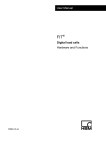
Transducer connection
10
Plug-in connection
Transducer
bu
rd
wh
bk
bu
gn
wh
Cable to
transducerelectronics
gy
bk
Cable shield
Fig. 3.1-3: Transducer connection in 4-wire circuitry via a 6-core cable extension
Fig. 3.1-4: Transducer connection in 4-wire circuitry without a cable extension
(jumpers 2 – 2‘ and 3 – 3‘)
HBM
AED9201B en
Transducer connection
11
When connecting several transducers, it is advisable to use an HBM junction box VKKx. In
general, the feed lines running to the AED should be shielded cables.
Notes on type of connection, length and cross-section of cables:
Depending on the bridge resistance of the load cell being used and the length and crosssection of the load cell connection cable, there may be voltage drops that can reduce the
bridge excitation voltage. The voltage drop at the connection cable is also dependent on
temperature (copper resistance). Likewise, the output signal of the load cell changes in proportion to the bridge excitation voltage.
6-wire circuit (standard mode of operation):
This will correct all the effects of the load cell cabling up to the feedback points. Even changing the length of a cable after calibration will not make any difference to the measurement
results.
For load cells with a 6-wire connection, feedback lines 2´ and 3´ are bridged in the load cell
with excitation 2 and 3 (Fig. 3.1-2). For load cells with a 4-wire connection, the feedback
bridges must be implemented directly at the load cell connection (Fig 3.1-3 or 3.1-4).
4-wire circuit:
As correction through AUTOCAL can only ever take place up to feedback points 2´, 3´, all
the changes of cable resistances affect the measurement result. This means that even if no
further changes are made to the 4-wire cable used for
calibration, there will still be measurement errors when there are temperature changes, because the cable resistance and possibly the contact resistances at the connectors are temperature-dependent. With the 4-wire circuit, feedback lines 2´ and 3´ are directly connected
at connection terminals 2 and 3 in the AED (see Fig. 3.1-4).
AED9201B en
HBM
Transducer connection
12
Equivalent circuit of the bridge with bridge resistance RB and supply lines with
line resistances RL1 and RL2:
RL1 = RL2 = (4 pCU /) (I [m] / A [mm2])
RL1
pCU = 0,0178 [ mm2/m] for copper
RB
RL2
UBR
 = 3,14
I = Length of cable, A = Cross-section of cable
 RL1 = RL2 = 1,6  bei I = 10 m and A = 0,14 mm2
The voltage drop over the bridge feeder cables can be determined from bridge resistance
RB, cable length l, cable cross-section A and the bridge excitation voltage:
UB + URL1 + URL2 = UBR
For
RB = 80 , RL1 = RL2 = 1.6  (l = 10 m) and UBR = 5 V
there is an excitation current of
IBR = UBR/(RL1 + RL2 + RB) = 60 mA
and thus a voltage drop over the two line resistances totaling approx. 0.32 V
(UBridge = 4.8 V).
For
RB = 80 , RL1 = RL2 = 16  (l = 100 m) and UBR = 5 V
there is an excitation current of
IBR = UBR/(RL1 + RL2 + RB) = 45 mA
and thus a voltage drop over the two line resistances totaling approx. 1.4 V
(UBridge = 3.6 V).
HBM
AED9201B en
Transducer connection
13
This is irrelevant for the 6-wire circuit, as the voltage drop over the sensor lines is taken into
account in the measurement signal.
But with a 4-wire circuit, the dependency of the copper resistance of the cables on temperature goes directly into the measurement result, as the bridge excitation voltage UBridge
changes:
RL(t) = RL20  (1 +   (t – 20 °C)),
where RL20 is the line resistance at 20°C and is the temperature coefficient of the copper.
RL20 – calculation see p. 13, CU := 0.00392 [1/K]
With a cable length of l = 100 m and a temperature differential of 10 °C, there is a line resistance of
RL1(t) = RL2(t) = 16  (1 + 0.00392  10) = 16.6 
This changes the bridge excitation voltage of
UBridge = 5.7 V (at 20°C) to UBridge = 3.53 V.
This change in bridge excitation voltage directly at the transducer changes the measurement
signal of the bridge by 1.9 % (= 100 %  (1 – 3.53 V / 3.6 V)).
This typical calculation shows that if long cables are involved, only 6-wire circuitry should be
used.
AED9201B en
HBM
Connecting the supply voltage
14
3.2
Connecting the supply voltage
The power supply must meet the following requirements:
AED9201B
DC voltage +15...+30 V (nominal 18...30 V)
Current consumption <175 mA (without bridge)
Current consumption <275 mA (for an 80  bridge resistance)
Fig. 3.2-1: Power supply connection
The voltage feed must be shielded. It can be applied within the interface cable or be implemented as a separate cable.
When supplying several AEDs via one cable, the voltage drop over the cable must be taken
into consideration. The voltage drop depends on the supply current required and on the line
resistance.
HBM
AED9201B en
Connection to a computer
3.3
15
Connection to a computer
The basic device can be set to two interface variants (changeover switch on the AED9201B
board).
Fig. 3.3-1: Pin assignment for the RS232 and RS485 interfaces
AED9201B en
HBM
Connection to a computer
16
No bus mode
The RS232 interface allows the AED to be connected directly to a PC. The cable length is
limited to 15 m and bus mode is not possible.
B
Fig. 3.3-2: Connecting an AED to a computer via the RS232 interface
HBM
AED9201B en
Connection to a computer
17
Bus mode
The RS485 interface with a 4-wire connection allows the full range of AED functions with a
maximum cable length of 1000 m. To connect the AED to the COM port of a PC (RS232),
you need an interface converter (1-SC232/422B from HBM).
Basically, shielded cables should be used for the interface wiring, with the cable shielding
being connected to the AED housing via the PG. (see AED9201B cable connection via the
PG gland). The power supply can also be connected via this cable, with a 6-core, shielded
cable being necessary.
If it should be necessary, a separate cable can be used to establish potential equalization
between the bus nodes. The cable shielding must not be used for this potential equalization.
For reasons of electromagnetic compatibility, it is advisable to use a double-shielded cable
(from the HBM program, for example: 3  2  0.14 m² , 4-3301.0076).
SUB-D connector
9-pin (PC)
PIN
2 = RxD
3 = TxD
5 = GND
SUB-D female connector
9-pin (converter)
PIN
2 = TxD
3 = RxD
5 = GND
Fig. 3.3-3: Connecting an AED to a computer via RS232 and the supply voltage
Die DTR control line for communication with the AED is not required.
AED9201B en
HBM
Multi-channel measurements (bus mode, RS485)
18
3.4
Multi-channel measurements (bus mode, RS485)
With the RS485 interface, several AEDs can be connected to a common bus line. The bus
cabling for 4-wire mode is shown in Fig. 3.4-1.
With the RS485 interface, up to 90 AEDs can be connected to a common bus line. With the
aid of the RS485 bus driver, it is possible to implement long cables (up to 1,093.61 yd in
length).
AED bus mode is set out as a Master-Slave configuration, with the AED implementing a
slave. This means that all the AED activities are initiated from the control computer. Each
AED is given a separate communication address (00...89) and can then be activated by an
Sii (ii = 00...89) Select command. A broadcast command (S98) is implemented for specific
communication situations. This means that after a command of this type, all the AEDs execute the command of the Master, but none of the AEDs respond. All these communication
commands are described with relevant examples in aed_help_e, AD103C, “Description of
the basic commands”.
Fig. 3.4-1: Bus structure 4-wire bus (general)
The termination resistances of 500  marked in Figure 3.4.1 are important for the electrical
function of the bus system. These resistances safeguard the quiescent level for the receiver
on the bus line. The physical circuit must only be connected with these resistances at the
line ends.
HBM
AED9201B en
Multi-channel measurements (bus mode, RS485)
19
For the local bus termination distribution shown in the diagram, the Master and the AED with
address 89 should include the termination resistances. Which is why, in this AED, the bus
connection is activated with the commands STR1; and TDD1; (see aed_help_e, AD103C;
“Description of the basic commands”).
The HBM interface converter also includes these bus termination resistances (do not deactivate them).
These terminations must not be activated more than twice in one bus. The wiring
must not be in the shape of a star. The best wiring method is to loop the physical
circuit through from AED to AED. The basic device has 2 PG cable entries for this.
The ground of the interface driver is related to the GND terminal. The interface driver
of the master should be also connected to this GND.
The quiescent level on the RS485 physical circuit is produced in 4-wire mode at:
TB - TA > 0.35 V
(Rest level though AED termination resistances)
RB - RA > 0.35 V
(Rest level though Master termination resistances)
As the RS485 is a differential bus interface, the rest level is also specified as a differential
voltage between the lines (and not ground-related). Furthermore, please note that this interface tolerates a maximum common-mode range of ±7 V.
AED9201B en
HBM
Connecting the diagnostic bus
20
3.5
Connecting the diagnostic bus
The diagnostic bus is used to analyze dynamic processes. The bus is set out as an RS485
2-wire bus (lines: TB/RB and TA/RA, GND).
Fig. 3.5-1: Connecting the diagnostic bus via terminal KL1
The interfaces setting of the bus is defined and cannot be changed (38400 bit/s, 8E1).
External bus termination resistances are not necessary for this bus.
The HBM interface converter can be used to connect the RS485 bus to an (RS232) COM
port of the PC.
HBM
AED9201B en
Connecting the diagnostic bus
21
Fig. 3.5-2: Diagnostic RS485 bus
The ground of the interface driver is related to the GNDext terminal. The interface driver of
the master should be also connected to this GNDext.
Only a connecting cable with a screen grounded on two sides should be used as the interconnecting cable between the AED 9201B and the bus and the master (see also:
AED9201B cable connection via a PG gland).
The functions and commands of the diagnostic channel are described in the help file
aed_help_e Diagnosis. The address corresponds to the address of the AD103C amplifier,
command ADR (00...89, factory setting: 31), see aed_help_e, Basic Commands). This address is independently from the CANOpen address.
The following functions can also be executed via this bus:
Parameters
Read only (changes are not possible)
Measured values
Reading individual measured values MSV?; (MSV?i not possible)
Results
Trigger results and dosing results can be read
The diagnostic functions can be executed using the HBM AED_Panel32 program (as from
Version V3.0.0).
The HBM display unit DWS2103 can be connected with this interface. Than all implemented
functions and parameters are accessible. This is independent from the main communication
channel.
AED9201B en
HBM
Connecting digital inputs/outputs
22
3.6
Connecting digital inputs/outputs
The measuring amplifier is electrically isolated from the supply voltage, the interface connection and the digital I/Os. These connections relate to the GND potential of the external supply
voltage.
Fig. 3.6-1: Connection of digital I/Os, inputs IN1/2 electrically isolated by ext. power pack 2
(IN1=trigger)
Inputs IN1/2 are electrically isolated from the external supply voltage UB , as well as from the
amplifier ground. The ground connection of both the inputs is initially connected to the
ground of supply voltage UB .
Logic level :
IN1: Trigger:
Break Dosing
IN2: Taring or start dosing
HBM
Quiescent level = low,
active edge = high-low edge
Quiescent level = low,
(duration 20 ms)
Activation = low-high-low-Puls
Quiescent level = low,
(duration 20 ms)
Activation = low-high-low-Puls
AED9201B en
Connecting digital inputs/outputs
23
Unused inputs remain open. If the input circuit is also supplied via UB, the ground of the
inputs and the ground of the UB must be connected.
Fig. 3.6-2: Connection of digital I/Os, inputs IN1/2 not electrically isolated from UB (same power
pack), (IN1 = trigger)
Digital outputs OUT1...6 are electrically isolated from the amplifier and are supplied via UB .
They are implemented as H-side switches. Consequently, consumers must be connected to
ground (see Fig. 3.6-2). The outputs are short-circuit-proof and can drive ohmic and inductive loads with currents up to approx. 0.5 A per output.
Logic level:
OUT inactive

voltage is Low (H-side switches deactivated)
OUT active

voltage is High (H-side switches activated)
The functions of the digital inputs and outputs differ in accordance with the type of measuring
amplifier used.
AED9201B en
HBM
Connecting digital inputs/outputs
24
Function of the digital inputs/outputs
The AD103 amplifier board has two inputs and 6 outputs. The functions are defined using
commands IMD, LIV and OMD (see aed_help_e, AD103C; “Description of the commands for
signal processing”, “Description of the commands for filling and dosing applications”).
Input functions:
IMD0:
Input functions deactivated, possible to read in the status using the POR command.
IMD1:
IN1 = external trigger for the trigger function (TRC),
IN2 = taring and changing over to net,
IMD2:
IN1 = Stop filling,
IN2 = Start filling
(dosing function)
Output functions:
IMD < 2 (no dosing mode):
LIV1 deactivated:
control OUT1 via POR command
LIV2 deactivated:
control OUT2 via POR command
LIV1 activated:
limit value LIV1 controls output OUT1
LIV2 activated:
limit value LIV2 controls output OUT2
LIV3 activated:
limit value LIV3 controls output OUT3
LIV4 activated:
limit value LIV4 controls output OUT4
Outputs OUT5,6 cannot be driven.
HBM
AED9201B en
Connecting digital inputs/outputs
25
IMD < 2 (dosing mode):
The following output functions are available, subject to the output mode command (OMD):
1)
Outputs
OMD0
OMD1
OMD2
OUT1
Coarse Flow
Coarse Flow
Coarse Flow
OUT2
Fine flow
Fine flow
Fine flow
OUT3
Ready signal /
emptying 1)
Ready signal /
emptying 1)
Ready signal /
emptying 1)
OUT4
Tolerance+ overrun
Outside Tolerance 
Alarm
OUT5
Tolerance– underrun
see command MUX
see command MUX
OUT6
Alarm
see command MUX
see command MUX
for emptying time = 0 (EPT)  OUT3 ready signal is after actual value determination,
for emptying time > 0 (EPT)  OUT3 emptying control is over set time
The command MUX is able to control the digital outputs OUT5 and OUT6 if the dosing mode
is activated (IMD = 0) and not used for the dosing control (OMD > 0).
AED9201B en
HBM
26
3.7
AED9201B cable connection
AED9201B cable connection via PG gland
Fig. 3.7-1: Cable connection via a PG gland
Only a connecting cable with a screen grounded on both sides (and metal connectors)
should be used as the connecting cable between the AED9201B and its partner device.
Bring the screen extensively into contact on both sides at the PG gland and at the metal
shell of the connector. If the partner device does not have a metal connector, connect the
cable shielding extensively to ground. If there are vast differences between the ground potential of the AED9201B and its partner device, a potential equalization line must be provided
in addition.
HBM
AED9201B en
Index
27
Index
4
4-wire circuit ...................................................................................................................................................11, 13
4-wire circuitry...................................................................................................................................................9, 10
4-wire connection................................................................................................................................................. 11
6
6-wire circuit ...................................................................................................................................................11, 13
6-wire connection..............................................................................................................................................9, 11
B
basic box ............................................................................................................................................................... 7
bridge excitation voltage .............................................................................................................................9, 11, 13
bridge resistance ............................................................................................................................................11, 12
bus
bus line ............................................................................................................................................................ 18
bus structure .................................................................................................................................................... 18
bus line................................................................................................................................................................ 18
bus mode........................................................................................................................................................16, 18
RS485.........................................................................................................................................................18, 19
bus termination .................................................................................................................................................... 18
bus termination RS485 ..................................................................................................................................... 18
C
cable connection.................................................................................................................................................. 22
cable connection – digital inputs ....................................................................................................................... 22
supply voltage .................................................................................................................................................. 26
cable connection supply voltage
cable connection AED9201B .......................................................................................................................14, 26
cable cross-section .............................................................................................................................................. 12
cable length ..............................................................................................................................................11, 12, 13
connecting the diagnostic bus .............................................................................................................................. 20
D
diagnostic bus...................................................................................................................................................... 20
distributor box ........................................................................................................................................................ 8
AED9201B en
HBM
28
Index
E
electrical connections............................................................................................................................................. 8
I
interface converter ............................................................................................................................................... 17
L
load cell connection ............................................................................................................................................... 8
M
manufacturer’s notes ............................................................................................................................................. 6
mechanical construction......................................................................................................................................... 7
multi-channel measurements ............................................................................................................................... 18
P
PG gland ..........................................................................................................................................................8, 26
potential equalization ........................................................................................................................................... 17
profibus.................................................................................................................................................................. 4
Q
quiescent level
RS485.............................................................................................................................................................. 18
R
RS232 ................................................................................................................................................................... 6
RS422 ................................................................................................................................................................... 6
S
serial interface ....................................................................................................................................................... 6
RS232................................................................................................................................................. 6, 7, 15, 17
RS422................................................................................................................................................................ 6
RS485.........................................................................................................................................................15, 17
supply voltage...................................................................................................................................................... 14
supply voltage AED9201B ...........................................................................................................................14, 26
HBM
AED9201B en
Index
29
T
transducer connection............................................................................................................................................ 8
U
use ........................................................................................................................................................................ 6
AED9201B en
HBM
Modifications reserved.
All details describe our products in general form only.
They are not to be understood as express warranty
and do not constitute any liability whatsoever.
Hottinger Baldwin Messtechnik GmbH
Postfach 100151
D-64201 Darmstadt
Im Tiefen See 45
D-64293 Darmstadt
Tel.: +49/6151/803-0 Fax: +49/6151/8039100
I1693-2.0 en
E-mail: [email protected] · www.hbm.com