1
ECE 477 Final Report
Spring 2005
Team 9: Nathan Smith, Omar Shaikh, Ryan Koors, Jeff Huston
Team Code Name: ___________G.I.M.P._______________________ Team ID: __9__
Team Members (#1 is Team Leader):
#1: _Jeff Huston_________________ Signature: ____________________ Date: _________
#2: _Ryan Koors_________________ Signature: ____________________ Date: _________
#3: _Omar Shaikh________________ Signature: ____________________ Date: _________
#4: _Nathan Smith_______________ Signature: ____________________ Date: _________
ECE 477 Final Report
Spring 2005
REPORT EVALUATION
Component/Criterion
Score
Multiplier
Abstract
0 1 2 3 4 5 6 7 8 9 10
X1
Project Overview and Block Diagram
0 1 2 3 4 5 6 7 8 9 10
X2
Team Success Criteria/Fulfillment
0 1 2 3 4 5 6 7 8 9 10
X2
Constraint Analysis/Component Selection
0 1 2 3 4 5 6 7 8 9 10
X2
Patent Liability Analysis
0 1 2 3 4 5 6 7 8 9 10
X2
Reliability and Safety Analysis
0 1 2 3 4 5 6 7 8 9 10
X2
Ethical/Environmental Impact Analysis
0 1 2 3 4 5 6 7 8 9 10
X2
Packaging Design Considerations
0 1 2 3 4 5 6 7 8 9 10
X2
Schematic Design Considerations
0 1 2 3 4 5 6 7 8 9 10
X2
PCB Layout Design Considerations
0 1 2 3 4 5 6 7 8 9 10
X2
Software Design Considerations
0 1 2 3 4 5 6 7 8 9 10
X2
Version 2 Changes
0 1 2 3 4 5 6 7 8 9 10
X1
Summary and Conclusions
0 1 2 3 4 5 6 7 8 9 10
X1
References
0 1 2 3 4 5 6 7 8 9 10
X2
Appendix A: Individual Contributions
0 1 2 3 4 5 6 7 8 9 10
X4
Appendix B: Packaging
0 1 2 3 4 5 6 7 8 9 10
X2
Appendix C: Schematic
0 1 2 3 4 5 6 7 8 9 10
X2
Appendix D: Top & Bottom Copper
0 1 2 3 4 5 6 7 8 9 10
X2
Appendix E: Parts List Spreadsheet
0 1 2 3 4 5 6 7 8 9 10
X2
Appendix F: Software Listing
0 1 2 3 4 5 6 7 8 9 10
X2
Appendix G: User Manual
0 1 2 3 4 5 6 7 8 9 10
X2
Appendix H: FMECA Worksheet
0 1 2 3 4 5 6 7 8 9 10
X2
Technical Writing Style
0 1 2 3 4 5 6 7 8 9 10
X5
CD of Website Image and Reports/Poster
0 1 2 3 4 5 6 7 8 9 10
X2
TOTAL
Comments:
-ii-
Points
ECE 477 Final Report
Spring 2005
TABLE OF CONTENTS
Abstract
1.0 Project Overview and Block Diagram
2.0 Team Success Criteria and Fulfillment
3.0 Constraint Analysis and Component Selection
4.0 Patent Liability Analysis
5.0 Reliability and Safety Analysis
6.0 Ethical and Environmental Impact Analysis
7.0 Packaging Design Considerations
8.0 Schematic Design Considerations
9.0 PCB Layout Design Considerations
10.0 Software Design Considerations
11.0 Version 2 Changes
12.0 Summary and Conclusions
13.0 References
Appendix A: Individual Contributions
Appendix B: Packaging
Appendix C: Schematic
Appendix D: PCB Layout Top and Bottom Copper
Appendix E: Parts List Spreadsheet
Appendix F: Software Listing
Appendix G: User Manual
Appendix H: FMECA Worksheet
-iii-
4
4
6
9
13
19
22
27
34
38
43
49
51
53
A-1
B-1
C-1
D-1
E-1
F-1
G-1
H-1
ECE 477 Final Report
Spring 2005
Abstract
The General Informative Medical Prosthetic provides sensory feedback for leg
amputation patients by mapping combinational pressure differentials under the prosthetic foot
and lower-leg angle measurements to distinct vibrating patterns around the remaining appendage.
The system offers modes for the direct mapping of simulated sensory feedback, as well as modes
to run rehabilitation training programs which affectively train the patient on how to walk
correctly with a prosthetic leg. The General Informative Medical Prosthetic also offers the
ability to upload bio-statistical measurements via an Ethernet interface to a standard web
browser, thus giving medical professionals the ability to monitor patients remotely.
1.0
Project Overview and Block Diagram
The G.I.M.P. system serves as a patient sensory interface to existing prosthetic legs.
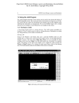
Figure 1.1 shows the system composition as represented by a block diagram. A standard
walking shoe, outfitted with an array of four pressure sensors, outputs analog voltage levels
which are measured via an Analog-to-Digital (ATD) port on a Freescale MC9S12NE64CPV
microcontroller. The microcontroller is interfaced to an Ethernet port which provides the
G.I.M.P. system the ability to upload and tabulate bio-statistical information to a web browser
terminal. An LCD is interfaced to the microcontroller and an RPG comprises the on-board user
interface. Software modules provide the capability to either directly transfer pressure
differentials to the vibrating motor array, or to execute “training programs” in which the patient
is prompted to apply different orientations of pressure (thus aiding in the prosthetic adaptation
process). The vibrating motors are connected in parallel to pull-up NPN MOSFET amplifiers
(Class D) which allow for the 100mA current requirement of each motor. The power system is
comprised of one 7.2V NiCd RC battery which is interfaced with a power supply outputting 5V,
-5V, and 3.3V via parallel LM switching MOSFET circuits. Main battery power is monitored by
one ATD pin and battery status is displayed on the LCD where “[###]” represents a full battery
and “[
]” represents an empty battery.
1
ECE 477 Final Report
Spring 2005
Vibrating
motors
BJT
amps.
LEDs
Reset
Button
Network
Applications
(data upload)
Power Supply:
RPG
7.2Vdc RC
car battery
Ethernet
device
RESET PORT
PORT
MC9S12NE64
ATD
DC Switching
Regulator
Power supply
+/- 5Vdc reg. 3.3 Vdc reg.
LCD
Fused 7.2 supply
Amplifier
Circuit
Shielded cable
Clinometer
Pressure
Sensors
Figure 1.1 – G.I.M.P. Block Diagram
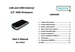
All hardware and software systems are confined to units which are easily mountable on
existing prosthetic legs, as well as on the human leg (for testing purposes). Each vibrating motor
is accompanied by an LED which provides visual indication of the device’s operation. Figure
2.1 shows the completed G.I.M.P. system being worn by a testing subject (mounted on human
leg for preliminary testing).
Figure 1.2 – Completed G.I.M.P. System
2
ECE 477 Final Report
2.0
Spring 2005
Team Success Criteria and Fulfillment
2.1
Criterion 1: “The ability to detect pressure changes in the shoe via an ATD port
on a microcontroller and to map those pressure differentials to distinct vibrating
patterns in a vibrating motor strap.”
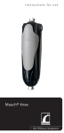
This success criterion is fulfilled as the device clearly
maps unique patterns from the pressure sensors in the shoe to
the vibrating motors strap. When each motor turns on, it’s
Vibrating
motors are
mapping
pressures
corresponding LED turns on which shows the “distinct
vibrating patterns” required. The LEDs are rather dim
because they are intended for operation at 5 volts and, during
device operation, they are receiving a duty cycle waveform
with maximum voltage of 3 volts. Figure 2.1 shows the
device demonstrating Criterion 1 and Criteria 2.
Figure 2.1 Demonstration of
success criteria 1 and 2
2.2
Criterion 2: ”The ability to execute sequential vibrating patterns, thus providing
‘how-to-walk’ training capabilities”.
A sequential training program can be executed which vibrates all motors
until detecting the beginning of the operator’s gait phase (indicated by a reading
taken from the clinometer). Once the step begins, only the motors in the back of
the strap are enabled, thus indicating to the user that the heel should be placed on
the ground. When it is determined that the heel is firmly on the ground, the
motors on the side of the leg vibrate, followed by the motors at the front at the
leg, thus indicating to the user that weight should be transferred to the front of the
foot. The routine restarts when the clinometer marks the beginning of the step
(when the angle of the knee with respect to the thigh is minimized).
3
ECE 477 Final Report
2.3
Spring 2005
Criterion 3: “The ability to record sensor data and upload to a computer via
Ethernet connectivity.”
Figure 2.2 is a screen shot of an internet browser receiving data from the
G.I.M.P. device. As the type of information being transmitted during the Ethernet
routine can be selected by
the doctor, each is
indexed and tabulated,
thus allowing for easy
integration into such
programs as Excel and
Matlab. For
demonstration of this
success criteria, the data
Figure 2.2 Demonstration of success criteria 3
being displayed is the time in the previous mode (in minutes), the device’s on
time (in minutes), and the number of steps taken in direct map mode.
2.4
Criterion 4: “The ability to display system status (mode, battery level) on an
LCD.”
Figure 2.3 is a shot of the G.I.M.P. system’s LCD which displays the
current mode on the top line and mode being pointed to by the RPG on the bottom
line, along with the battery level (where
“[###]” is a full battery and “[
]” is an
empty battery). mode is used to send data to
the LCD.
Figure 2.3 Demonstration of success criteria 4
4
ECE 477 Final Report
2.5
Spring 2005
Criterion 5: “The ability to automatically determine when the prosthetic is idle
and enter into a power-conservation mode in which certain functions/ports will be
turned off (some ATD, LCD, etc).”
Power conservation mode is entered when the microcontroller detects
inactivity in the foot sensors. During this time, the device turns off ATD and
PWM pins to conserve power. To exit out of power conservation mode, the
device can either be reset, or the RPG can be pressed. During the testing of this
success criterion, the idle time was set to approximately 1 minute, after which
time the device went into power conservation mode.
5
ECE 477 Final Report
3.0
Spring 2005
Constraint Analysis and Component Selection
3.1
Introduction
The design is a system that supplements existing prosthetic legs and provides the patient
with some sensory feedback about the pressures on the foot through an array of vibrating motors
worn on a strap around the thigh. The system will use four small pressure sensors placed in the
insole of a shoe and a clinometer at the knee to record information about pressure on the base of
the foot and which phase of stride a patient is in at the time. All of the sensors output an analog
signal, which will be measured using an ATD port on the selected microcontroller. The
microcontroller uses these sensor inputs to determine where there is pressure on the foot and
activates the appropriate motors, which will be connected using bipolar junction transistor (BJT)
amplifiers to supply sufficient current to operate the motors. The microcontroller will use
memory to store statistics about how the patient has been walking and allow it to be uploaded via
an Ethernet connection. The system will also use software that will allow the execution of
“training programs” in which a light vibration from the motors prompts the patient to make
movements and apply pressure in the proper order while they are learning to walk with the
prosthetic. To distinguish between modes the microcontroller will also interface with a 16x2character display that can display mode and other information. A rotary pulse generator will also
be interfaced with the microcontroller in order to allow the patient to control the mode of the
system. Finally, because the system must be portable it needs to be battery powered using a
battery that will allow for a reasonable operational time between charges and will display the
current battery level on the LCD.
3.2
Design Constraint Analysis
3.2.1 Computational Requirements
The microprocessor must be capable of calculating the average of the values read from
the four pressure sensors in the foot to determine where pressure is being placed on the foot. It
must also be able to resolve an analog signal with at least a 1V resolution and refresh the LCD
display. The most important requirement is that processes be completed in real time so that the
sensory feedback corresponds to the pressure that is being applied to the foot at a specific time.
6
ECE 477 Final Report
Spring 2005
3.2.2 Interface Requirements
The design requires several interface connections. Each of the four pressure sensor
inputs and the clinometer input require ATD conversion. The 10 vibrating motors will be driven
using BJT amplifier circuits and can be interfaced with a single I/O pin for each motor. The
LCD display will require 11 pins to interface directly with the microcontroller [1]. The rotary
pulse generator interface will require three pins. The Ethernet interface being used is built into
both microprocessors that are under consideration.
3.2.3 Power Supply Constraints
The design requires a portable power source capable of providing a number of different
supply voltages. The pressure sensors use an amplifier circuit that will require a 7.2 and -5 V
supply voltages and draw no more than 2.5 mA [2]. The microprocessor will require a 3.3 V
supply voltage. All CMOS parts require a 5 V supply. The clinometer requires a supply in the
range of 5V to 15V with a 9V nominal value and draws only 0.5 mA of current [3]. The LCD
requires 5 V and will draw 1.2 mA [1]. The largest power consumption will occur in the
vibrating motors which operate at 3 V and can draw 100 mA each [4]. There is also a possible
interface to off-chip memory that may be required to store the statistical data recorded.
3.2.4 Packaging Constraints
The design must be sufficiently small so that it will fit easily onto a prosthetic leg and can
be worn under clothing. The vibrating motor strap must also fit easily under clothing and must
be comfortable enough to be worn for extended periods. The pressure sensor array must be able
to be placed easily in the insole of a typical shoe and must be able to measure pressure at the
point where each sensor is located uniquely. The overall weight of the system should be light
enough that the weight of the system and prosthetic combined does not exceed the weight of a
typical human leg. Therefore, the device has a target weight of 2.5 lbs with an estimated
maximum of 5 lbs. In addition, in order to be practical, the device must be able to withstand
some exposure to the elements. Therefore, the entire system must be at least water resistant and
should be able to operate within a reasonable temperature range from 50 to 95 degrees
Fahrenheit as an example.
7
ECE 477 Final Report
Spring 2005
3.2.5 Cost Constraints
The cost of the design should be as low as possible to keep the final consumer cost
reasonable. However, due to the nature of the system, the cost will be moderately high. The
final cost will be in the area of $500 due in large part to the sensor requirements of being small
and having a resolution that will allow the detection of small pressure and orientation changes.
3.3
Rationale
The pressure sensors constitute the first major component block. Because of the
packaging constraints of the sensor array, the pressure sensors need to be very thin and have a
relatively small area of measurement. The Transducer Techniques® Subminiature Compression
Only Load Button SLB Series Load Cell was considered as an initial candidate. A thickness of
0.250 inches combined with the price of $395 per unit as specified in [5] made the package
larger than ideal and far too expensive. The second pressure sensor candidate was the
Flexiforce® A201 Standard Force & Load Sensor. According to the Flexiforce® datasheet [2],
the device is only 0.208 mm thick and has a sensing area of 9.53 mm, which fit well into the area
where the sensors will be located. In addition, the price of these sensors was only $55 for a pack
of four, which made it a much better choice in order meet cost constraints.
The second major component to be selected was the clinometer. The first possible sensor
was the Omron Micro Tilt Sensor D6B. This sensor measures a tilt angle using two discrete
output pins as shown in datasheet [6]. This met the design’s basic requirements, but a discrete
output would limit that ability of the system to detect small changes in the angle of the lower leg.
This led to the selection of the AccuStar® Electronic Clinometer with radiometric output as the
final choice for the design. The specific clinometer selected was the AccuStar® clinometer
model with radiometric output and a horizontal flange mount. According to the manufacturer
datasheet [3], this sensor operates like a potentiometer with a linear analog output relative to
ground and whose voltage is selected by the supply voltage. This allows a much greater
resolution and fits the design requirements of tilt measurement better than the Omron sensor.
The only drawback was the high price of the sensor at $139, but no other sensor could be
identified which fit the requirements at a lower cost.
The final major component selection was the choice of a microcontroller. One of
the most important constraints on the microprocessor is the need for Ethernet connectivity.
8
ECE 477 Final Report
Spring 2005
Based on this constraint the Rabbit Semiconductor RCM3700 RabbitCore and Freescale
Semiconductor MC9S12NE64 were selected as candidates because of their integrated Ethernet
capabilities. Both microprocessors would meet the computational requirements of the design,
but there are differences in the amount of on chip storage and available I/O pins. The RCM3700
offers more storage with up to 512 K of flash, 31 configurable I/O lines, and 2 fixed outputs [7].
The MC9S12NE64 only has 64 K of flash, but offers up to 70 I/O lines [8]. With the number of
required I/O lines near 30, the MC9S12NE64 was selected because it allows more available lines
for debugging and expansion. The additional I/O lines also allow for the possibility of
interfacing with off-chip memory to compensate for the smaller on-chip flash.
3.4
Major Components
Description
FLEXIFORCE
SENSORS
SENSOR
CLINOMETER
HORIZONTL
FLNG
VIBRATING
MOTORS
MC9S12NE64V1
Vendor
Part Number
Tekscan
A201-100
AccuStar
02110102-000
Sanko Electric
freescale
semiconductor
Unit Cost
Quantity
Total Cost
$13.75
4
$55.00
$139.00
1
$139.00
1E120
$1.25
10
$12.50
MC9S12NE64CPV
$0.00
1
$0.00
9
ECE 477 Final Report
4.0
Spring 2005
Patent Liability Analysis
4.1
Introduction:
As the primary focus of the G.I.M.P. device is adaptability to fit a large variety of
prosthetic legs, it is not intended to compete with existent prosthetics themselves, but rather is
meant to be an optional tool used by patients who wish to expedite their recovery time in a more
autonomous manner than is currently available. The prosthetic itself is not modified at all in the
operation of the device and in fact, the device can be demonstrated on any individual as it can fit
onto a human leg as well as a prosthetic. Therefore it is necessary not only to examine prosthetic
patents, but also patents involving all of the peripheral devices used by the G.I.M.P. system
including shoes equipped with pressure sensors, vibrating motor feedback devices, and the use of
clinometers to measure the angle of the lower foot.
4.2
Results of patent search:
There are numerous existing devices that serve the same
function as the in-shoe pressure sensor array and the
vibrating motor strap. One device was found in which
pressure sensors in the foot of a prosthetic are interfaced to
vibrating motors around the existing limb, thus serving
essentially the same function as the G.I.M.P. system. The
following sections will elucidate each similar device found
on the United States Patent and Trademark Office search
engine [1].
Figure 4.1: System for
continuously measuring forces
applied by the foot (US patent #
5,678,448
10
ECE 477 Final Report
4.3
Spring 2005
Existing Devices Similar to G.I.M.P. Peripherals:
There exists a sensor array (pictured in figure 4.1) which is intended to perform essentially
the same task of measuring pressure changes of the foot on the
ground. In the G.I.M.P. system, these pressure changes are
interpreted by the microcontroller before being mapped to
vibrating motor patterns. Two patents exist for this footshaped pressure sensor array for detecting pressures applied by
the foot and pressures applied on the foot [2] [3], each
corresponding to a different configuration of the device.
While the G.I.M.P. system measures the position of the
prosthetic relative to the ground using a clinometer, another
device accomplishes essentially the same function by
measuring the prosthetic’s position relative to the patient’s leg.
Figure 4.2: Sensor device for
monitoring a prosthetic device (US
Patent #5,840,047)
As described by its patent, “The sensor and alarm system for monitoring a relative position of a
prosthetic device with respect to the residual portion of an amputee's limb includes a battery
power supply; a proximity sensor for generating a position signal indicative of the relative
position of the prosthetic device and the residual portion in the prosthetic device near the residual
portion, and an alarm device for signaling when the prosthetic device is located in an injurious
position or positions.”[4] A picture of the sensor for monitoring a prosthetic device is shown in
Figure 4.2. Note that the sensor itself is notably different than the clinometer used on the
G.I.M.P. system, but the functionality it provides is practically identical (determining the
position of the prosthetic).
11
ECE 477 Final Report
4.4
Spring 2005
Existing Devices Similar to
Overall G.I.M.P. System:
Only one US Patent was found which
essentially captivates the overall functionality of
the G.I.M.P. system. The system and method
for providing a sense of feel in a prosthetic or
sensory impaired limb [6] is an apparatus for
providing a person with stimuli corresponding
to an external operation on a sensor of a
prosthetic device used in conjunction with a
prosthetic or sensory impaired limb. The
specific limb mentioned in the US patent is the
leg and, therefore, this system provides the
same functionality of one of the success criteria
of the G.I.M.P. system; mainly, “The ability to
Figure 4.3: System and method for
providing a sense of feel in a
prosthetic or sensory impaired limb
(US Patent #:6,500,210)
detect pressure changes in the shoe via an ATD
port on a microcontroller and to map those pressure differentials to distinct vibrating patterns in a
vibrating motor strap.” A picture of this patented device can be seen in Figure 4.4. Note that the
device has both pressure detection sensors as well as vibrating motors located around the existing
appendage, although the system is a complete prosthetic itself rather than a system that can be
added to an existing prosthetic (like the G.I.M.P. system).
4.5
Analysis of patent liability:
In the following section, each of the “similar” devices found in the patent search will be
analyzed under the terms of literal infringement and infringement under the doctrine of
equivalents as the two types of infringement have been defined in the following ways: If the
potentially infringing product or process literally has all of the limitations recited in a claim, it is
said to “literally infringe.” However, even if one or more elements or limitations are not literally
present, the potentially infringing product or process might still be found to infringe under an
equitable doctrine developed by the courts, called the “Doctrine of Equivalents.” While no
patents were found that infringe with the overall G.I.M.P. system in all aspects, there are several
12
ECE 477 Final Report
Spring 2005
areas of possible infringement centric around the system’s peripheral devices and individual
success criteria. The patents listed below were filed in 2001.
4.6
Analysis of Patent #5,323,650 and #5,678,448 with Respect to the G.I.M.P
System:
The pressure sensor for the foot and the corresponding configuration patent (sensor lies
between the foot and the shoe) would infringe with the foot sensors of the G.I.M.P. system under
the definition of literal infringement since each system provides identically the same features.
This infringement, however, would not be a legal issue since the G.I.M.P. system is built from
and is therefore inclusive of this particular patent. The pressure sensors used between the foot
and the shoe of the G.I.M.P. system were purchased from the company which owns rights to
patent #5,323,650 and #5,678,448. In other words, because we are not attempting to
manufacture the same device but rather to integrate it into a larger system, no patent
infringement would occur as long as the foot pressure sensors were purchased from the
FlexiForce ® Corporation prior to installation.
4.7
Analysis of Patent #5,840,047 with Respect to the G.I.M.P System:
As was noted in the description of its patent, this method for measuring the position of the
prosthetic leg uses a reference to the remaining appendage rather than in reference to ground.
Under the definition of each type of patent liability, the G.I.M.P. system and this patent “perform
[essentially] the same task” but, because they do so in different ways and using different
technologies, there would be no patent infringement. It should be noted that the type of sensor
used by this patent may actually minimize the volume occupied by the G.I.M.P. system should it
be utilized, but the cost of the associated royalties would have to be considered before it would
be integrated into the system. As it is, no infringement occurs, but the G.I.M.P. device is
potentially not as efficient as it could be.
4.8
Analysis of Patent #5,775,332 with Respect to the G.I.M.P System:
While this patented device is not intended to be used by patients with leg amputations, it
provides much the same functionality as is described by the operation of the G.I.M.P. system.
Mainly, each device “provides bio-sensory feedback to the patient” in a way that is meant to aid
13
ECE 477 Final Report
Spring 2005
with rehabilitation. This device teaches patients who have suffered strokes how to walk again by
using sequential feedback patterns like those that are performed in the motor strap of the
G.I.M.P. system. Although the two systems provide much the same function in much the same
way, the literal specificity of the G.I.M.P. system sets it apart from this patent. As long as the
device is marketed as being intended specifically for prosthetic patients and not for stroke
victims, there should not be any infringement. This could be an issue as far as immediate
demonstration goes as the inventors of the G.I.M.P. system are planning on demonstrating it on a
human leg. Should the device be demonstrated for actual consideration, it is recommended that a
model be used with an actual prosthetic limb.
4.9
Analysis of Patent #6,500,210 with Respect to the G.I.M.P System:
This patent proposes the largest possibility of patent infringement to the G.I.M.P. system.
While this patented device is intended to communicate pressure differentials in the foot to
vibrations around the existing appendage, it does so through an already-integrated prosthetic
limb whereas the G.I.M.P. system is intended as a “addable system” to existing prosthetics. This
means that, while it provides the same function, it does so in a substantially different way.
Furthermore, the G.I.M.P. system is capable of many other modes (like training mode) as it
incorporates a microcontroller which has the capacity to execute programs. This function is not
described by Patent #6,500,210. For these reasons, it has been determined that the G.I.M.P.
device does not infringe on this patent under the definition of “literal infringement”, although it
may infringe under the doctrine of equivalents since one of its modes provides direct sensory
feedback (no stored sequential program is executed in this mode).
4.10 Action Recommended:
As it has been determined that there is possible patent infringement under the doctrine of
equivalents with patent #6,500,210, some device modifications and marketing strategies will
now be suggested to prevent such infringement. Firstly, when the G.I.M.P. device is being
considered for a patent, it should be emphasized that the device provides a unique function by
acting as an “addable system to existing prosthetics” and thereby does not infringe with patent
#6,500,210 as it provides its function in a substantially different way. The difference could be
compared to a car-mounted CD player versus a portable CD player (each of which holds its own
14
ECE 477 Final Report
Spring 2005
unique patent currently). Secondly, in order to ensure that the G.I.M.P. system does not
infringe, it is recommended that that “direct sensory” mode be eliminated from the device. This
means that the G.I.M.P. system would only execute training programs rather that directly
communicate pressures on the bottom of the foot to vibrations around the leg. While substantial
functionality would be lost, it is clear that the device would still be of clear value to the
recovering amputee and would, without a doubt, be patentable under US law.
15
ECE 477 Final Report
5.0
Spring 2005
Reliability and Safety Analysis
5.1
Introduction
Since our device will most likely be used by patients who would have trouble walking with
an ordinary prosthetic, there is a chance one could become dependant on the sensations to walk,
and a failing prosthetic could confuse them, causing them to trip and fall. While we feel that
extensive field testing would need to be done to show this dependence to be the case, we have
chosen to be cautious and will still consider multiple motor failures to have a high criticality.
Since each discrete “instruction” to the user makes use of multiple motors, however, we will
deem a single malfunctioning motor an “inconvenience” and therefore label it a “semi-critical”
failure. The acceptable failure rate for this “semi-critical” failure will be explained in the
reliability analysis section of this document, and is higher than the standard 10-9 failure rate for
failures resulting in possible safety hazards.
5.2
Reliability Analysis
1. Microcontroller MC9S12NE64CPV
λP = [C1 * ПT + C2 * ПE] * ПQ * ПL [1]
where:
C1 – die complexity (16 – bit [4]) = 0.28
ПT – temperature coefficient (T < 125oC [4]) = 3.1
C2 – Pin constant (112 pins [4]) = 0.046
(Interpolated between 80 and 128 pin table entries of 0.032 and 0.053 [1])
ПE – Environmental Constant (Ground Mobile) = 4.0
ПQ – Quality Factor (Commercial) = 1.0
(Commercial is normally 10, but Dr. Johnson indicated in lecture that a
value of 1 should instead be used for ПQ)
ПL – Life Constant (In production for about six months [4]) = 1.8
Thus:
λP = [0.28 * 3.1 + 0.046 * 4.0] * 1.0 * 1.8
λP = 1.894 failures per 106
MTTF = 1/ λP
MTTF = 5.28E5
16
ECE 477 Final Report
Spring 2005
2. Step Down and Inverting DC/DC Converter LTC1174HV-5
λP = [C1 * ПT + C2 * ПE] * ПQ * ПL [1]
where:
C1 – die complexity (assumed 301 to 1000 transistors) = 0.04
ПT – temperature coefficient (T < 125oC for linear MOS device [5]) = 58
C2 – Pin constant (8 pins [5]) = 0.026
ПE – Environmental Constant (Ground Mobile) = 4.0
ПQ – Quality Factor (Assumed Class B) = 1.0
ПL – Life Constant (In production for over two years [5]) = 1.0
Thus:
λP = [0.04 * 58 + 0.026 * 4.0] * 1.0 * 1.0
λP = 2.424 failures per 106
MTTF = 1/ λP
MTTF = 4.13E5
3. Transformer CTX100-4
λP = λB * ПQ * ПE [2]
where:
λB – Base failure rate (THS = 125oC, Max Operating Temp = 130oC [6]) = 0.016
ПQ – Quality Factor (assumed less than MIL-spec) = 30
ПE – Environmental Constant (Ground Mobile) = 12
Thus:
λP = 0.016 * 30 * 12
λP = 5.76 failures per 106
MTTF = 1/ λP
MTTF = 1.74E5
4. Switching Transistor BJT 2N3704.
λP = λB * ПT * ПA * ПR * ПS * ПQ * ПE [3]
where:
λB – Base failure rate (NPN [7]) = 0.00074
ПT – temperature coefficient (T < 100oC [7]) = 4.2
17
ECE 477 Final Report
Spring 2005
ПA – Application Factor (switching) = 0.70
ПR – Power Factor (Pr < 1W ) = 1.0
ПS – Stress Factor (0 < VS < 0.3) = 0.11
ПQ – Quality Factor (Plastic DIP) = 8.
ПE – Environmental Constant (Ground Mobile) = 9.0
Thus:
λP = 0.00074 * 4.2 * 0.70 * 1 * 0.11 * 8 * 9
λP = 0.0172 failures per 106
MTTF = 1/ λP
MTTF = 5.804E7
5.3
Conclusions
The microcontroller, switching and inverting DC regulator and the transformer all had
failure rates in the 10-6 range, which may be acceptable as these would lead only to system
failures of low criticality. In addition, these calculations used fairly conservative estimates,
especially when dealing with maximum temperate ranges. The failure rates could be further
minimized by adding heat sinks and will also decrease due to the power conservation techniques
we will be implementing with our design.
The switching transistor could potentially lead to a safety risk, however, as described in
the introduction. 10-9 is generally considered an acceptable failure rate for failures that can lead
to personal injury for the user. In this case the failure rate for the switching transistor is in the
10-8 range, somewhat higher than the 10-9 normally used as the guideline. The vibrating motor
strap has ten different motors on it, however, each with its own switching transistor. Given that
the discrete sensations being sent to the user will be using multiple vibrating motors at a time, the
malfunctioning of only one BJT will fall far short of rendering the device useless and will
certainly not result in a risk of personal injury for the user. The malfunctioning of two motors is
still unlikely to pose a safety risk, but if we are conservative and do in fact say that two
malfunctioning motors will cause a safety hazard, the failure rate of two independent BJTs is
then (1.72 * 10-8)2 = 2.95 * 10-16, which certainly falls within the 10-9 acceptable range for a
critical failure.
18
ECE 477 Final Report
6.0
Spring 2005
Ethical and Environmental Impact Analysis
6.1
Introduction
This document details the ethical and environmental impact of the General Informative
Medical Prosthetic (G.I.M.P.) device being developed by group nine. The device is intended for
use with existing lower limb prosthetics as an accessory or as integrated technology that aims to
resolve bringing the sensation of walking back to lower limb amputees through the use of
electronic sensors and motors. The device is intended to be used for normal daily use if it is
integrated into current prosthetic designs. If not, it can be used as a training tool by doctors in
order to aid new amputees in learning how to walk with lower limb prosthetics. This report
outlines the ethical challenges that must be resolved in bringing the design to market including
sufficient testing of the medical device to abide by both in-house and federal regulations, placing
clear and concise warning labels and providing extensive user documentation to make incorrect
use of the product clear to the user, and adding safety mechanisms for critical failures of the
device. This report also outlines the environmental impact the design will have at various stages
of its life cycle including techniques used in the production of the device, proper maintenance by
the user during its useful life, and proper disposal and recycling of the various components used
to construct the device.
6.2
Ethical Impact Analysis
Due to the nature of the G.I.M.P. device as a medical product, it is of vital importance
that the product is safe for use and that any and all critical failures possible are found during
testing cycles and addressed through warning labels, documentation, and safety mechanisms to
ensure proper functionality in order to aid individuals who require or desire use of the product.
In order to bring the product to market, extensive testing in a variety of conditions will be
necessary in order to meet in-house guidelines and reliability specifications as well as federal
guidelines and regulations. For example, the device will be classified as a “medical device” in
accordance with the U.S. Food and Drug Administration by its following definition: “an
instrument, apparatus, implement, machine, contrivance, implant, in vitro reagent, or other
similar or related article, including a component part, or accessory which is: intended for use in
the diagnosis of disease or other conditions, or in the cure, mitigation, treatment, or prevention of
19
ECE 477 Final Report
Spring 2005
disease, in man or other animals, or intended to affect the structure or any function of the body of
man or other animals, and which does not achieve any of it's primary intended purposes through
chemical action within or on the body of man or other animals and which is not dependent upon
being metabolized for the achievement of any of its primary intended purposes” [1]. Due to this
classification, the device will be subject to both premarketing and postmarketing regulatory
controls and approvals through extensive testing and validation studies. These regulations
include the placement of proper warning labels to inform the user of immediate dangers with
improper use of the device. For example, in order to prevent potential electrocution, warning
labels must be provided that explicitly communicate to users environments and uses for which
the product was not designed including environments where it will be exposed to water, such as
in the rain, shower, etc. and so must be powered down unless the device is integrated with waterproof prosthetics. Lastly, before the product can be brought to market, it is also necessary that
safety mechanisms be added to the design as critical failures are found during the testing and
evaluation cycles in order to ensure user safety when/if the device enters unexpected states.
In order to address the ethical challenge of properly testing the device before bringing it
to market extensive test cases and test plans will have to be developed over multiple test cycles
in order to find as many faults with the device as possible before the product is sent for review
by the FDA. A significant portion of these testing cycles will include operation of the device in
various environments in addition to its intended use in a doctor’s office or in the patient’s home.
For example, it is quite likely that the device will not provide enough simulation of walking with
a real leg to assure a user that he/she will be able to hike a trail or scale a mountain. Although
these may be extreme examples, it is important that the documentation provided with the device
make the user aware of the limitations of the device in returning “full-functionality” back to their
lower limb. In addition, testing will also help in determining the specifications of the device,
such as the useful life of the device and how much time a user has to replace the battery in the
device once the device enters a “battery-low” mode.
Providing warning labels is a challenge due to the limited space available directly on the
device. There are several important warnings that must be made clear to the user, such as: the
device uses a battery and so should not be placed or left in hazardous areas (in direct sunlight),
the device should not be exposed to water while in use, and that the battery should be replaced or
recharged as soon as possible after the device enters a “battery-low” mode should the use of the
20
ECE 477 Final Report
Spring 2005
device be critical. Placing every warning label possible on the device, however, is not acceptable
since then it is entirely possible that the labels will simply be ignored. Usability studies may lead
to findings that describe which warning labels are most effective and/or needed for the device
and so testing will hopefully lead to the development of effective product warning labels. In
addition to the warning labels, extensive documentation will have to be written for the product
before it can be released to market outlining additional warnings and precautions that must be
taken into consideration when using the device.
Although the “battery-low” mode is a safety mechanism developed at the time the device
was prototyped, additional testing will very likely expose critical failures that can be addressed
through safety mechanisms. For example, one critical failure that is quite possible is the output
motor strap of the device vibrating erratically during either the direct-mapping or learning
modes. In either situation, the output to the user may be confusing, disorienting, and if the user
is in a dangerous environment, incorrect operation of the device could potentially cause him/her
harm. A safety mechanism that could be put in place to prevent such a situation from happening
could perhaps be an emergency stop button to immediately cut power to the output vibrating
motors, or a software routine to monitor the output to the motors and ensure proper behavior by
perhaps resetting the device if erratic output is detected.
Extensive testing and reviews are necessary for all three components of the ethical
challenges faced in bringing the product to market. Through extensive testing, additional critical
failures, safety mechanisms, user behavior can be studied to improve the device and create a
reliable, safe, and effective product.
6.3 Environmental Impact Analysis
As with the large majority of electronic devices, there is a significant concern with the
environmental impact of the G.I.M.P. device due to the hazardous materials contained in the
electronic components used in its construction. These hazardous materials have the potential to
harm the environment and even humans through contamination of water-supplies and potentially
even food-sources [7, 8].
During production of the device, lead is used in both the traces placed on the printed
circuit board in addition to the solder used to populate the board. Lead is a heavy metal that can
harm both the environment, through contamination, and humans through ingestion from water,
21
ECE 477 Final Report
Spring 2005
foods, etc. This manufacturing process undoubtedly will produce waste lead that will have to be
disposed of properly so as not to contaminate the nearby environment possibly even putting
human lives at risk. In addition, the device will be produced with a Nickel-Cadmium (Ni-Cd)
dry-cell rechargeable battery that the user will have to be aware of so the device is not placed in
hazardous environments (in direct sunlight, in extreme temperatures, in water, etc.) during
normal use. Doing so could cause the battery to leak and/or explode potentially causing harm to
the user and/or the environment. Proper disposal and recycling is of significant importance with
the device due to the use of the Ni-Cd battery and the lead found in the printed circuit board.
Improper disposal of the battery or the printed circuit board can lead to contamination of the land
and/or the air due to the heavy metals contained in both components.
In order to reduce the risk of contamination to the environment during production of the
device, it is possible to seek alternative printed circuit board production methods through the use
of lead-free printed circuit board fabrication. According to Bob McGrath of Printed Circuit
Design & Manufacturing, “Upcoming methods to attain lead-free fabrication include using
electrolytic nickel/gold for PCB surface finishes and tin, silver, and copper (SnAgCu, SAC)
alloys for soldering instead of tin/lead alloys” [2]. Part of the drive for lead-free electronics
production is due to the upcoming European Commission directives 2002/95/EC and
2002/96/EC, or the Restriction of Hazardous Substances in Electrical and Electronic Equipment
(RoHS) and the Waste Electrical and Electronic Equipment (WEEE) directives respectively, that
will go into full effect July 1, 2006 [3, 4]. These directives affect all parties involved in
manufacturing, selling, distributing, recycling, or treating electrical and electronic equipment in
Europe and so will affect policies in effect worldwide. World-leading test and certification labs
such as the Underwriters Laboratories Inc. have already initiated compliance programs to adhere
to the new directives [5]. One potential source where the G.I.M.P. printed circuit board could be
manufactured “lead-free” includes the PCBexpress fabrication company [6].
Warnings, recommendations, and unambiguous documentation will have to be provided
to inform the user of the dangers to the environment should the device and battery be mishandled
or not maintained properly. These labels and documentation will have to explicitly state which
environments the device should not be used in or left in. It may potentially be effective to
include plausible damages to the environment should the device not be disposed of or recycled
properly with an emphasis of how such damage could affect the user.
22
ECE 477 Final Report
Spring 2005
Lastly, in order to address the environmental concerns with the disposal and recycling of
the product, both extensive documentation and potential recycling plans could be put in effect to
curb potential harm to the environment. For instance, documentation can provide lists of
authorized recycling companies and locations for both the Ni-Cd battery as well as the printed
circuit board. If partnerships with authorized recycling corporations like the Rechargeable
Battery Recycling Corporation (RBRC) could be made in order to streamline the process of
returning the Ni-Cd batteries, users could be given both instructions on how and where to return
their batteries and incentives such as rebates for returning their batteries in order to encourage
proper recycling of the batteries instead of improper disposal The RBRC is a non-profit, public
service organization created to promote the recycling of portable rechargeable batteries [7]. A
similar service could be provided to reduce the negative environmental impact caused by the lead
in the printed circuit board should lead-free production not be feasible. With respect to products
integrated into prosthetic devices, collaborations could be made with retailers to initiate a “reuse
& recycle” program in which used prosthetics returned to retailers could be purchased by or
donated to the manufacturer where the prosthetic shell could be reused, the lead in printed circuit
boards could be recycled, and the batteries could be removed and shipped to authorized recycling
services like the RBRC.
23
ECE 477 Final Report
7.0
Spring 2005
Packaging Design Considerations
(All G.I.M.P. packaging pictures can be found in Appendix B)
7.1 Introduction
The system was developed to interface to or fit on current lower limb prosthetics and so
size and weight were critical design constraints that the team faced since a device that is either
too bulky or too heavy will not fit a lower limb prosthetic and/or would eliminate any significant
positive experience perceived by a lower limb amputee. Furthermore, with a small design, the
end product or technology could feasibly be marketed to existing prosthetic device
manufacturers as a system that could easily be added to their products either as a marketable
accessory, or as a technology that could be integrated with their devices. For testing and
prototyping purposes, the device was built as an accessory for existing prosthetic devices. This
added characteristic required that the packaging of the design be modular and easily fitted to
existing prosthetics.
7.2 Packaging Specifications and Design
The group first learned of commercial products similar to the design when team member
Nathan Smith read an article about a bionic prosthetic device in the February issue of WIRED
magazine. After informing the group, significant research was done in order to determine if
commercial products exist that fulfill the project’s desired functionality. Although the group did
not find any products that directly address returning the sensation of walking to lower limb
amputees, several similar products including the C-Leg® by Otto Bock® [1] and the Rheo
Knee™ by Össur [2] were found. Both commercial products are similar to the design; however,
they focus on using electronics and sensor systems to correct the function of the prosthetic
device and ease the process of walking for the amputee, whereas the group’s product focuses on
returning the sensation of walking to the lower limb amputee. This key difference leads to
unique constraints for both the commercial products as well as the group’s product, including
significant packaging design differences. The following provides an in-depth analysis of the two
24
ECE 477 Final Report
Spring 2005
similar commercial products found by the group mentioned above: the C-Leg® and the Rheo
Knee™.
I. C-Leg® by Otto Bock® [1]
Figure 1. C-Leg® by Otto Bock®
The C-Leg® is marketed as a smart prosthetic device that able to think for you using
inbuilt sensors and a micro-controller to adjust itself, providing both stability and security to
lower limb amputees. The packaging of the device includes a knee angle sensor at the top of the
frame of the device that measures the flexion angle and the angle speed of the knee joint and a
moment sensor that measures the moments of flexion by strain gauges in the ankle area. Both of
these sensors along with the microcontroller and a rechargeable battery are found within a carbon
fiber frame that provides high stability and yet is very light. As one can see in Figure 1., the
frame of the device is quite compact allowing the user to easily conceal the device under a pant
leg or skirt.
7.2.1 Positive aspects of the commercial product’s packaging
The most attractive feature of the C-Leg® beyond its technological capabilities is most
definitely its attractive, discrete design. The packaging of the design allows the user to either
show off their prosthetic with its stylish frame or hide the prosthetic simply by covering the
device with their lower garment (a pant leg, long skirt, etc). Furthermore, according to the
25
ECE 477 Final Report
Spring 2005
device’s documentation [1], the user can easily switch between special activity settings including
a cycling and “permanent standing” mode simply by tapping the toe of the device.
7.2.2 Negative aspects of the commercial product’s packaging
A negative aspect of the C-Leg® packaging also lies with the compactness of its design.
Although the ability to conceal a prosthetic device requires that it be compact, the C-Leg®
package produces an unsymmetrical imbalance between the size of the prosthetic and the size of
an actual leg when the device is not concealed with a user’s lower garment. This imbalance can
lead to undesired attention and a perceived state of not being normal as is sought for the user by
the prosthetic’s manufacturer.
7.2.3 Adapted aspects of the commercial product’s packaging
The prosthetic is marketed as a device that can make the user both look and feel as close
to normal as possible. The team hopes to adapt the attractive, aesthetic features of the C-Leg®
package into their design since they envision it will be used in conjunction with prosthetic
devices like the C-Leg®. This necessitates a package that will provide the user the option to
either show off the device as a stylish, high-tech accessory or conceal the device thereby
preserving Otto Bock’s goal to make the user look and feel as close to normal as possible. In
order to achieve these features, the packaging must be compact and visually pleasant.
7.2.4 Unique aspects of our project’s packaging
The most unique aspect of the project’s packaging that differentiates it from the C-Leg®
is that it can be interfaced to and used in conjunction with lower limb prosthetic devices like the
C-Leg®. The C-Leg® employs many similar technologies found in team nine’s product;
however, it is packaged as a stand-alone prosthetic device whereas the team’s device is packaged
most like a prosthetic device accessory. This detail alone provided a unique set of constraints
when deciding on the package design. Unlike the C-Leg®, the team was not limited by the
significant amount of mechanical constraints that must be addressed when developing a full
26
ECE 477 Final Report
Spring 2005
prosthetic device that must support the weight of the user. Furthermore, since the team
developed the system as an accessory, modularity is an additional constraint in the design. In
order to address this, the product packaging was split into four distinct units: two sensor input
units, one central processing and display unit, and one sensor output units.
II. Rheo Knee™ by Össur [2]
Figure 2. Rheo Knee™ by Össur
The Rheo Knee™ is a state-of-the-art lower limb bionic device developed by Össur. The
device is marketed as a bionic device as opposed to a prosthetic device because of its use of
electronics, sensor systems, and artificial intelligence to bring the user “unprecedented natural
movement.” As can be seen in Figure 2, the packaging of the system does a stellar job at hiding
the complexity of the device. The Rheo Knee™ employs a vast array of technology including a
dynamic learning algorithm that allows the device to learn a particular user’s walking style in
order to optimize swing control, a magnetorheological actuator that varies the devices knee
resistance in real-time, a microprocessor controlled stance that safeguards against disturbances in
the user’s path and potential stumbles or falls, and a self-calibrating operating mode.
7.2.5 Positive aspects of the commercial product’s packaging
A positive aspect of the Rheo Knee™ package is its discrete design. Like the positive
aspect of the C-Leg® package, the Rheo Knee™ can be hidden from others underneath a lower
garment, however, the package is also quite effective at concealing potentially intimidating
electronics from the user him or herself. Such a complex system could intimidate or brood
mistrust in users who know or care little for the technology employed by the bionic device. The
27
ECE 477 Final Report
Spring 2005
simple, yet effective packaging eliminates the user’s need to interact with or regard the innards
of the design, allowing a clean human-machine interface.
7.2.6 Negative aspects of the commercial product’s packaging
A negative aspect of the Rheo Knee™ package is that it is simply just a knee. Unlike the
C-Leg® unit, the Rheo Knee™ is not a full prosthetic device since the prosthetic foot
mechanism must be purchased separately. This specification requires that there be an additional
connection between the bottom of the knee and the top of the foot mechanism. Although
modular systems can often be beneficial, having to construct ones prosthetic from multiple
devices, and potentially maintain separate parts of the prosthetic using different methods may be
an inconvenience to the user.
7.2.7 Adapted aspects of the commercial product’s packaging
A key attractive feature of the Rheo Knee™ package is that it nicely conceals the
complexity and technology of the device allowing the user to simply see an object that can help
them acquire a better walking experience. The team was able to implement this feature with
both its foot pressure sensor system as well as its output vibrating motor system by concealing
the complexity of the sub-system designs behind their packaging. The user need only know that
they can clip the vibrating motor strap around their leg, and place their prosthetic foot on the
foam sensor pad, and it will operate in the way the team and user desire. The team also hopes to
employ this feature with their main module design, by creating a simple interface that will allow
the user to quickly switch between learning/operating modes without requiring an understanding
of how the system works.
7.3 Unique aspects of our project’s packaging
The most unique aspect of the project’s packaging that differentiates it from the Rheo
Knee™ is that it again is a design that can be interface to and used in conjunction with lower
limb prosthetics and bionics like the Rheo Knee™. The Rheo Knee™ employs electronics and
28
ECE 477 Final Report
Spring 2005
sensors to address several significant concerns with regard to correcting a user’s gait and aiding a
user with “swing control,” however much like the C-Leg®, it is packaged as a stand-alone
prosthetic/bionic device capable of handling multiple requirements of a safe and stable
prosthetic, whereas the project is to be used as an accessory to return the sensation of walking to
the user. This facilitates the team’s decision to make a compact, lightweight, modular design
that can easily be interfaced with a variety of prosthetic/bionic devices.
7.4 Materials List
Description
7.5” x 4.3” x 2.2” Polycarbonate enclosure [3,4]
2.5” Black Strap & Connectors
2.5” x 1” Black Cloth
Foam Foot Pads
Cork Sensor Covers
Wire & Input Connectors
Quantity
1
6
1
2
4
6
7.5 Tooling Requirements
Minor modifications to the polycarbonate enclosures were done in order to create
adequate spacing for the printed circuit board to fit snuggly in the box. This was performed
through the use of a milling machine.
7.6 Estimate of Packaging Weight and Unit Cost
-Estimated Package Weight
Description
Vibrating Motors & Strap
Clinometer Sensor & Strap
Foot Sensors & Foam Pad Package [5]
Total for I/O modules
Est Weight (grams)
15
10
5
30
7.5” x 4.3” x 2.2” Polycarbonate enclosure [3,4]
Battery
PCB Board and components for main module
LCD
Total for main module
30
40
30
30
130
Overall Estimated Weight
160
29
ECE 477 Final Report
Spring 2005
7.7 Estimated Package Cost
Description
7.5” x 4.3” x 2.2” Polycarbonate package [3,4]
15” Black strap & Clips
Input/Output connectors & Twisted wire
Screws and Nuts
Foam materials [5]
3M Velcro
Total
Price ($)
7.00
5.00
5.00
1.00
5.50
3.50
$ 27.00 / unit
We estimate that the total packaging weight of both the main processing unit as well as
the on-board peripherals is approximately one-hundred and sixty grams, and will cost
approximately twenty-seven dollars per unit. We estimate that our overall design costs will be
approximately six hundred dollars.
30
ECE 477 Final Report
8.0
Spring 2005
Schematic Design Considerations
8.1
Introduction
The design is a system that supplements existing prosthetic legs and provides the patient
with some sensory feedback about the pressures on the foot through an array of vibrating motors
worn on a strap around the thigh. The system will use four small pressure sensors placed in the
insole of a shoe and a clinometer at the knee to record information about pressure on the base of
the foot and which phase of stride a patient is in. All of the sensor output signals will be
interpreted by the microcontroller which uses these inputs to determine where there is pressure
on the foot and activates the appropriate motors. The microcontroller will also use non-volatile
memory to store statistics about how the patient has been walking and allow it to be uploaded via
an Ethernet connection. The system will also use software that will allow the execution of
“training programs” in which a light vibration from the motors prompts the patient to make
movements and apply pressure in the proper order while they are learning to walk with the
prosthetic. To distinguish between modes the microcontroller will also interface with a 16x2
character display that can display mode and other information. A rotary pulse generator will also
be interfaced with the microcontroller in order to allow the patient to control the mode of the
system. Finally, because the system must be portable it will be battery powered and will display
the current battery level on the LCD. This document will detail the dataflow of the design and
explain the rationale behind the circuit design.
8.2 Theory of Operation
8.2.1 Pressure Sensors
The Flexiforce® A201 Standard Force & Load Sensors are designed to act as force
sensing resistors and are used to detect the pressures in the sole of the shoe. In order to receive
an output voltage proportional to the input pressure the manufacture recommends an operational
amplifier circuit as shown in the sensor data sheet [1]. This circuit is used as the basis for the
pressure sensor amplifier/filters portion of the circuit. The modified circuit also acts as a filter to
help reduce noise picked up by the long leads of from the sensors. Filtering is achieved using
capacitors whose values were determined through experimentation until noise was sufficiently
reduced. The circuit uses a LM324 quad op amp package, which only requires a 7.2V and
31
ECE 477 Final Report
Spring 2005
ground connection instead of an op amp requiring +9 and -9 V, reducing the number of required
supply voltages. Also included in the circuit are potentiometers connected to the op amp outputs
to adjust the gain of the circuit.
8.2.2 Clinometer
The Accustar® Electronic Clinometer with radiometric output is designed to act like a
potentiometer. It is being used to detect the angle of the lower leg relative to the horizon. It
requires a 3-pin connection consisting of signal (output), ground, and a supply voltage of 5V to
15V regulated according to the datasheet [2]. Output resolution is directly proportional to input
voltage; however, a supply voltage of 5V is used because it is already required on the circuit
board to supply CMOS parts and this choice helps to reduce the number of required power
supply voltages in the overall design. While this choice provides less resolution than higher
voltages, it is still sufficient for the design. A 5V supply also guarantees that if the circuit is
functioning properly, there will never be more than 5 volts output to the microcontroller, which
has an absolute maximum input voltage of 6.5V.
8.2.3 Microcontroller
The microcontroller used in the design in the Freescale MC9S12NE64CPV which
operates on a supply voltage of 3.3V. The MC9S12NE64 was chosen primarily because it
includes 70 I/O pins and an integrated Ethernet controller, which can be used to upload recorded
device usage data. The use of this integrated controller requires that the chip operate at 25MHz.
This is achieved using a 25MHz crystal oscillator circuit. The basic interface of the
microcontroller to the external crystal, RJ45 connector, and background debug mode (BDM)
header used for programming is based on the manufacturer recommended circuit shown on page
550 of the datasheet [3], with the addition of a run/load switch on pin 26 to upload programming.
The pressure sensor and clinometer output signals are interfaced to the microcontroller through
the ATD ports on pins 85-89. An additional ATD port on pin 90 is used to monitor the battery
level using a voltage divider to reduce the 7.2V battery level to approximately 1.3V. The
vibrating motor outputs are connected to pins 99-100 and 103-108 and will use pulse width
32
ECE 477 Final Report
Spring 2005
modulation to drive a BJT transistor circuit, which in turn drives the motors. The LCD display
will use an 8-bit databus, read/write, and chip enable signals, and will be connected to pins 13,
16-19, 22-25, and 27-19 using general I/O. The last component interfaced to the microcontroller
is a rotary pulse generator with a momentary switch that will be used to input user selections into
the microcontroller. The RPG has seven pins with two connecting to the microcontroller on
general I/O pins 11 and 12 for the RPG and one connecting on pin 10 for the momentary switch.
Finally, in addition to interfaces with other components, all of the pins on the microcontroller are
connected to 28 pin headers that will surround the chip and allow for easy debugging or easy
access to all pins should design changes be necessary.
8.2.4 Motors
The vibrating motor strap used to relay information to the user contains Sanko Electric
Vibrating Motors operating at 3V and up to 100mA [4]. In order to meet the current requirement
of the motors, BJT amplifier circuits controlled by the microcontroller are used. The amplifiers
were designed using resistor values that would cause the transistors to operate in saturation and
limit current. Because the amplifiers are connected directly to the microcontroller, Schottky
diodes are places across the amplifiers to help protect the microcontroller from current spikes.
8.2.5 LCD
The Crystalfontz CFAH1602A-RGB-JP LCD is used to display mode and battery
information and has a 16-pin interface with an 8-bit databus [5]. The LCD module requires a 5V
supply voltage for logic and a 3.8V supply voltage for the LCD. Both voltages are drawn from
the 5V regulated supply with the 3.8V being achieved through a voltage divider. Non power
pins are interfaced to the microcontroller.
8.2.6 Power Supply
The power supply is built around a 7.2V RC battery because it is a commonly available
rechargeable battery with a reasonable charge capacity and provides sufficient voltage. It uses a
33
ECE 477 Final Report
Spring 2005
LTC1174HV-5 to generate +5V and -5V regulated supplies and a LTC1174-3.3 to generate a
3.3V regulated supply. These regulators were chosen because they are able to supply the
required voltages and are able to meet the current requirements of the design. The circuits used
are example application circuits shown on pages 16 and 12 of the LTC1174 datasheet [6] under
typical applications.
34
ECE 477 Final Report
9.0
Spring 2005
PCB Layout Design Considerations
9.1
Introduction:
The purpose of this design project has been to build an attachable system for existing
prosthetic legs which would allow patient to “feel” the pressure changes under his artificial foot
via a vibrating motor strap worn around the remaining appendage. Pressure detection occurs in
thin-film pressure sensors located in a sandal which feeds a variable dc voltage to the ATD port
on the microcontroller (a HC12 variant) via four integrating amplifiers which provide noise
reduction capabilities. Once sensor data
management occurs in the microprocessor,
PWM signals are generated and delivered to
ten class D amplifier circuits consisting of
Schottky diodes in parallel with NPN
bipolar junction transistors. The power
supply for the system generates 5 volt, -5
volt, and 3.3 volt regulated outputs and one
unregulated, fused 7.2 volt supply. The
(a) PCB Design for smaller acrylic box:
5”x3”x1.5” (overly-complex version)
switched main power comes from a 7.2 volt
remote control car battery which is to be
located under the PCB during final
installation. During layout, the class D
amplifiers, the integrating amplifiers, the
power supply, and the microcontroller will
all need to be isolated as much as possible
on the PCB.
9.2
PCB Layout Design
Considerations
(b) PCB Design for larger acrylic box:
7”x4”x2” (cleaner version)
Figure 2.1 - Layout Options for Two Potential
PCB Containers
In constructing the PCB for the G.I.M.P. system, considerations were made in the areas
of electrical, mechanical, and anatomical necessity. Merging the physical dimensions of the
actual device, the environmental conditions under which the device is expected to operate and
35
ECE 477 Final Report
Spring 2005
the corresponding electrical implications given thereby, the PCB was designed to meet all
requirements. These design constraints will now be examined in greater detail:
9.3
Physical Constraints on the PCB
As the G.I.M.P. device is intended to be an addable system to existing prosthetic legs, it is
exceeding important that the physical dimensions of the device be minimized so that minimal
volume is occupied in close proximity to the prosthetic itself. An undesirable design would be
one in which the patient had to wear a “box” which was clearly visible through the clothes. The
selected container for the PCB has two available sets of internal dimensions [1] for which two
individual PCB layouts were designed. One acrylic box occupied approximately 5”x3.5”x1”
while the other occupied 7”x4”x1.5”. A conceptual image of each PCB layout can be found in
Figure 2.1 which illustrates the graphical complexity of each layout option (note: Figure 2.1b
does not include the copper pour for understandability purposes. Among the criteria yet to be
discussed, one of the most important in selecting our final layout choice was the complexity of
the PCB itself. For the smaller of the two boxes, only 90% routing could be completed and over
100 vias were required. For the larger box, only about 50 vias were needed and all routing could
was completed efficiently. In this sense, although the larger of the two potential boxes was
selected to accommodate our final PCB design, it satisfies the physical constraint of occupying a
minimum volume.
As stated, the dimensions of the selected acrylic box are 7”x4”x2”, although the internal
dimensions are not rectangular but rather reflect the internal construction of the box [1]. As
such, the PCB for the G.I.M.P system is outlined by a trace on the global layer (marked by the
edge of the copper pour) which follows the shape of the inside of the box, navigating around six
posts distributed throughout the box. The PCB will be mounted to the case itself with metal
separators and bolts mounted through the bottom of the box. Four mounting holes were added to
the PCB to accommodate these requirements. As the internal depth of the box is 2”, it was
necessary that the PCB be designed to require no greater depth. As the two largest components
for the PCB were the 50uH inductor and RJ-45 connector, the sum of these to thicknesses
determined the maximum width of the board if both sides were populated. The thickness of
these components is less than 1.5”, and so it was determined that both sides of the PCB could be
36
ECE 477 Final Report
Spring 2005
populated while leaving ample room inside of the case for jumper cables to the motor strap,
sensor array, and battery. Figure 2 illustrates the width considerations for the PCB.
RJ-45 Jack
1.5”
2”
Axial Inductor
Battery
Figure 2 – Width considerations for PCB Layout
It must be assumed that the PCB will be subjected to the same environmental conditions
that a human leg would be subjected to throughout the course of daily life. While the acrylic box
will provide ample isolation between the electronics and the surrounding environment, all
electronics will be subject to the same electrical conditions that the patient may experience. For
this reason, a copper pour was added to the top and bottom layers of the PCB to aid in grounding
any EMI that may come from the environment (for instance, if the patient drags his feet along
turf and generates significant charge).
9.4
Electrical Constraints for the PCB
Due to the close proximity of the digital and analog components imposed by our
packaging constraints, it was very important that there be maximal isolation between
components located within a small area. For this reason, it was chosen that a copper pour be
added to both sides of the board which, while typically used for isolation in circuits using RF
components [2], would also provide isolation between the class D amplifiers (located on the right
of the board) and the microcontroller (located on the far left). Because the class D amplifiers
operate with a variable pulse in the form of a square wave, it was noticed that there may be
significant noise in the high frequency components which make up the square wave. While these
noise components would have little effect on the robust digital circuitry, the analog to digital
converters for the foot pressure sensors could be affected. For this reason, it was decided that the
ATD circuitry (consisting primarily of a quad op amp, four potentiometers, and several
37
ECE 477 Final Report
Spring 2005
capacitors) be located as close to the microcontroller as possible as to minimize the distance
between the ATD amplifier outputs and the actual ATD ports on the HC12. The same strategy
was taken with our clock and bypass capacitors which are also located directly next to and under
the microcontroller respectively.
Another concern, also related to the ATD circuitry is the long “artificial ground” lines
feeding into the four op-amps. Because the operation of the op amp involves the amplification
of a voltage difference between the inverting and non-inverting inputs, any noise on the ground
line (which runs all the way down to the foot) would be amplified prior to being fed into the
HC12’s ATD. To minimize noise along these ground lines, copper foil was placed around the
sensors themselves, and coiled-pair wires lead between the headers on the PCB to the sensors.
When tested with various sources of noise in the lab (e.g. switching sparks), the measures taken
were shown to be highly affective and what little noise could not be compensated for through
PCB layout techniques would not be sufficient to affect to operation of the overall device.
Trace sizing was determined on the amount of current which was anticipated to be passed
through each wire in a given net. For all digital circuitry, no more than a few milliamps would
be passed into or out of the microcontroller and, for this reason, 12 mil tracing was used with the
exception of the lines leading from the headers into the microcontroller itself which were chosen
to be 8 mils. An 8 mil trace can handle currents on the orders of a couple hundred milliamps
(this number varies with the material used for the trace, the thickness of the trace, and the
temperature of operation)[3]. The thickest traces on the board are the 40 mil power traces. If all
circuitry is being powered (including all 10 motors which draw about 100 milliamps each), no
more that 1.5 amps will be drawn across any power rail. 40 mil traces are rated to approximately
1.8 amps [3] and were deemed sufficient for our design. To protect against current spikes, a fuse
was added to the power supply to ensure safe operation (more precisely, electrical isolation of
the supply power in the event of a surge in current) above the rating for the power traces.
It should be noted that through-hole parts were chosen for all analog circuits including
the class D amplifiers for ease of installation and for testing purposes (through-hole parts provide
affective testing points). To provide the same capabilities around the microcontroller, all
microcontroller pins have been wired directly to headers. Should the PCB be manufactured
during post-development, it should be noted that ample volume would be saved if these headers
were omitted and only surface-mount components were used.
38
ECE 477 Final Report
Spring 2005
Any footprints which were not readily available in existing libraries were generated
directly from the manufacturer specifications. The components included the RPG, RJ-45 jack,
Power and Run/Boot switches, fuse, power jack, and reset pushbutton. Before the PCB was sent
out for manufacturing, all components were “tested” against the generated footprints. No errors
were observed.
39
ECE 477 Final Report
Spring 2005
10.0 Software Design Considerations
The microcontroller chosen for our project is the MC9S12NE64CPV (NE64). The NE64
uses the CodeWarrior compiler that allows programming of the micro to be done in C. Freescale
offers some free C code for use with the NE64 [2] which we have used for the basis of our
program (register and port initializations, etc.) and into which we have inserted our own code for
our core software modules.
10.1 Memory Model
The NE64 has 64 KB of programmable, non-volatile Flash memory and 8 KB of volatile
SRAM. We anticipate the Flash being more than sufficient for amount of code storage that will
be needed, but the 8KB of SRAM was a cause for some concern and caused a small modification
in how we planned on using the Ethernet capabilities. Originally, we had considered recording
sensor input data while the user is at home for some period and storing this information in
SRAM to later be uploaded at the doctor’s office. Because the size of the SRAM is so limited,
however, the patient will do his or her sample walking at the doctor’s office (either on a treadmill
or around the room if the cord is long enough) and the data will be uploaded through the Ethernet
while it is being recorded.
10.2 Memory Map
The memory for the NE64 is mapped as follows[1]:
40
ECE 477 Final Report
Spring 2005
The 8K of RAM in Figure 1-2 above is a volatile portion of memory where variables are stored,
while 16K sections of fixed Flash EEPROM are non-volatile and store the actual code that are
programmed into the microcontroller.
10.3 Startup Code
Startup code is already provided within the OpenTCP C code we are using as the basis
for the code for our project [1]. On a cold boot, _premain() and then main() will be called. In
addition, this startup code will automatically be called on a chip reset. We have modified this
main() function to include the initialization of I/O ports as well as the ATD and hardware
interrupts (for Pulse-Width Modulation). The LCD screen is also initialized on startup.
41
ECE 477 Final Report
Spring 2005
10.4 Organization of Embedded Application Code
The code for our project is best categorized as loop driven. The major functionality of
our project involves continuously polling the sensory inputs on several ATD ports, interpreting
the data, and then driving the motors in the motor strap accordingly. In direct-mapping mode,
for example, our system will continuously monitor the pressure sensors. When a sensor detects a
certain amount of pressure it will drive the corresponding motor(s). The Motor Output module
initially “drives” each of the ten motors with a 0% duty cycle, which results in no vibration.
Duty cycle then changes to 100% when particular sensory input data is received.
10.5 Software Design Narrative
The code for this project can be broken up into seven primary modules: Main/Startup,
Liquid Crystal Display (LCD), Analog-to-Digital Sensor Inputs (ATD), Sensor Data
Management (SDM), Motor Output, Power Conservation (ATD + Battery Monitor), and
Ethernet.
10.5.1 Main/Startup
This module was touched on earlier in the report. After some initial code is executed at
startup or reset, main() is called. Main() handles the initialization of I/O ports as well as the
ATD, hardware interrupts (for Pulse-Width Modulation), and modules. These initializations
consist only of setting control registers to activate the built in modules on the chip. The LCD
screen is also initialized on startup. Our code for initializing the LCD was adapted from [3]
using knowledge we acquired from [4].
10.5.2 Liquid Crystal Display (LCD)
The LCD is initialized in the main() function, and as mentioned was adapted from
published code [3] to accomplish this. Timer interrupts were used to fit the timing characteristics
of the LCD during initialization. The same source also included code to display characters on
our LCD, which was adapted for our purposes.
42
ECE 477 Final Report
Spring 2005
10.5.3 Analog-to-Digital (ATD)
ATD capabilities are built into the NE64 and are quite simple to utilize. The ATD is
initialized by setting control registers to select bit precision, among other things. 8-bit precision
was chosen, which more than satisfied the needs for this project. This is used to measure the
force being exerted onto each of the pressure sensors, as well as to measure the angle of the
patient’s leg, which is measured by the clinometer.
10.5.4 Sensor Data Management (SDM)
SDM is the next step after the ATD sensory input. In this module, the input from the
ATD is fed into a lookup table which determines whether the sensor input values are above the
required threshold. In direct mapping mode, the table entry will refer to which motors must be
driven when the sensors are determined to be at particular values. In the training mode,
however, this lookup table will be used in a slightly different way. This time, there will be an
expected pressure/angle value that will be compared against the actual value of the sensor inputs
provided when the user is walking. If the expected value is met, the next stage of Training is
entered.
10.5.5 Motor Outputs
10 motors can be driven at separate times according to the sensory input data through the
ATD. In Direct Mapping mode, when the ATD inputs are determined to be over a specific
threshold value, the appropriate motors are driven in the vibrating motor strap. This is done by
simply setting the correct output ports. In Training mode, on the other hand, specific motor
“instructions” are given (again by setting the appropriate output ports), and when the expected
sensory values are satisfied, the device moves to the next stage of the training process. A
flowchart describing the function of the Direct Mapping and Training Modes is provided in
Figure 2 below.
10.5.6 Power Conservation
The Power Conservation mode in our system will also be run using the ATD module.
There are two things that cause the prosthetic to enter Power Conservation mode. The first
occurs if the battery is low (this is measured by simply the voltage output of the battery being put
43
ECE 477 Final Report
Spring 2005
into an ATD channel). The second occurs if the prosthetic has been idle for a specified amount
of time (if the user is standing in place, enough pressure is exerted on the sensors to prevent the
device from entering the idle state). To determine when the device is idle, a global counter is
added which increments every time the ATD detects no sensor input, and then clears again when
the ATD does change. After the counter has reached a value that is sufficiently high, the
prosthetic will enter into power conservation mode. An RPG button press will wake the system
up from this idle mode. Battery-level induced power conservation mode, however, will not wake
up when you touch the RPG. A new battery is needed and the system will not be restored to full
strength without one.
10.5.7 Ethernet
The Ethernet module is built in to the NE64 and is a big reason we chose this particular
MCU in the first place. Since there is only one-way data transfer this module is not expected to
be a terribly difficult module to implement. It is, however, also the one we know the least about.
10.6 Software Documentation
This section will use flowcharts to explain how the modules will be implemented, and
also includes a list of functions with a short description of how each works.
Figure 10. 2: Direct Map and Training Modes Flowchart
Initialize Motor
Duty Cycles to “0”
Mode?
Training
Send vibrating
“instruction” signal
Direct Map
Wait for Sensor to Reach
Expected Value
Drive Motors if
Corresponding Sensor
Reading is Above
Defined Threshold
Next Training Stage
44
ECE 477 Final Report
Spring 2005
Table 10.1: Function List
Function Name
void main()
void LCD_WriteString(char[] String, int Line)
void Power_Down(int Low_Battery)
int Send_Packet(struct Packet *Ready)
int Get_Closest(int Value)
int Motor_Lookup(int Value)
int ATD_Value(int Sensor_Num)
Comments / Description
Initializes ATD, Motor Output, LCD, and I/O
pin directions
Writes the string passed to this function onto
either the first or second line of the LCD
Puts the system into conservation mode.
Low_Battery indicates the reason for the
Power_Down and determines whether an RPG
push button will wake the system up or not (if
Low_Battery don’t wake up)
Sends the packet pointed to by *Packet to the
doctor’s computer via an Ethernet cable.
Returns 0 on success.
Returns the closest value that will match a
table lookup value. In reality this just takes
Value and removes some of its precision.
Samples all the ATD ports and drives the
motors accordingly
Returns the ATD input of the sensor indicated.
45
ECE 477 Final Report
Spring 2005
11.0 Version 2 Changes
The most important “second iteration” change would be the size of the device itself.
Currently, the G.I.M.P. system’s control module occupies 7.5”x4.3”x2.5” which is far too large
to be functionally used by a patient. Optimally, if the device could be condensed to
approximately the size of a cellular telephone, it could be easily implemented into existing
prosthetic legs without making a bulge in the patent’s clothing as is currently the case. In order
to condense the size of the unit, test points, power LEDs, and internal “development hardware”
like the BDM jack and run/boot switch should be removed from the schematic. Also, it is
recommended that the second iteration use only surface mount parts so as to minimize volume
occupied by the PCB.
In the motor strap, the LEDs could be removed as they do not provide functional
feedback to the user but were, instead, intended to assist in the software development process.
This would affectively reduce the diameter of the motor strap, reduce weight, and drastically
reduce power consumption during device operation. In its first iteration, the G.I.M.P. system
uses and LCD whose backlight is always on. Although visually attractive, the bright red LCD
backlight consumes significant power and it is for this reason that a LCD be used in future
iterations which occupies less power and includes an interface to the microcontroller which
allows for the backlight to be turned on and off through software (thus providing the same type
of functionality offered by many digital watches).
Having a RAM chip interfaced to the microcontroller in future iterations would allow for
the execution of more complex programs as bio-statistical information could be recorded
externally and not on the microcontroller’s internal Flash. It is believed that about 64K of
external memory would be more than enough to provide this functionality, although an SD card
could also be used which would provide an additional means of data transfer from patient to
doctor. If data management was improved and more complex programs could be executed on
the microcontroller, higher resolution sensors and motor configuration could be implemented
which would provide the user more distinct mappings of pressures on the bottom of the
prosthetic to vibrations around the thigh.
It is believed that sound feedback for the LCD would provide ample assistance to a user
when selecting a mode. A simple click would provide this functionality which could be
implemented through a simple single-tone speaker. Finally, a more compact clinometer would
46
ECE 477 Final Report
Spring 2005
be easier to integrate into existing prosthetic devices and would reduce the G.I.M.P. system’s
overall weight.
47
ECE 477 Final Report
Spring 2005
12.0 Summary and Conclusions
During the completion of this project, the General Informative Medical Prosthetic system
was designed and constructed with the goal of communicating pressures on the bottom of a
prosthetic foot to unique vibrating patterns around the upper appendage via vibrating motors. In
the process of completing this project, analysis was done on design constraints, safety and
reliability, environmental impact, and patent liability. Several technical accomplishments were
made including the design, layout, and population of a PCB and all peripheral devices which
interfaced to it (foot sensors, vibrating motor strap, clinometer sensor, rotary pulse generator, and
LCD). All steps in the design process were well documented in online journal entries and all
five success criteria were met and videotaped at the conclusion of the project.
Many important lessons were learned during the completion of the G.I.M.P. project for
ECE 477. Firstly, it is exceedingly important to start acquiring parts as early as possible.
Circuits cannot be properly bread boarded until all circuits are in hand, and the final project
proposal should not be constructed until all “proposed” circuits have been tested. This means
that, almost immediately, ECE 477 teams should be purchasing parts and having them shipped.
The generation of OrCad layout and capture files takes about three times longer than expected
and so this process should also be started very early. As “all-nighters” are inevitable for this type
of project, it is generally a good idea if they are had toward the beginning of the project so that
completion of the success criteria is not endangered. Understanding the software development
should take place in parallel with the development of circuits. The process of learning a software
package can take up to two weeks for ECE477. When designing the PCB, it was determined that
multiple revisions are necessary; the first revision should be designed to fit onto the smallest
PCB possible with subsequent revisions gradually increasing the PCB’s area until a practical set
of dimensions is determined.
In general, it is a good idea to come to ECE477 with project ideas and teammates in hand.
This, in essence, saves about a week at the beginning of the semester which can be used to search
for parts and begin on initial circuit bread boarding. As both hardware and software are critical
elements of the G.I.M.P. system, it was determined that having both disciplines of electrical
engineering and computer engineering represented on the team is absolutely critical. The project
would not have come together correctly if both sides were not represented. The mutual
responsibility of group members is vital since no one person can truly understand every aspect of
48
ECE 477 Final Report
Spring 2005
how the project works. It is important to each member of the team to take ownership of a
particular part of the project and put effort into communicating the interfaces of that particular
component to the rest of the team’s members. System-level design is truly dependent on
interfaces, as was the case with the G.I.M.P. system. Finally, some socialization among group
members is very important as it prevents arguments from turning into serious conflicts. When
certain periods of development become notably stressful, taking time to recognize the human
aspects in group dynamics is a vital element to the group’s overall success.
49
ECE 477 Final Report
Spring 2005
13.0 References
Design constraint Referenes:
[1]
[2]
Crystalfontz CFAH1602A-RGB-JP 16x2 Positive Transflective Red LED Array Backlit
LCD Module
http://www.crystalfontz.com/products/1602a-color/CFAH1602ARGBJP.pdf
Flexiforce Sensors – Specifications & Features
http://www.tekscan.com/pdfs/DatasheetsA201_HT201.pdf
[3]
AccuStar Electronic Clinometer
http://www.msiusa.com/schaevitz/pdf/tilt/AccuStar.pdf
[4]
Sanko Electric Vibrating Motor
http://www.allelectronics.com/cgi-bin/category.cgi?category=400&item=VB1&type=store
[5]
Transducer Techniques Subminiature Compression Only Load Button – SLB Series Load
Cell
http://www.transducertechniques.com/SLB-Load-Cell.cfm
[6]
Omron Micro Tilt Sensor D6B
http://oeiwcsnts1.omron.com/pdfcatal.nsf/0/70F8AC22A628FEF586256F5D006ADBE7/
$file/D22D6B11.04.pdf
[7]
Rabbit Semiconductor RCM3700 RabbitCore
http://www.rabbitsemiconductor.com/products/rcm3700/rcm3700.pdf
[8]
Freescale Semiconductor MC9S12NE64
http://www.freescale.com/files/microcontrollers/doc/data_sheet/MC9S12NE64V1.pdf
Patent Liability References:
[1] United States Patent and Trademark Office search engine:
http://patft.uspto.gov/netahtml/search-bool.html
[2] US Patent 5,323,650: System for continuously measuring forces applied to the foot
http://patft.uspto.gov/netacgi/nph-Parser?Sect1=PTO2&Sect2=HITOFF&u=/netahtml/searchadv.htm&r=13&f=G&l=50&d=PTXT&p=1&p=1&S1=('prosthetic+leg'+AND+sensor)&OS=%2
2prosthetic+leg%22+AND+sensor&RS=(%22prosthetic+leg%22+AND+sensor)
[3] US Patent #5,678,448: System for continuously measuring forces applied by the foot
http://patft.uspto.gov/netacgi/nph-Parser?Sect1=PTO2&Sect2=HITOFF&u=/netahtml/searchadv.htm&r=12&f=G&l=50&d=PTXT&p=1&p=1&S1=('prosthetic+leg'+AND+sensor)&OS=%2
2prosthetic+leg%22+AND+sensor&RS=(%22prosthetic+leg%22+AND+sensor)
50
ECE 477 Final Report
Spring 2005
[4] US Patent 5,840,047: Sensor device for monitoring a prosthetic device
http://patft.uspto.gov/netacgi/nph-Parser?Sect1=PTO2&Sect2=HITOFF&u=/netahtml/searchadv.htm&r=11&f=G&l=50&d=PTXT&p=1&p=1&S1=('prosthetic+leg'+AND+sensor)&OS=%2
2prosthetic+leg%22+AND+sensor&RS=(%22prosthetic+leg%22+AND+sensor)
[5] US Patent 5,775,332: Capacitive biofeedback sensor with resilient polyurethane dielectric for
rehabilitation
http://patft.uspto.gov/netacgi/nph-Parser?Sect1=PTO2&Sect2=HITOFF&u=/netahtml/searchadv.htm&r=23&f=G&l=50&d=PTXT&p=1&p=1&S1=('vibrating+motor'+AND+feedback)&OS
=%22vibrating+motor%22+AND+feedback&RS=(%22vibrating+motor%22+AND+feedback)
[6] US Patent 6,500,210: System and method for providing a sense of feel in a prosthetic or
sensory impaired limb
http://patft.uspto.gov/netacgi/nph-Parser?Sect1=PTO2&Sect2=HITOFF&u=/netahtml/searchadv.htm&r=18&f=G&l=50&d=PTXT&p=1&p=1&S1=('vibrating+motor'+AND+feedback)&OS
=%22vibrating+motor%22+AND+feedback&RS=(%22vibrating+motor%22+AND+feedback)
Safety & Reliability References:
[1] MIL-HDBK-217F – Section 5.1, Microcontrollers and CMOS logic
[2] MIL-HDBK-217F – Section 11.1, Inductor Devices and Transformers
[3] MIL-HDBK-217F – Section 6.3, Switching BJT’s
[4] Freescale MC9S12NE64 Data Sheet
http://www.freescale.com/files/microcontrollers/doc/data_sheet/MC9S12NE64V1.pdf
[5] Linear Technology LTC1174HV-5 Data Sheet
http://rocky.digikey.com/WebLib/Linear%20Tech%20Web%20Data/LTC1174,%
20LTC1174-3.3,%20LTC1174-5.pdf
[6] Linear Technology CTX100-4 Data Sheet
http://rocky.digikey.com/WebLib/Coiltronics/Web%20Data/CTX%201,2,3,4_A,P.pdf
[7] Fairchild Semiconductor 2N3704 Data Sheet
http://www.fairchildsemi.com/ds/2N/2N3704.pdf
Ethical & Environmental References:
[1]
“Is the Product a Medical Device?”; U.S. Food and Drug Administration, Center for
Devices and Radiological Health
http://www.fda.gov/cdrh/devadvice/312.html; viewed 13 April, 2005.
[2]
McGrath, Bob, “The Effects of Lead-Free on PCB Fabrication,” Printed Circuit Design
& Manufacture, pp.44-47, February 2005.
[3]
“The Restriction of Hazardous Substances in Electrical and Electronic Equipment
(ROHS) Directive (2002/95/EC)”; NetRegs
51
ECE 477 Final Report
Spring 2005
http://www.environment-agency.gov.uk/netregs/ legislation/380525/477158/?version=1&lang=_e;
viewed 13 April, 2005.
[4]
“Waste Electrical and Electronic Equipment (WEEE) Directive (2002/96/EC)”; NetRegs
http://www.environment-agency.gov.uk/netregs/
legislation/380525/473094/?version=1&lang=_e; viewed 13 April, 2005.
[5]
“What is the Restricted Substances Compliance Programme”; Underwriters Laboratories
Inc.
http://www.ul-europe.com/en/solutions/services/rscs.php; viewed 13 April, 2005.
[6]
“PCBexpress statement regarding Lead-Free Alternatives”; PCBexpress.com
http://www.pcbexpress.com/about/index.php; viewed 13 April, 2005.
[7]
Rechargeable Battery Recycling Corporation
http://www.rbrc.com/index.html; viewed 13 April, 2005.
[8]
“Lead-Free Test and Inspection”; Agilent Technologies
http://www.home.agilent.com/USeng/nav/-536895539.0/pc.html; viewed 13 April, 2005.
[9]
Oresjo, Stig, “Pb-Free’s Impacts on Test and Inspection,” Circuits Assembly,
pp. 50, January 2005.
[10]
“Long-Term Pb-Free Study”; Computer Aided Life Cycle Engineering (CALCE)
Electronic Product & Systems Center
http://www.calce.umd.edu/lead-free/longterm.htm; viewed 13 April, 2005.
Packaging Design Constraints References:
[1]
[2]
Otto Bock C-Leg® Prosthetic Knee
http://www.healthcare.ottobock.de/special/com/main.php
http://www.healthcare.ottobock.de/special/com/download/646A188=GB_int.pdf
Össur Rheo-Knee™ Prosthetic Knee
http://www.ossur.com/template1.asp?pageid=1780
http://www.ossur.com/template1.asp?pageid=1915
[3]
SERPAC Electronics Enclosures
http://www.serpac.com/products__c-home.htm
[4]
Hammond Manufacturing – Electronics Group
http://www.hammondmfg.com/scpg.htm
[5]
Punch Products Inc.
500 South Kolmar Ave.
Chicago, IL 60624
[No website available]
52
ECE 477 Final Report
Spring 2005
Schematic & Theory of Operation References:
[1]
Flexiforce Sensors – Specifications & Features
http://www.tekscan.com/pdfs/DatasheetsA201_HT201.pdf
[2]
AccuStar Electronic Clinometer
http://www.msiusa.com/schaevitz/pdf/tilt/AccuStar.pdf
[3]
Freescale Semiconductor MC9S12NE64
http://www.freescale.com/files/microcontrollers/doc/data_sheet/MC9S12NE64V1.pdf
[4]
Sanko Electric Vibrating Motor
http://www.allelectronics.com/cgi-bin/category.cgi?category=400&item=VB1&type=store
[5]
Crystalfontz CFAH1602A-RGB-JP 16x2 Positive Transflective Red LED Array Backlit
LCD Module
http://www.crystalfontz.com/products/1602a-color/CFAH1602ARGBJP.pdf
[6]
LTC1174 High Efficiency Step-Down and Inverting DC/DC Converter
http://rocky.digikey.com/WebLib/Linear%20Tech%20Web%20Data/LTC1174,%20LTC
1174-3.3,%20LTC1174-5.pdf
PCB Layout References :
[1] PCB dimensions: http://www.hammondmfg.com/pdf/1591E.pdf
[2] Motorola Application Notes:
http://shay.ecn.purdue.edu/~dsml/ece477/Homework/Spr2005/AN1259.pdf
[3] Trace width calculator:
http://www.geocities.com/CapeCanaveral/Lab/9643/TraceWidth.htm
Software Constraints References:
[1] OpenTCP code from Freescale
http://www.freescale.com/files/microcontrollers/doc/app_note/AN2836.pdf
[2] MC9S12NE64CPV Data Sheet
http://www.freescale.com/files/microcontrollers/doc/data_sheet/MC9S12NE64V1.pdf
[3] Jonathan W. Valvano, 4/11/02
http://www.ece.utexas.edu/~valvano/programs/
53
ECE 477 Final Report
Spring 2005
[4] Ilett, Julyan. "How to Use Intelligent LCDs" EveryDay Practical Electronics, Feb. 1997.
http://www.technologicalarts.com/myfiles/apps.html
54
ECE 477 Final Report
Spring 2005
Appendix A: Individual Contributions
A.1 Contributions of Jeff Huston:
Jeff Huston made the majority of his contributions to the project in the area of software
development. The major software modules that were developed by Jeff were the PWM Module
for motor output (shared with Omar Shaikh), Sensor Data Management, the ATD Module for
sensor input, the Idle Detection Module, the Rotary Pulse Generator for mode selection and the
main code for the Direct Mapping, Training and Power Down modes of the device.
Significant time was spent coding the modules needed for motor output, including the
PWM Module and Sensor Data Management. The original design allowed for variable duty
cycles for each motor, which required the use of interrupts and a lookup table for translation of
sensor data into the desired duty cycle for each motor to be driven. This was later simplified,
however, when after some testing of the feedback motor strap it was determined that driving the
motors with a 100% duty cycle would increase the user’s ability to determine the difference
between the discrete vibrating patterns of the motor strap. Driving the motors with a 100% duty
cycle eliminated the need for interrupts in this module and also limited the Sensor Data
Management to just one 16-bit variable that keeps track of which motors are being driven at a
particular time.
The ATD Module was used to measure the input from each of the four foot pressure
sensors, the tilt sensor (clinometer), the battery level and the Rotary Pulse Generator. The code
for this module involved setting registers to the proper values and determining the proper voltage
thresholds being read in from the sensors at which to vibrate the appropriate motors.
The Rotary Pulse Generator has three ports fed into the ATD on the micro, two of which
pulse when the RPG is turned and the other which pulses on a button press. This RPG Module
samples those three ports with the ATD and is used to toggle between modes on the device.
While timer interrupts are no longer being used to run the PWM Module, they were still
required for the Idle Detection Module. When no sensors have been depressed and the RPG has
not been toggled for a specified amount of time, the device will automatically go into a Power
Down mode to conserve battery. This is done with a counter that is restarted every time no
sensor data is being read in.
A -1
ECE 477 Final Report
Spring 2005
Jeff also wrote the main code for the Direct Mapping, Training and Power Down modes
for the device. The Direct Mapping modes sampled the ATD ports for the pressure sensors in
the foot and vibrated the appropriate motors when each sensor crossed a certain voltage
threshold. The Training mode on the other hand vibrates certain motors which act as instructions
to the user regarding how to proceed with their next walking step. When the desired pressure
sensor (and tilt sensor) levels are achieved, those particular motors will stop vibrating and a
different combination of motors will then start vibrating to instruct the user to proceed to the next
step in the walking process. The result is a four-stage walking instruction process. The Power
Down mode is entered when either the prosthetic is idle or the battery is low, and turns off the
ATD conversion and interrupts, which results in conservation of battery life.
A.2 Contributions of Ryan Koors:
Ryan Koors worked primarily on the hardware and packaging of the design. He
completed the constraint analysis of the design and wrote the report on the circuit schematic and
theory of operation. At the beginning of the semester, he assisted as the entire team searched for
the main components of the design including the sensors, motors and microcontroller. Once the
motors and clinometer had been obtained, he was involved as the team worked to construct the
motor and LED packages that would later be placed in the vibrating motor feedback strap. He
also helped make the cloth strap that held the motors and the strap the held the clinometer. He
was also able to have the strap for the motors sewn to hold the motors in place. Once initial
motor and sensor circuits had been breadboarded, he began to keep track of all the components
that would be required in the final design and their respective schematic part numbers in a
spreadsheet. This spreadsheet proved especially useful later as it was expanded with part
availability, order status, and later PCB footprints. He was involved in creating the
microcontroller interface schematic based on the manufacturer’s recommended circuit and
interfacing the microcontroller with additional peripherals. When the schematic was complete,
he found footprints for components with existing footprints in the Orcad libraries and found the
datasheets necessary to create footprints for the remaining components. He was involved
initially with creating the 5” x 3” board layout, but when it became apparent that completing that
size layout might be impossible, he began routing a larger size board while a final effort was
A -2
ECE 477 Final Report
Spring 2005
made to finish the smaller board. During layout, he also recognized errors in the schematic and
saw that they were corrected which in the end may have helped keep fly wiring of the final PCB
to a minimum. After the PCB was manufactured, Ryan assisted Nathan as he soldered the
components to the board. He spent a significant amount of time creating cables for things such
as the power switch, sensors, clinometer, and motors. Much of this time was spent ensuring that
these cables made secure connections and did not contain any shorts between lines that might
result in damage to components or malfunctioning of components. Once hardware construction
was essentially complete, he continued to debug hardware problems that arose during the
software development. He also continued to make minor additions to the packaging of the
design. He added Velcro straps inside the plastic box housing the battery to keep it from moving
while the device was in use and coming in contact with the PCB. He also added a plastic knob to
the RPG to give it a more finished appearance. He wrote much of the user manual based on
conversations among all of the team members and revised it based on the teams input. Finally,
for the final presentation, he videotaped several of the success criteria videos and edited all of the
videos so they would fit within the time constraints of the presentation.
A.3 Contributions of Omar Shaikh:
Group Nine member Omar Shaikh was primarily responsible for software design and
development along with Jeff Huston and developing and maintaining the website. A large focus
was placed on first structuring the software design and development process for the product
using a top-down methodology in order to determine key components and prioritize module
development. The main components Omar volunteered to design and develop included the liquid
crystal display (LCD) and Ethernet modules to complete two of the five success criteria.
After deciding on the HC12 variant MC9S12NE64 from Freescale, Omar and Jeff began
to experiment with the CodeWarrior development software provided with the microcontroller
and determined that it would be best to develop the software using embedded C. Omar first
evaluated the feature to use Processor Expert, a graphical user interface (GUI) to auto-code
specific modules. He decided that it would be best not to pursue using Processor Expert due to
software-based limitations and a lack of sufficient documentation to understand with confidence
A -3
ECE 477 Final Report
Spring 2005
how it worked. Omar then spent significant time reviewing sample code for the NE64 provided
with the demonstration board and off the Freescale website in order to analyze fully working
projects as models for development of code for the product.
After becoming accustomed to the coding environment, Omar began development of
simple modules to learn how interrupts and analog-to-digital (ATD) conversions were performed
on the microcontroller. Both systems of the microcontroller were essential for I/O operations of
the product including motor output and pressure sensor and battery input, all of which were
directly involved in the remaining three success criteria. He designed and implemented the first
method used to generate pulse-width modulated signals to drive the output motors at different
strengths using interrupts. He also designed and implemented the first method to perform voltage
threshold detection using the ATD converters. Omar then delivered his findings and
understanding of the interrupt and ATD systems to Jeff for core module development.
At this point, all code had been developed to program into the microcontroller using a
serial port. Omar shifted his focus to determine how to alter the data flow process in order to
implement in-circuit programming with the BDM port. This took quite a bit of time due to
differences in how CodeWarrior initialized new NE64 projects using a BDM to program the
microcontroller and how sample code intended for programming with the serial port were
written. Both sets used different library files which made understanding where to find particular
function prototypes, register global variables, and vector addresses significantly more confusing.
Omar decided that it would be best to shift all development into an existing sample project
intended to demonstrate Ethernet use with the NE64 since it was developed for programming
with both ports. This method worked well and components of the sample code’s structure were
used as a base in the final product.
Omar then transitioned to developing the LCD subroutines. Development began with
simple initialization code for the LCD, however after burning one LCD, Omar decided it might
be safer to consult sample code written for LCDs. One reference for LCD initialization in
embedded C for another HC12 variant microcontroller was translated for use with the NE64.
This method initialized the LCD for 4-bit mode, so Omar made additional changes and wrote
multiple text manipulation functions for 8-bit mode. The code was altered for use with the
A -4
ECE 477 Final Report
Spring 2005
printed-circuit board (PCB) microcontroller but the LCD did not work. A review of the hardware
lead Omar to the realization that although the microcontroller header pins showed the correct
outputs the LCD header did not. He then reviewed the schematic and found that a single LCD
output from the microcontroller was routed to two LCD header pins causing the failure. After
fly-wiring the PCB the LCD worked as expected.
A significant amount of the Ethernet code was already developed by the provided sample
code. The biggest challenge was that the sample code implemented a web server to host static
web-pages hard-coded into the Flash memory and the product required the web server to host
dynamic information regarding device usage. Omar reviewed documentation on how the
Ethernet module was implemented using OpenTCP and modified several of the provided
functions to display dynamic information calculated in the main module of the product code. A
significant challenge Omar did not have time to overcome was being able to send more
information than the Ethernet buffer limitation, which is why only very basic information is
displayed. Lastly, Omar added the Upload mode to the main module and modified the Ethernet
and TCP initialization functions for use with the remainder of the product code.
A.4 Contributions of Nathan Smith:
In addition to being the administrative lead for Team 9, Nathan focused primarily on
hardware and circuit design for the G.I.M.P. system. The original idea for the project was
Nathan’s before the commencement of ECE477 and he (along with Omar) were responsible for
finding other individuals who were interested in the project idea. From the first week of class,
Nathan took the lead on compiling the preliminary and final proposal for the team, including the
specific wording of Team 9’s success criteria. The preliminary proposal PowerPoint
presentation was generated by Nathan (including the complex animations which were
complemented during the presentation). Although Ryan was responsible for the write up for the
schematic, Nathan was the one who designed, bread-boarded, and generated OrCad capture files
for all circuits in the G.I.M.P. system. Nathan was in charge of the Class D amplifiers (used by
the vibrating motors) and the AC noise suppression amplifiers (used by the foot pressure
sensors), both of which he designed and tested himself.
A -5
ECE 477 Final Report
Spring 2005
A mutual effort between Nathan and Jeff went into selecting and purchasing the parts
with which the PCB was later populated. Specifically, Nathan generated the requirements for the
parts needed (as he was the lead circuit designer), and these specifications were then passed to
Ryan who recorded them in a comprehensive Excel document. Nathan and Ryan then searched
for parts online while, all the while, updating the Excel document with the footprints for each
part and indicators for parts which needed custom footprints. Once all of the parts had been
selected and ordered, Nathan designed all required footprints in OrCad Layout before importing
them and the previously created netlist files into the OrCad environment.
Nathan was responsible for approximately half of the final OrCad layout, although he
generated the first revision which was later not used due to abscess complexity (the size of the
board was increased in the second revision and all traces were re-drawn using fewer vias).
Nathan spent over 48 hours designing the PCB layout for the G.I.M.P. system and, as a result of
this huge effort, the operational PCB only needed three fly wires. Because he started on the task
of generating the layout files so early in the semester, Nathan often help members of other
groups to design footprints, choose appropriate components, and avoid errors in OrCad Layout.
When the PCB came in Nathan was exclusively responsible for populating it. Two
weeks before this time period, Nathan was practicing soldering fine pitch surface-mounted parts
and, as a result, he soldered the 112-pin (12 pitch) IC on himself in one try. Team 9 only used
one microcontroller in the entire development process as a result of Nathan’s acquired expertise
in soldering. Before he proceeded to installing the digital components of the board, Nathan
assembled all peripheral circuits, tested them, and made all corrections as necessary. For
instance, he determined that pins on the NPN transistors for the Class D amplifiers were
switched. Nathan was also in charge of machining the control unit’s box (an effort which took
several days) and he made sure that the system was as modular as possible so that it could be
assembled and disassembled easily. The cables used for connecting the LCD, motor strap, and
foot sensors were all built by Nathan before being analyzed by Ryan for short circuits.
Throughout the software development process, Nathan remained the lead for all hardware
components meaning that, as modules were being developed for PWM and ATD, Nathan was
responsible for hooking the device up to the appropriate equipment. The “on-device” software
development process was possible because of Nathan’s assurance of correct hardware operation.
Nathan scored in the high 90s on both of this homework assignments (OrCad Layout and Patent
A -6
ECE 477 Final Report
Spring 2005
Liability Analysis) and often took time to peer edit the homeworks of the other members of
Team 9.
From the first weeks of the semester, Nathan made sure that Team 9 met on a regular
basis by contacting his teammates to setup work sessions. He often showed up to these meetings
at least an hour early to get a head start on the day’s tasks. Toward the end of the semester,
Nathan took charge of creating the Poster, the final PowerPoint presentation, the Senior Design
Report, and the Final Project Report (Ryan did the video editing). Although his administrative
role in Team 9 was very predominant, Nathan also represented the electrical engineering aspects
of the project on a team with three computer engineers. He brought knowledge from ECE 433
and ECE 440 to the project which, combined with the programming skill of his fellows,
produced a fully functional system and accomplished the main goal of the class.
A -7
ECE 477 Final Report
Spring 2005
Appendix B: Packaging
Figure B.1 Constructed Tilt Sensor and Sensor Output package
Figure B.2 Constructed Tilt Sensor and Sensor Output package
B-1
ECE 477 Final Report
Spring 2005
Figure B.3 Constructed Foot Pressure Sensor Package and Test Sandal
Figure B.4 Constructed Foot Pressure Sensor Package and Test Sandal
B-2
ECE 477 Final Report
Spring 2005
Figure B.5 Total Constructed G.I.M.P. System
B-3
ECE 477 Final Report
Spring 2005
Appendix C: Schematic
Figure C.1 Microcontroller Headers
Figure C.2 Motor and Clinometer Header
Figure C.3 MC9S12NE64CPV Microcontroller Module
C -1
ECE 477 Final Report
Spring 2005
Figure C.5 RJ45 Connector
Figure C.4 Pressure Sensors Header
Figure C.6 LCD Header
Figure C.7 Rotary Pulse Generator
Figure C.8 Power Supply
C -2
ECE 477 Final Report
Spring 2005
Figure C.9 Class D Motor Amplifiers
Figure C.10 Pressure Sensor Amplifier/ Filters
C -3
ECE 477 Final Report
Spring 2005
Appendix D: PCB Layout Top and Bottom Copper
Figure D.1 Board Top (dimensions: 7”x4”)
Figure D.2 Board Bottom (dimensions: 7”x4”)
D -1
ECE 477 Final Report
Spring 2005
Appendix E: Parts List Spreadsheet
Description
FLEXIFORCE SENSORS
SENSOR CLINOMETER HORIZONTL FLNG
VIBRATING MOTORS
Vendor
Tekscan
AccuStar
Sanco Electric
freescale
semiconductor
MC9S12NE64V1
16x2 Positive Transflective Red LED Array Backlit LCD
Module
RJ-45 Connector
Power Regulator
Power Regulator
Transformer
Slide Switch
Rotary Pulse Generator
Crystalfontz
Bel Fuse
Linear Technology
Linear Technology
Cooper Bussman
E-Switch
Alpha
25 MHz Crystal
ECS Inc.
E-1
Part Number
A201-100
02110102-000
1E120
MC9S12NE64CPV
CFAH1602A-RGBJP
0810-1X1T-03
LTC1174-3.3
LTC1174-5
CTX100-4
EG1218
318-ENC111-20PS
ECS-250-18-5P-FTR
Unit
Cost
$13.75
$139.00
$1.25
Quantity
4
1
10
Total
Cost
$55.00
$139.00
$12.50
$0.00
1
$0.00
$12.11
$3.93
$6.88
$7.88
$6.57
$0.62
$4.99
1
1
1
1
1
1
1
$12.11
$3.93
$6.88
$7.88
$6.57
$0.62
$4.99
$0.73
1
$0.73
ECE 477 Final Report
Spring 2005
Appendix F: Software Listing
Code References:
LCD Reference Source:
Valvano, Jonathan W. MC68HC812A4 Programs
http://www.ece.utexas.edu/~valvano/programs/index.html
Examples accompany the books
"Embedded Microcomputer Systems: Real Time Interfacing", Brooks-Cole, copyright (c) 2000,
"Introduction to Embedded Microcomputer Systems: Motorola 6811 and 6812 Simulation", Brooks-Cole,
Copyright (C) 2002
Copyright 2004 by Jonathan W. Valvano, [email protected]
Ethernet Reference Source:
Web Server Development with MC9S12NE64 and OpenTCP
Reference Material: http://www.freescale.com/files/microcontrollers/doc/app_note/AN2836.pdf
Reference Code: http://www.freescale.com/files/microcontrollers/doc/app_note/AN2836SW.zip
http://www.opentcp.org
Copyright (C) 2003 Freescale Semiconductor, Inc. and 2000-2002 Viola Systems Ltd.
All Rights Reserved
Initial Reference Source:
ATD, Timer Channels, Startup, and Interrupt Reference
Startup Demo Test
https://www.freescale.com/webapp/Download?colCode=MC9S12NE64TEST&prodCode=DEMO9S12NE64&node
Id=0162468636K100&appType=license&location=psp
Author (partial): Teri Cheng
Copyright (C) 2003 Freescale Semiconductor, Inc.
All Rights Reserved
//============================================================
/* main */
//
// - Loop driven structure
//============================================================
void main(void)
{
//----------------------//
// VARIABLE DECLARATIONS//
//----------------------//
unsigned short
atod_in;
unsigned short int BATT_CHECK = 0;
unsigned short int SCROLL = 0;
unsigned short int SET_MODE = 0;
unsigned short int IDLE_DETECT = 0;
unsigned short int ALT = 0;
unsigned short int End_Time = 0;
unsigned short int End_Seg_Time = 0;
unsigned short int Timer_On = 0;
unsigned short int upload_run_flag = 0;
F-1
ECE 477 Final Report
Spring 2005
unsigned short int Clin_Cnt_Flag = 0;
INT16 len;
/* System clock initialization */
CLKSEL=0;
CLKSEL_PLLSEL = 0;
/* Select clock source from XTAL */
PLLCTL_PLLON = 0;
/* Disable the PLL */
SYNR = 0;
/* Set the multiplier register */
REFDV = 0;
/* Set the divider register */
PLLCTL = 192;
PLLCTL_PLLON = 1;
/* Enable the PLL */
while(!CRGFLG_LOCK);
/* Wait */
CRGFLG_PORF = 1;
CLKSEL_PLLSEL = 1;
/* Select clock source from PLL */
INTCR_IRQEN = 0;
/* Disable the IRQ interrupt. IRQ interrupt is enabled after CPU reset by default. */
/*****************************/
/* Initialize ATD. */
/*****************************/
DDRH
= 0x00;
ATDCTL2 = 0xC0;
ATDCTL3
= 0x48;
ATDCTL4 = 0x83;
ATDCTL5 = 0x30;
DDRG
DDRT
DDRJ
DDRB
DDRK
= 0x03;
= 0xC0;
= 0x00;
= 0x00;
= 0xFF;
/*****************************/
/* Initialize LCD. */
/* - 8 bit mode
/*****************************/
LCD_Open(LCDINC+LCDNOSHIFT,
LCDCURSOR+LCDNOBLINK,
LCDNOSCROLL+LCDLEFT,
LCD2LINE+LCD7DOT);
Device_Mode = DIRECT_MAP;
/* Original Timer channel declaration for three distinct PWM duty cycles */
/* -- Removed from final design
*/
/*************************************************************************/
//TIOS = 0x30; // Enable output compare on channel n (4)
//TIE = 0x20; // Disable hardware interrupts from Timer
//OC7D = 0x00; // Disable writing OC7 data reg to port //OC7D = 0x40;
//OC7M = 0x00; // Do not set port to be a time output port
//TCTL1 = 0x40; // Toggle OCn output line on compare //0x00;
//TC5 = 500;
//CNT = 0;
//__asm CLI; //INTCR_IRQEN = 0; //EnableInterrupts;
/*************************************************************************/
// Start of Processing Loop
for(;;) {
SCROLL = 0;
SET_MODE = 0;
nextDevice_Mode = Device_Mode;
F-2
ECE 477 Final Report
Spring 2005
// while battery is still good
if (ATD_Peek(BATTERY) <= BATTERY_GOOD) {
Device_Mode = POWER_DOWN;
}
// Direct Map Device Mode
if (Device_Mode == DIRECT_MAP) {
Timer_On = 0;
CNT = 0;
LCD_WriteLine("Mode: Direct Map", 1);
Display_Battery_Level(2);
ALT = 0;
End_Seg_Time = TCNT + 0xFB80;
while (ATD_Peek(BATTERY) > BATTERY_GOOD) {
//Actual Functionality
Motor_Lookup();
//Set_Motors_Encoded(Motor_Lookup()); to use PWM
// -- Not used in final design
// No input currently detected - Turn on idle counter
if (Timer_On == 0 && Motor_Out == 0x00) {
Timer_On = 1;
End_Time = TCNT + 0xFB80;
CNT = 0;
} else if (Motor_Out != 0x00) {
Timer_On = 0;
}
// Count idle counter for specified time intervals
if ((TCNT >= End_Time && (End_Time >= 0xFB80 || TCNT < 0xFB80))
&& Timer_On == 1) {
CNT++;
End_Time = TCNT + 0xFB80;
}
// Determine amount of time in Direct Map Mode - Subcounter
if (TCNT >= End_Seg_Time && (End_Seg_Time >= 0xFB80 || TCNT < 0xFB80)) {
DIRECT_SUBCOUNT++;
End_Seg_Time = TCNT + 0xFB80;
}
// Determine amount of time in Direct Map Mode - Main counter
if (DIRECT_SUBCOUNT > TIME_SEG) {
DIRECT_SUBCOUNT = 0;
DIRECT_COUNT++;
}
// Enter Power Conservation mode if system idle count goes above IDLE
// threshold
if (CNT > IDLE_TIME && Timer_On == 1) {
//LCD_WriteLine("Entering IDLE...", 2);
//swait();
Device_Mode = POWER_DOWN;
break;
}
// Determine if RPG scroll performed, if so display next mode on LCD
if (PORTB_BIT1 != 1) {
SCROLL = 1;
Timer_On = 0;
} else if (SCROLL == 1) {
SCROLL = 0;
nextDevice_Mode++;
//TSCR1 &= ~0x90;
//TSCR2 &= ~0x02;
Display_nextMode(2);
//TSCR1 = 0x90; // Enable Timer
//TSCR2 = 0x02; // Timer reset on CH7 match, BUS CLOCK/4
Timer_On = 0;
}
F-3
ECE 477 Final Report
Spring 2005
// Determine if RPG mode select performed, if so change modes
if (PORTB_BIT0 == 0) {
Device_Mode = (nextDevice_Mode % 3);
Timer_On = 0;
break;
}
}
// Training Device Mode
} else if (Device_Mode == TRAINING) {
LCD_WriteLine("Mode: Training ", 1);
Display_Battery_Level(2);
Timer_On = 0;
CNT = 0;
while ( (Device_Mode == TRAINING)
&& (ATD_Peek(BATTERY) > BATTERY_GOOD)) {
//Actual Functionality
// Reset counters, and check values back to 0 for new mode
BATT_CHECK = 0;
CNT = 0;
Timer_On = 0;
if (SET_MODE == 1) {
Display_Battery_Level(2);
SET_MODE = 0;
}
//Enter training algorithm
// First step performed is raising the leg, check clinometer
while ((ATD_Peek(CLINOMETER) < KNEE_BEND) && (Device_Mode == TRAINING)) {
PORTK = 0xFF;
PTT = 0xC0;
Motor_Out = 0x3FF; // Vibrate all motors until leg raise detected.
// No input currently detected - Turn on idle counter
if (Timer_On == 0) {
Timer_On = 1;
End_Time = TCNT + 0xFB80;
CNT = 0;
}
// Count idle counter for specified time intervals
// Determine amount of time in Training Mode - Subcounter
if ((TCNT >= End_Time && (End_Time >= 0xFB80 || TCNT < 0xFB80)) && Timer_On == 1) {
CNT++;
TRAIN_SUBCOUNT++;
End_Time = TCNT + 0xFB80;
}
// Determine amount of time in Training Mode - Main counter
if (TRAIN_SUBCOUNT > TIME_SEG) {
TRAIN_SUBCOUNT = 0;
TRAIN_COUNT++;
}
if (CNT > IDLE_TIME && Timer_On == 1) {
//LCD_WriteLine("Entering IDLE...", 2);
//swait();
Device_Mode = POWER_DOWN;
break;
}
// Enter Power Conservation mode if system idle count goes above IDLE
// threshold
if (ATD_Peek(BATTERY) <= BATTERY_GOOD) {
BATT_CHECK = 1;
//Power_Down_Leg();
F-4
ECE 477 Final Report
Spring 2005
break;
}
// Determine if RPG scroll performed, if so display next mode on LCD
if (PORTB_BIT1 != 1) {
SCROLL = 1;
Timer_On = 0;
} else if (SCROLL == 1) {
SCROLL = 0;
nextDevice_Mode++;
//TSCR1 &= ~0x90;
//TSCR2 &= ~0x02;
Display_nextMode(2);
//TSCR1 = 0x90; // Enable Timer
//TSCR2 = 0x02; // Timer reset on CH7 match, BUS CLOCK/4
Timer_On = 0;
}
// Determine if RPG mode select performed, if so change modes
if (PORTB_BIT0 == 0) {
Device_Mode = (nextDevice_Mode % 3);
SET_MODE = 1;
Timer_On = 0;
break;
}
}
// Count step complete, increment training step counter
if (!SET_MODE && !BATT_CHECK && (Device_Mode == TRAINING)) {
CLIN_COUNT++;
}
// Reset counters and checks for next step in training sequence
SCROLL = 0;
Timer_On = 0;
CNT = 0;
// Second step performed is stepping on heel, check heel sensor
while ( (ATD_Peek(HEEL) < 0x40) && !BATT_CHECK && !SET_MODE
&& (Device_Mode == TRAINING)) {
PORTK = 0x0C;
PTT = 0x00;
Motor_Out = 0x0C; // Vibrate heel motors while sensor not depressed
// Reset the step counter if clinometer not yet above threshold
if (Clin_Cnt_Flag == 0) {
Clin_Cnt_Flag = 1;
CLIN_COUNT = 0;
}
if (CLIN_COUNT > (50 * TRAIN_COUNT)) {
CLIN_COUNT = 0;
}
// No input currently detected - Turn on idle counter
if (Timer_On == 0) {
Timer_On = 1;
End_Time = TCNT + 0xFB80;
CNT = 0;
}
// Count idle counter for specified time intervals
// Determine amount of time in Training Mode - Subcounter
if ((TCNT >= End_Time && (End_Time >= 0xFB80 || TCNT < 0xFB80)) && Timer_On == 1) {
CNT++;
TRAIN_SUBCOUNT++;
End_Time = TCNT + 0xFB80;
}
F-5
ECE 477 Final Report
Spring 2005
// Determine amount of time in Training Mode - Main counter
if (TRAIN_SUBCOUNT > TIME_SEG) {
TRAIN_SUBCOUNT = 0;
TRAIN_COUNT++;
}
// Enter Power Conservation mode if system idle count goes above IDLE
// threshold
if (CNT > IDLE_TIME && Timer_On == 1) {
//LCD_WriteLine("Entering IDLE...", 2);
//swait();
Device_Mode = POWER_DOWN;
break;
}
// Enter Power Conservation mode if battery low
if (ATD_Peek(BATTERY) <= BATTERY_GOOD) {
BATT_CHECK = 1;
//Power_Down_Leg();
break;
}
// Determine if RPG scroll performed, if so display next mode on LCD
if (PORTB_BIT1 != 1) {
SCROLL = 1;
Timer_On = 0;
} else if (SCROLL == 1) {
SCROLL = 0;
nextDevice_Mode++;
//TSCR1 &= ~0x90;
//TSCR2 &= ~0x02;
Display_nextMode(2);
//TSCR1 = 0x90; // Enable Timer
//TSCR2 = 0x02; // Timer reset on CH7 match, BUS CLOCK/4
Timer_On = 0;
}
// Determine if RPG mode select performed, if so change modes
if (PORTB_BIT0 == 0) {
Device_Mode = (nextDevice_Mode % 3);
SET_MODE = 1;
Timer_On = 0;
break;
}
}
// Reset counters and checks for next stage of training mode
SCROLL = 0;
Timer_On = 0;
CNT = 0;
// Third step performed is stepping on ball of foot,
// check ball of foot sensors
while ( ((ATD_Peek(STRONG_SIDE) < 0x40) && (ATD_Peek(WEAK_SIDE) < 0x40))
&& !BATT_CHECK && !SET_MODE && (Device_Mode == TRAINING)) {
PORTK = 0x73;
PTT = 0x40;
Motor_Out = 0x273; // Vibrate ball of foot motors until sensor depressed
// No input currently detected - Turn on idle counter
if (Timer_On == 0) {
Timer_On = 1;
End_Time = TCNT + 0xFB80;
CNT = 0;
}
// Count idle counter for specified time intervals
// Determine amount of time in Training Mode - Subcounter
if ((TCNT >= End_Time && (End_Time >= 0xFB80 || TCNT < 0xFB80)) && Timer_On == 1) {
F-6
ECE 477 Final Report
Spring 2005
CNT++;
TRAIN_SUBCOUNT++;
End_Time = TCNT + 0xFB80;
}
// Determine amount of time in Training Mode - Main counter
if (TRAIN_SUBCOUNT > TIME_SEG) {
TRAIN_SUBCOUNT = 0;
TRAIN_COUNT++;
}
// Enter Power Conservation mode if system idle count goes above IDLE
// threshold
if (CNT > IDLE_TIME && Timer_On == 1) {
//LCD_WriteLine("Entering IDLE...", 2);
//swait();
Device_Mode = POWER_DOWN;
break;
}
// Enter Power Conservation mode if battery low
if (ATD_Peek(BATTERY) <= BATTERY_GOOD) {
BATT_CHECK = 1;
//Power_Down_Leg();
break;
}
// Determine if RPG scroll performed, if so display next mode on LCD
if (PORTB_BIT1 != 1) {
SCROLL = 1;
Timer_On = 0;
} else if (SCROLL == 1) {
SCROLL = 0;
nextDevice_Mode++;
//TSCR1 &= ~0x90;
//TSCR2 &= ~0x02;
Display_nextMode(2);
//TSCR1 = 0x90; // Enable Timer
//TSCR2 = 0x02; // Timer reset on CH7 match, BUS CLOCK/4
Timer_On = 0;
}
// Determine if RPG mode select performed, if so change modes
if (PORTB_BIT0 == 0) {
Device_Mode = (nextDevice_Mode % 3);
SET_MODE = 1;
Timer_On = 0;
break;
}
}
// Reset counter and checks for next step in training mode
SCROLL = 0;
Timer_On = 0;
CNT = 0;
// Final step performed is stepping on toe, check toe sensor
while ( (ATD_Peek(TOE) < 0x40) && !BATT_CHECK && !SET_MODE
&& (Device_Mode == TRAINING)) {
PORTK = 0x80;
PTT = 0x80;
Motor_Out = 0x180;
// No input currently detected - Turn on idle counter
if (Timer_On == 0) {
Timer_On = 1;
End_Time = TCNT + 0xFB80;
CNT = 0;
}
F-7
ECE 477 Final Report
Spring 2005
// Count idle counter for specified time intervals
// Determine amount of time in Training Mode - Subcounter
if ((TCNT >= End_Time && (End_Time >= 0xFB80 || TCNT < 0xFB80)) && Timer_On == 1) {
CNT++;
TRAIN_SUBCOUNT++;
End_Time = TCNT + 0xFB80;
}
// Determine amount of time in Training Mode - Main counter
if (TRAIN_SUBCOUNT > TIME_SEG) {
TRAIN_SUBCOUNT = 0;
TRAIN_COUNT++;
}
// Enter Power Conservation mode if system idle count goes above IDLE
// threshold
if (CNT > IDLE_TIME && Timer_On == 1) {
//LCD_WriteLine("Entering IDLE...", 2);
//swait();
Device_Mode = POWER_DOWN;
break;
}
// Enter Power Conservation mode if battery low
if (ATD_Peek(BATTERY) <= BATTERY_GOOD) {
BATT_CHECK = 1;
//Power_Down_Leg();
break;
}
// Determine if RPG scroll performed, if so display next mode on LCD
if (PORTB_BIT1 != 1) {
SCROLL = 1;
Timer_On = 0;
} else if (SCROLL == 1) {
SCROLL = 0;
nextDevice_Mode++;
//TSCR1 &= ~0x90;
//TSCR2 &= ~0x02;
Display_nextMode(2);
//TSCR1 = 0x90; // Enable Timer
//TSCR2 = 0x02; // Timer reset on CH7 match, BUS CLOCK/4
Timer_On = 0;
}
// Determine if RPG mode select performed, if so change modes
if (PORTB_BIT0 == 0) {
Device_Mode = (nextDevice_Mode % 3);
SET_MODE = 1;
Timer_On = 0;
break;
}
}
SCROLL = 0;
//TSCR1 &= ~0x90;
//TSCR2 &= ~0x02;
}
// Upload data mode
} else if (Device_Mode == UPLOAD) {
//Power_Down_Leg();
// Turn Motors and counters off
PORTK = 0x00;
PTT = 0x00;
Motor_Out = 0x00;
LCD_WriteLine("Mode: Upload ", 1);
Display_Battery_Level(2);
Timer_On = 0;
CNT = 0;
F-8
ECE 477 Final Report
Spring 2005
// Enter Power Conservation mode if battery low
while (ATD_Peek(BATTERY) > BATTERY_GOOD) {
//Actual Functionality
// INITIALIZE ETHERNET MODULE
if(upload_run_flag == 0){
E_init();
upload_run_flag = 1;
}
// RUN ETHERNET MODULE
E_run();
// Determine if RPG scroll performed, if so display next mode on LCD
if (PORTB_BIT1 != 1) {
SCROLL = 1;
} else if (SCROLL == 1) {
SCROLL = 0;
nextDevice_Mode++;
Display_nextMode(2);
}
// Determine if RPG mode select performed, if so change modes
if (PORTB_BIT0 == 0) {
Device_Mode = (nextDevice_Mode % 3);
upload_run_flag = 0;
TSCR1 = 0x80; // Enable TCNT, 24MHz boot mode, 4MHz in run mode
//TSCR2 = 0x05; // divide by 16 TCNT prescale, TCNT at 667nsec
// TSCR1 = 0x80; // Enable TCNT, 24MHz boot mode, 4MHz in run mode
TSCR2 = 0x04; // divide by 16 TCNT prescale, TCNT at 667nsec
PACTL = 0;
// timer prescale used for TCNT
break;
}
}
// Power Down Mode
} else { //(Device_Mode == POWER_DOWN) {
LCD_WriteLine("Mode: Power Down", 1);
//if (ATD_Peek(BATTERY) <= BATTERY_GOOD) {
Power_Down_Leg();
//LCD_WriteLine("Replace Battery!", 2);
//while (ATD_Peek(BATTERY) <= BATTERY_GOOD); // in case of temporary fluctuation
for(;;){
}
}
}
// Battery is weak
for(;;){
}
/////////////////////////////////////////////////////////////
Ethernet Code:
/************************/
/* Init Ethernet Module */
/************************/
void E_init();
/***********************/
/* Run Ethernet Module */
/***********************/
void E_run();
/******************************/
/* Initialize Ethernet Module */
F-9
ECE 477 Final Report
Spring 2005
/******************************/
void E_init() {
init();
/* IP address */
localmachine.localip = *((UINT32 *)ip_address);
/* Default gateway */
localmachine.defgw = *((UINT32 *)ip_gateway);
/* Subnet mask */
localmachine.netmask = *((UINT32 *)ip_netmask);
/* Ethernet (MAC) address */
localmachine.localHW[0] = hard_addr[0];
localmachine.localHW[1] = hard_addr[1];
localmachine.localHW[2] = hard_addr[2];
localmachine.localHW[3] = hard_addr[3];
localmachine.localHW[4] = hard_addr[4];
localmachine.localHW[5] = hard_addr[5];
/* Init system services
timer_pool_init();
*/
/* Initialize all buffer descriptors */
mBufInit ();
/* Initialize all network layers */
EtherInit();
/* Initialize TCP and HTTP protocols */
(void)tcp_init();
(void)https_init ();
return;
}
/***********************/
/* Run Ethernet Module */
/***********************/
void E_run() {
INT16 len;
if( NETWORK_CHECK_IF_RECEIVED() == TRUE ) {
switch( received_frame.protocol)
{
case PROTOCOL_ARP:
process_arp (&received_frame);
break;
case PROTOCOL_IP:
len = process_ip_in(&received_frame);
if(len < 0)
break;
switch (received_ip_packet.protocol)
{
case IP_ICMP:
process_icmp_in (&received_ip_packet, len);
break;
case IP_UDP:
process_udp_in (&received_ip_packet,len);
break;
case IP_TCP:
process_tcp_in (&received_ip_packet, len);
break;
default:
break;
}
break;
default:
break;
}
F -10
ECE 477 Final Report
Spring 2005
/* discard received frame */
NETWORK_RECEIVE_END();
}
/* Application main loops */
/* TCP/IP stack Periodic tasks here... */
tcp_poll(); //Poll to see if connection established
https_run (); //Serve webpage data
}
////////////////////////////////////////////////////////
LCD Code:
/**************************/
/*LCD FUNCTION DEFINITIONS*/
/**************************/
void lcdDelay(unsigned long constant) {
volatile unsigned long counter;
for (counter = constant; counter > 0; counter--);
}
//---------------------wait--------------------// time delay
// Input: time in 0.667usec
// Output: none
void static wait(unsigned short delay){ short TimeLeft,EndT;
EndT = TCNT+delay;
/* Time (0.667us cycles) to wait */
do{
TimeLeft = (short)TCNT-EndT;
}
while((TimeLeft<0)||(TimeLeft>100)); // wait
}
//---------------------LCD_Clear--------------------// clear the LCD display, send cursor to home
// Input: none
// Output: true if successful
short LCD_Clear(void){
if(OpenFlag==0){
return 0; // not open
}
//CLEAR DISPLAY
PTG_PTG6 = 0; //DB7
PTG_PTG5 = 0; //DB6
PTG_PTG3 = 0; //DB5
PTG_PTG2 = 0; //DB4
PTG_PTG1 = 0; //DB3
PTG_PTG0 = 0; //DB2
PORTB_BIT7 = 0; //DB1
PORTB_BIT6 = 1; // DB0
PORTB_BIT5 = 1; //E
PORTB_BIT5 = 0;
wait(150);
wait(2600);
//CURSOR TO HOME
PTG_PTG6 = 0; //DB7
PTG_PTG5 = 0; //DB6
PTG_PTG3 = 0; //DB5
PTG_PTG2 = 0; //DB4
PTG_PTG1 = 0; //DB3
PTG_PTG0 = 0; //DB2
PORTB_BIT7 = 1; //DB1
PORTB_BIT6 = 0; // DB0
F -11
ECE 477 Final Report
Spring 2005
PORTB_BIT5 = 1; //E
PORTB_BIT5 = 0;
wait(150);
wait(2600);
return 1;
// success
}
//---------------------LCD_Open--------------------// initialize the LCD display, called once at beginning
// Input: display determines increment and shift option
//
cursor determines cursor options
//
move determines cursor movement
//
size sets display size
// Output: true if successful
short LCD_Open(char display, char cursor, char move, char size){
if(OpenFlag){
return 0; // already open
}
DDRB |= 0xF8; // LCD Control Bits
DDRG |= 0x6F;
// LCD Data Bits
TSCR1 = 0x80; // Enable TCNT, 24MHz boot mode, 4MHz in run mode
TSCR2 = 0x04; // divide by 16 TCNT prescale, TCNT at 667nsec
PACTL = 0;
// timer prescale used for TCNT
PORTB_BIT4 = 0;
PORTB_BIT3 = 0;
PTG_PTG6 = 0; //DB7
PTG_PTG5 = 0; //DB6
PTG_PTG3 = 1; //DB5
PTG_PTG2 = 1; //DB4
PTG_PTG1 = 0; //DB3
PTG_PTG0 = 0; //DB2
PORTB_BIT7 = 0; //DB1 - Increment Display
PORTB_BIT6 = 0; // DB0 - No shift
PORTB_BIT5 = 1; //E
PORTB_BIT5 = 0;
wait(150);
//DISPLAY
PTG_PTG6 = 0; //DB7
PTG_PTG5 = 0; //DB6
PTG_PTG3 = 0; //DB5
PTG_PTG2 = 0; //DB4
PTG_PTG1 = 0; //DB3
PTG_PTG0 = 1; //DB2
PORTB_BIT7 = 1; //DB1 - Increment Display
PORTB_BIT6 = 0; // DB0 - No shift
PORTB_BIT5 = 1; //E
PORTB_BIT5 = 0;
wait(150);
//CURSOR
PTG_PTG6 = 0; //DB7
PTG_PTG5 = 0; //DB6
PTG_PTG3 = 0; //DB5
PTG_PTG2 = 0; //DB4
PTG_PTG1 = 1; //DB3
PTG_PTG0 = 1; //DB2
PORTB_BIT7 = 1; //DB1 - No cursor
PORTB_BIT6 = 0; // DB0 - No blink
PORTB_BIT5 = 1; //E
PORTB_BIT5 = 0;
wait(150);
F -12
ECE 477 Final Report
Spring 2005
//MOVE
PTG_PTG6 = 0; //DB7
PTG_PTG5 = 0; //DB6
PTG_PTG3 = 0; //DB5
PTG_PTG2 = 1; //DB4
PTG_PTG1 = 0; //DB3
PTG_PTG0 = 0; //DB2
PORTB_BIT7 = 0; //DB1
PORTB_BIT6 = 0; // DB0
PORTB_BIT5 = 1; //E
PORTB_BIT5 = 0;
wait(150);
//SIZE
PTG_PTG6 = 0; //DB7
PTG_PTG5 = 0; //DB6
PTG_PTG3 = 1; //DB5
PTG_PTG2 = 1; //DB4 8-bit mode
PTG_PTG1 = 1; //DB3 2 line mode
PTG_PTG0 = 0; //DB2
Dot pitch
PORTB_BIT7 = 0; //DB1
PORTB_BIT6 = 0; // DB0
PORTB_BIT5 = 1; //E
PORTB_BIT5 = 0;
wait(150);
OpenFlag = 1;
// device open
return LCD_Clear(); // clear display
}
//---------------------LCD_OutChar--------------------// sends one ASCII to the LCD display
// Input: letter is ASCII code
// Output: true if successful
short LCD_WriteLine(char *letter, unsigned int line) {
if (line == 1) {
//PORTB &= ~0x38;
PORTB_BIT5 = 0;
PORTB_BIT4 = 0;
PORTB_BIT3 = 0;
//WRITE TO LINE 1
PTG_PTG6 = 1; //DB7
PTG_PTG5 = 0; //DB6
PTG_PTG3 = 0; //DB5
PTG_PTG2 = 0; //DB4
PTG_PTG1 = 0; //DB3
PTG_PTG0 = 0; //DB2
PORTB_BIT7 = 0; //DB1
PORTB_BIT6 = 0; // DB0
PORTB_BIT5 = 1; //E
PORTB_BIT5 = 0;
wait(150);
return LCD_OutString(letter);
} else{
//PORTB &= ~0x38;
PORTB_BIT5 = 0;
PORTB_BIT4 = 0;
PORTB_BIT3 = 0;
//WRITE TO LINE 2
PTG_PTG6 = 1; //DB7
PTG_PTG5 = 1; //DB6
PTG_PTG3 = 0; //DB5
PTG_PTG2 = 0; //DB4
F -13
ECE 477 Final Report
Spring 2005
PTG_PTG1 = 0; //DB3
PTG_PTG0 = 0; //DB2
PORTB_BIT7 = 0; //DB1
PORTB_BIT6 = 0; // DB0
PORTB_BIT5 = 1; //E
PORTB_BIT5 = 0;
wait(150);
return LCD_OutString(letter);
}
}
short LCD_OutChar(unsigned char letter){
//unsigned char temp = letter;
if(OpenFlag==0){
return 0; // not open
}
PORTB_BIT3 = 1;
if ( (letter&0x80) == 0x80) {
PTG_PTG6 = 1;
}else{
PTG_PTG6 = 0;
}
if ( (letter&0x40) == 0x40) {
PTG_PTG5 = 1;
}else{
PTG_PTG5 = 0;
}
if ( (letter&0x20) == 0x20) {
PTG_PTG3 = 1;
}else{
PTG_PTG3 = 0;
}
if ( (letter&0x10) == 0x10) {
PTG_PTG2 = 1;
}else{
PTG_PTG2 = 0;
}
if ( (letter&0x08) == 0x08) {
PTG_PTG1 = 1;
}else{
PTG_PTG1 = 0;
}
if ( (letter&0x04) == 0x04) {
PTG_PTG0 = 1;
}else{
PTG_PTG0 = 0;
}
if ( (letter&0x02) == 0x02) {
PORTB_BIT7 = 1;
}else{
PORTB_BIT7 = 0;
}
F -14
ECE 477 Final Report
Spring 2005
if ( (letter&0x01) == 0x01) {
PORTB_BIT6 = 1;
}else{
PORTB_BIT6 = 0;
}
PORTB_BIT5 = 1;
PORTB_BIT5 = 0;
PORTB_BIT3 = 0;
wait(150);
return 1;
// 90 us wait
// success
}
//---------------------LCD_OutString-------------// Display String
// Input: pointer to NULL-terminationed ASCII string
// Output: true if successful
short LCD_OutString(char *pt){
if(OpenFlag==0){
return 0; // not open
}
while(*pt){
if(LCD_OutChar((unsigned char)*pt)==0){
return 0;
}
pt++;
}
return 1; // success
}
//---------------------wait--------------------// time delay
// Input: time in 0.667usec
// Output: none
void static wait(unsigned short delay){ short TimeLeft,EndT;
EndT = TCNT+delay;
/* Time (0.667us cycles) to wait */
do{
TimeLeft = (short)TCNT-EndT;
}
while((TimeLeft<0)||(TimeLeft>100)); // wait
}
HTTP Web Server Code:
signed char ctd[10]={ '0','1','2','3','4','5','6','7','8','9'};
signed char* DEC_TO_ASCII(UINT16 c);
signed char* DEC_TO_ASCII(UINT16 c) {
signed char s[5];
UINT16 divider;
UINT8 leaddigit;
UINT8 foundmsd;
UINT8 j;
divider = 1000;
j = 0;
foundmsd = FALSE;
//div 1000
leaddigit = (UINT8)(c / divider);
if (leaddigit == 0) {
F -15
ECE 477 Final Report
Spring 2005
s[j] = ctd[0];
divider = divider/10;
j++;
}
else {
s[j] = ctd[leaddigit];
c = c - leaddigit * divider;
divider = divider/10;
j=j+1;
foundmsd = TRUE;
}
//div 100
leaddigit = (UINT8)(c / divider);
if ((leaddigit == 0) && (!foundmsd)) {
s[j] = ctd[0];
divider = divider/10;
j++;
}
else {
s[j] = ctd[leaddigit];
c = c - leaddigit * divider;
divider = divider/10;
j=j+1;
foundmsd = TRUE;
}
//div 10
leaddigit = (UINT8)(c / divider);
if ((leaddigit == 0) && (!foundmsd)) {
s[j] = ctd[0];
divider = divider/10;
j++;
}
else {
s[j] = ctd[leaddigit];
c = c - leaddigit * divider;
divider = divider/10;
j=j+1;
foundmsd = TRUE;
}
//div 1
leaddigit = (UINT8)(c / divider);
s[j] = ctd[leaddigit];
j=j+1;
s[j]=0;
return s;
}
Modified LoadBuffer Function:
/** \brief Fill network transmit buffer with HTTP headers&data
*
\author
*
\li Jari Lahti ([email protected])
*
\date 09.10.2002
*
\param ses HTTP session identifier
*
\param buf Pointer to buffer where data is to be stored
*
\param buflen Length of the buffer in bytes
*
\return
*
\li >=0 - Number of bytes written to buffer
*
\warning
*
\li This function <b>MUST</b> be implemented by user application
*
to work with local configuration
*
*
This handlers' job is to fill the buffer with the data that web server
*
should return back through the TCP connection. This is accomplished
*
based session identifer and values of variables in appropriate
*
https entry.
*/
F -16
ECE 477 Final Report
Spring 2005
INT16 https_loadbuffer (UINT8 ses, UINT8* buf, UINT16 buflen)
{
UINT16 i, j;
signed char *steped;
extern UINT16 DIRECT_COUNT;
extern UINT16 TRAIN_COUNT;
extern UINT16 TOTAL_COUNT;
extern UINT16 CLIN_COUNT;
char *varA = "DIR TIME = ";
char *varB = "TRAIN TIME = ";
char *varC = "TOTAL TIME = ";
char *varD = "STEPS TAKEN = ";
char *varBR = "<BR>";
j = 0;
if( https[ses].fstart == (void *)(~0) )
{
kick_WD();
https[ses].flen = 83;
//VAR A OUTPUT
for(j = 0; j < 11; j++){
*buf++ = varA[j];
i++;
}
steped = DEC_TO_ASCII(DIRECT_COUNT);
for(j = 0; j < 4; j++) {
*buf++ = steped[j];
i++;
}
for(j = 0; j < 4; j++){
*buf++ = varBR[j];
i++;
}
//VAR A OUTPUT END
//VAR B OUTPUT
for(j = 0; j < 13; j++){
*buf++ = varB[j];
i++;
}
steped = DEC_TO_ASCII(TRAIN_COUNT);
for(j = 0; j < 4; j++) {
*buf++ = steped[j];
i++;
}
for(j = 0; j < 4; j++){
*buf++ = varBR[j];
i++;
}
//VAR B OUTPUT END
//VAR C OUTPUT
for(j = 0; j < 13; j++){
*buf++ = varC[j];
i++;
}
TOTAL_COUNT = DIRECT_COUNT + TRAIN_COUNT;
F -17
ECE 477 Final Report
Spring 2005
steped = DEC_TO_ASCII(TOTAL_COUNT);
for(j = 0; j < 4; j++) {
*buf++ = steped[j];
i++;
}
for(j = 0; j < 4; j++){
*buf++ = varBR[j];
i++;
}
//VAR C OUTPUT END
//VAR D OUTPUT
for(j = 0; j < 14; j++){
*buf++ = varD[j];
i++;
}
steped = DEC_TO_ASCII(CLIN_COUNT);
for(j = 0; j < 4; j++) {
*buf++ = steped[j];
i++;
}
for(j = 0; j < 4; j++){
*buf++ = varBR[j];
i++;
}
//VAR D OUTPUT END
return(i);
}
}
F -18
ECE 477 Final Report
Spring 2005
Appendix G: User Manual
G.1 Introduction
Thank you for choosing the General Informative Medical Prosthetic (G.I.M.P.). This
system Is designed as an addition to a typical prosthetic leg and will assist you in the use of you
medical prosthetic by providing a sensory feedback of the pressures being placed on the bottom
of the prosthetic foot. For users who are still learning to walk with their prosthetics, the system
also provides a training mode to help them learn to walk properly
The G.I.M.P. system will help users maintain balance by monitoring four thin pressure
sensors placed in the sole of a typical shoe and a clinometer attached to the calf which measures
the angle of the lower leg. Microcontroller circuitry worn on the calf then conveys the pressures
detected to the user through a cloth strap containing ten vibration motors worn around the thigh.
Depending on where pressure on the foot is detected the motors will vibrate at the front, back,
left, or right side of the thigh. The control circuitry may be contained in a box strapped to the
prosthetic calf, or ideally, it can be placed in the core of the prosthetic to reduce excess bulk
added to the prosthetic.
The system will also help those new to using a prosthetic device learn to walk correctly
with their prosthetic. The system has a training mode designed to teach the user how to walk by
vibrating the motor strap in a particular order to indicate to the user which way they need to
move or apply pressure to the prosthetic. In addition the system is capable of recording data
about the device usage for review by a doctor or therapist.
G -1
ECE 477 Final Report
Spring 2005
Motor and
Clinometer Cable
Left Side View
LCD
Display
Power
Switch
Contrast
Adjustment
Right Side View
Front View
Ethernet
Port
Foot Sensor
Cable
Clinometer
Foot Sensors
Vibration Motor Feedback Strap
G -2
Control
Knob
ECE 477 Final Report
Spring 2005
G.2 Setup Instructions
Note: The setup instructions are based on the control system residing in a box outside of the
prosthetic. If the system has been integrated into your prosthetic, setup will not require
attaching the control box and the locations of the control and batter may be different.
G.3 Installing the battery
Loosen the screw in the control knob and remove it. Then remove the retaining nut from
the control knob shaft. Remove the six screws securing the top of the case and lay the top to the
side being careful not to pull out the cable attached to the LCD screen. Remove the retaining nut
from the power switch and remove it from it’s hole in the case. Gently pull up on the circuit
board on the side opposite the control knobs until it is free from the case and lay it to the side as
well. Place a 7.2 volt RC battery in the battery straps located in the bottom of the case and
connect it to the battery cable of the circuit board. Replace the circuit board in the case by
placing the control knob shaft through the appropriate hole in the case and then gently pressing
the opposite side of the board into place. Replace the power switch and refasten the top of the
case and reattach the retaining nut and control knot to the control knob shaft.
G.4 Wearing the device
Secure the control box to the calf of the leg using the straps on the back of the box. The
motor cable should be at the top of the calf. Then wrap the motor feedback strap around your
thigh fastening the attached clip so that it is tight, but not so tight that it becomes uncomfortable.
Connect the plug of the motor strap to the motor strap cable of the control box. Then fasten the
Note: The motor feedback strap may be worn over or underneath clothing will reduce the
ability to fell vibration feedback
clinometer strap to the prosthetic just below the knee making sure the clinometer is on the side of
the leg. Connect the clinometer to the control box using the appropriate plug. Finally, put on the
shoe containing the sensors and connect it to the sensor cable of the control box.
G.5 Use Instructions
The General Informative Medical Prosthetic has 3 different modes: direct map, training,
and upload. The current mode and battery level are displayed on the LCD located on the front of
the control box. The current mode is displayed on the top line and the battery lever is indicated
G -3
ECE 477 Final Report
Spring 2005
by the number of # symbols on the bottom line. More # symbols indicate a stronger charge and
no symbols indicate a dead battery. On startup the device is in direct map mode. Turning the
control knob scrolls the display through the modes and pressing the knob selects the mode shown
on the bottom line as the current mode.
In direct map mode, the device vibrates a certain pattern of motors in the feedback strap
in response to pressures detected by the sensors in the sole of the shoe. For example, pressure
on the heel of the foot will activate motors at the back of the strap while pressures on the toe will
activate motors at the front of the strap.
In training mode, the device vibrates the motors in a sequence to indicate to the user the
next action needed in the process of taking a step. The actions indicated by the motor
combinations are indicated in the following table.
Training Mode Motor Patterns
all motors on
lift leg
back motors on
apply pressure to heel of foot
side motors on
apply pressure to ball of foot
front motors on
apply pressure to toes
Once the correct action is detected by the sensors, the motors for the completed step are turned
off and the motors for the nest step of the sequence are activated.
In upload mode, the device can be connected to a computer using a standard network
crossover cable and statistics about the device usage can be viewed by a standard web browser.
Entering the IP address 192.190.2.5 in the address bar of the browser will trigger the device to
display the usage data currently stored in the device to the browser window.
G.6 Troubleshooting
Problem: Device will not power on.
Solutions: Check the battery level. Make sure the battery connection is secure and retry.
Problem: Device powers on but the screen is blank.
Solution: Adjust the LCD contrast using a small screwdriver. If the screen still does not
G -4
ECE 477 Final Report
Spring 2005
function properly remover the top of the control box and make sure the cable connection
the LCD to the circuit board is securely connected and reset the device.
Problem: Motors do not vibrate.
Solution: Make sure the device is in the proper mode. If the device is in the correct
mode try resetting the device. If the motors sill do not vibrate make sure all cable
connections are secure and check the battery level.
If troubleshooting does not solve your problem contact the manufacturer for additional
troubleshooting options, service or replacement.
G -5
ECE 477 Final Report
Appendix H: FMECA Worksheet
The design schematic has been divided up into four functional blocks for the Failure
Mode, Effects and Criticality analysis. These four blocks are the Microcontroller (A), Power
Supply (B), Pressure Sensor Amplifier/Filters (C) and the Class D Motor Amplifiers (D).
Throughout this worksheet, a failure marked as “Low Criticality” is defined as one which poses
no safety risk, but will result in customer dissatisfaction. A failure rate of 10-6 will be considered
acceptable for failures of “Low Criticality.” A failure marked “Semi-Critical” could potentially
cause a safety hazard for the user, and has an acceptable failure rate of 10-8. The reason 10-8 was
determined to be acceptable is described in the reliability analysis conclusions from the previous
page. A failure marked “High Criticality” has been determined to yield a greater injury risk than
the “Semi-Critical” failure just mentioned, and will use the standard 10-9 as the acceptable failure
rate for failures possibly resulting in person injury to the user.
Failure
Failure
No.
Mode
A1
Incorrect
(constant)
motor
outputs
A2
Incorrect
(changing)
motor
outputs
Possible
Failure
Causes
Effects
Microcontroller Incorrect
malfunction
motors are
constantly
vibrated,
possible
confusion if
walking
dependence
exists
Software
Incorrect
motors are
vibrated,
possible user
confusion over
walking
instructions
H -1
Method of
Detection
Observation
Observation
Criticality Remarks
High
Criticality
High
Criticality
ECE 477 Final Report
A3
Incorrect
LCD output
B1
V5, V-5 or
V3.3 out of
tolerance
B2
C1
Software,
microcontroller
malfunction
Malfunctioning
regulator,
malfunctioning
transformer,
shorted bypass
capacitor, low
battery
Unacceptable Shorted bypass
noise on V5, capacitor
V-5 or V3.3
Sensors
always
output low to
the micro
Malfunctioning
op amps,
sensors out of
condition
Incorrect or
unreadable
display,
possible user
confusion over
current system
mode when
looking at
LCD or
inability to
change system
mode
Possible
damage to
microcontroller
or other
components
Observation
Observation, High
ATD on
criticality
micro (for
detecting
low battery)
Possible
Observation
damage to
microcontroller
or incorrect
operation
Motors never
Observation
vibrate in
“walking”
mode,
“learning”
mode is nonfunctional,
possible
confusion if
walking
dependence
exists
H -2
Low
Criticality
High
Criticality
High
Criticality
ECE 477 Final Report
C2
Sensors
always
output high
to the micro
Malfunctioning
op amps,
sensors out of
condition
C3
Sensors
output some
(incorrect)
combination
of highs and
lows to the
micro
Malfunctioning
op amps,
sensors out of
condition
D1
One motor is
always
vibrating
Malfunctioning
transistor
D2
Multiple
motors are
always
vibrating
Multiple
malfunctioning
transistors
D3
One motor is
never
vibrating
Malfunctioning
transistor
D4
Multiple
motors are
never
vibrating
Multiple
malfunctioning
transistors
Motors all
always vibrate
in “walking”
mode,
“learning”
mode is nonfunctional,
possible
confusion if
walking
dependence
exists
Motor reaction
in “walking”
mode is
constant and
incorrect,
“learning”
mode is nonfunctional,
possible
confusion if
walking
dependence
exists
Possible user
confusion over
walking
instructions /
sensations
Possible user
confusion over
walking
instructions /
sensations
Possible user
confusion over
walking
instructions /
sensations
Possible user
confusion over
walking
instructions /
sensations
H -3
Observation
High
Criticality
Observation
High
Criticality
Observation
SemiCritical
Observation
High
Criticality
Observation
SemiCritical
Observation
High
Criticality
Multiple
D1’s
occur
Multiple
D3’s
occur