1
Setting up a Network
Section 2-4
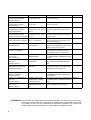
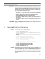
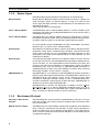
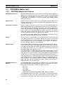
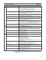
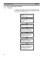
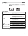
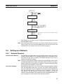
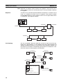
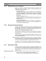
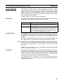
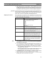
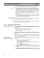
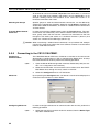
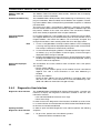
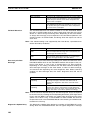
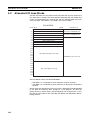
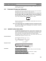
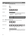
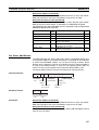
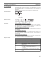
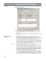
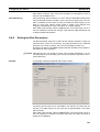
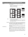
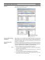
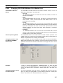
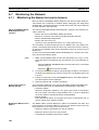
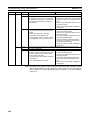
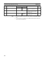
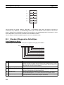
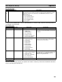
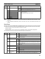
Initial screen
SHIFT
CH
*DM
000000 I/O TBL ?
CHG
000000 I/O TBL
WRIT
????
WRITE
Password
000000CPU BU ST?
0:CLR 1:KEEP
or
(Save or clear the CPU Bus Unit System Setup.)
000000 I/O TBL
WRIT OK
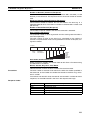
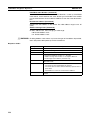
After creating the I/O table, the Unit is ready to be configured for first use on
the PROFIBUS network.
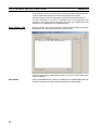
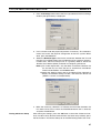
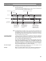
Note After mounting the Unit and starting it up for the first time, the Unit’s Configuration is empty. This will cause the red ERC LED on the front of the Unit to be
switched ON. In this situation, the Unit can still be configured.
2-4
2-4-1
Setting up a Network
Network Structure
Communication Medium
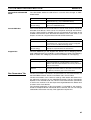
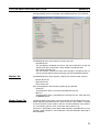
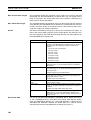
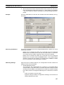
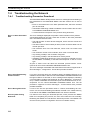
The PROFIBUS standard defines the use of EIA RS-485 as the main communication transport medium. The PROFIBUS Master Unit is designed to interface directly to this type of medium. This section will discuss the setup of
networks based on this medium.
Note The other communication medium specified for PROFIBUS is optical fibre.
The PROFIBUS Master Units does not provide a direct interface to this type of
medium. However, by using third party couplers an interface between EIA RS485 and optical fibre networks can be made.
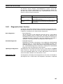
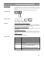
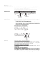
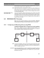
Linear Bus Topology
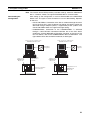
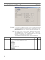
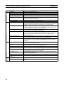
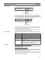
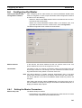
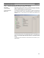
PROFIBUS DP defines the use of the Linear Bus Network Topology. The Bus
must be terminated at both ends, and must not contain network branches.
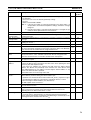
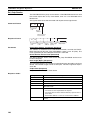
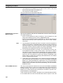
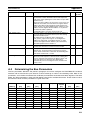
The total cable length of the bus depends on the cable and the selected baud
rate. Also, RS-485 specifies a maximum of up to 32 devices - master and
slave devices - per line segment. If more than 32 devices are to be connected, or if the total length of the segment must be extended beyond its maximum, repeaters must be used to link the separate segments.
37