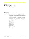
1
RACS R o g e r A c c e s s C o n t r o l S y s t e m Access controller with integrated proximity reader PR201 Version 2.1 Installation and programming manual PR201v2_UK 02-08-12 Introduction The PR301 and PR201 controllers are designed for use in access control systems equipped with electric door lock. The PR301 controller has a built-in proximity reader module and 12 digit keypad, PR201 has proximity reader module only, both controllers have three inputs and tree outputs (one relay output and two transistor outputs). Inputs and outputs of the controller can be configured to several pre-defined functions. The controller can register up to 1000 users, every user can be identify by card or PIN-code or both method at once. The PR301/201 controllers can be programmed locally using MASTER identifier or remotely from the PC. An additional identification terminal (reader) can be connected to controller. Usually an additional identification terminal is used when both side door control is required or when controller unit must be located in protected place in order to avoid access of unauthorized person to controller’s electronics. The PR301/201 controllers can operate is standalone mode or can work in networked system controlled by HOST (PC or CPR control panel). When controllers operate in networked system, access system can deliver few additional features which normally are not available in standalone mode, those feature are: - groups of users, - time zones and schedules, - events recording, - online events monitoring, - and more. Improvements and modifications in version 2.1 The previous versions of PR301/201 have two modes of operation marked OPEN and CLOSED. The names of those modes have been changed in version 2.1, now OPEN mode is called ON and CLOSED mode is marked OFF. Both modes (ON and OFF) are signalized on one dual colored LED marked ON/OFF. When this led is RED it means that controller stay in OFF mode, when is green it means that controller stay in ON mode. In 2.1 version LED OPEN also exists but now it signalize only that door is released. The LED SYSTEM in both versions remains unchanged. The 2.1 version offer few other advantages: reduced current consumption (about 70mA instead of 120mA), new interactive commands which can be send from HOST to controllers, new input type [Input control ON-OFF mode], new input type [Reporting input], which can be declared on every controller input. - Standalone mode of operation When controller operates in standalone mode events recording, users group and time schedules can not be achieved. In this mode access right is granted for all users programmed in controller. Controller programming can be done locally by MASTER identifier or remotely from downloading PC. After programming, controller can autonomically control door. An additional identification terminal with ID=0 can be connected to controller in standalone mode as well. Note: The UT-2 interface is required between PC and controller for downloading. Networked mode of operation When controller operates in networked mode an extra features are available: events recording, access time schedules, remote interactive command from PC, events monitoring, different groups of users. Note: For networked systems the HOST device is required. The PC running continuously with special online software RACS 2.x or CPR access control panel can be a HOST. Networked operation without CPR In this case PC acts as access system HOST, PC must run continuously with special online software RACS 2.x. When PC stop activity (no matter if software error occurred or PC failure) controllers automatically move to standalone mode and continue access control with access rules as they were when failure occurred, we can say that in this case access rules are frozen. After communication with PC is restored all access rules will be refreshed but events which occurred during HOST failure are lost. Note: The RACS 2.x software automatically recognize if access system is equipped with CPR or not, when CPR exists in access system software refuse to run as a HOST. Note: When PC runs as an HOST it should be equipped with emergency supply source e.g. UPS. Networked operation with CPR In this case CPR act as access system HOST, PC is required only for system configuration and events downloading. When computer is connected to access system continuously the online events monitoring and interactive commands are available. During PC online monitoring every events which occurred in system is instantly transferred to computer data base and optionally can be appended to pre-specified *.txt type of files. Such a files can be accessed by customer’s programs for additional operation (e.g. T&A calculations, attendance list etc.). If PC is disconnected from access system or monitoring window is not active the CPR save events in internal buffer. Events buffer can be downloaded by interactive command or is downloaded automatically after monitoring window is activated. 2 PR201v2_UK 02-08-12 Note: For networked systems with CPRs the RACS 3.x software is required. CPR characteristic: 250.000 or 64.000 events buffer (CPR32 or CPR8), operation with 32 or 8 access controllers (CPR32 or CPR8), buffered 2A power supply, battery charging control circuit, automatic battery cut off circuit below 10V level, LED/buzzer signalization panel, PGM alarm output, TAMPER loop input line, metal case with compartment for 17Ah battery. - Building installation above 32 controllers The separate CPR 32/8 control panel can operate with up to 32/8 controllers. When more door have to be controlled the access system with multiply subsystems must be utilized (see diagram). Every subsystem must have its own CPR panel, UT-2 interface, communication bus and must be connected to separate PC’s COM port. Note: Operation with multi subsystems requires RACS 3.x software packet. Recording of events In case where controllers operate in a networked mode, the following types of events can be recorded: • • • • • • • • • • Access granted for … Access deny for … PIN-code under constrain (DURESS ENTRY) by user .... "PREALARM" condition on … „DOOR AJAR” condition on … „FORCED ENTRY” condition on … Controlled switched to ON or OFF mode by … Reporting input no … triggered Reporting input no … returned to normal RESTART of the controller… Operation with remote access terminal One additional access terminal (reader) with ID=0 can be connected to PR301/201 controller. Terminal does not make decision to grant or deny access, terminal reads user identifier (card code, PIN-code or both) than send it to controller which examine codes and grant or deny access for recognized user. There are few types of terminals including outdoor versions. Notice: The roger access terminals (PRT series) utilize clock and data lines for communication with controller but this standard differs from common CLOCK&DATA format utilized by many producers. Some PRT terminals are also offered with Wiegand and Magstrip standards but such a types are specially marked. Optical (LED) signalization LED ON/OFF LED OPEN LED SYSTEM !R " " The controller is in the ON mode. !G " " The controller is in the OFF mode. " " # The controller stands by for entering the MASTER or SWITCHER Ident. " # " The controller stands by for entering the MASTER Ident. #R " " The controller stands by for entering the INSTALLER Ident. " ! ! The controller is in the user programming mode. " # # Standby for entering the remaining part of the command in the user programming mode. !R " ! The controller is in the installer programming mode. #R " # #R # # Standby for entering the remaining part of the command in the installer programming mode. EEPROM memory data damage, the default settings should be restored and the controller should be reprogrammed. #R # ! The controller is being programmed from PC (Downloading process in progress) !R/G ! " The LED’s light up when the door is open. Interpretation. 3 PR201v2_UK 02-08-12 ! - indicator is on " - indicator is off # - indicator pulses !R - indicator is red !G - indicator is green !R/G - indicator is red or green Acoustic signals SYMBOL OF SIGNAL ***** NAME OF SIGNAL MEANING RESTART 1. The signal appears after switching on the power supply. 2. After an exit from programming modes. 3. After internal Watch Dog circuit operation. 1. The programming functions were performed correctly. 2. A valid identifier (code or card) was used. 1. The controller stands by for the remaining part of the command. 1. A programming error. 2. An invalid identifier (code or card). 3. An attempt to program an identifier, which already exists in the reader. 1. An attempt to assign the same functions to the IN1 and IN2 inputs. 1. An identifier (card or code) entry. ***** * * * * * * Etc. O.K. signal Encourage signal Type 1 error signal Type 2 error signal Identifier reading signal Memory error 1. Controller memory data damage – the EEPROM memory should be RESET to the default settings and the reader should be reprogrammed. Users The controller can distinguish the following four types of users: USER TYPE ID NUMBER INSTALLER NONE MASTER 0 SWITCHER Full SWITCHER Limited NORMAL 001..049 050..099 100..999 AUTHORIZATION Authorization for an entry to the installer programming mode, it does not have an identification number. Authorization for an entry to the user programming mode, opening the door and switching the reader between the CLOSED/OPEN conditions. Its identification number is 000. Users with ID = 001..049 have authorization for opening the door and switching the controller between the ON/OFF mode. Users with ID = 050..099 have authorization only for switching the controller between the ON/OFF conditions Authorization only for opening the door. The users of this type have identification numbers from 100 to 999. The controller identifies the users by identifiers (abbrev. Ident.). Each user has his/her own identification number (ID = 000…999). Identifier can be a code or proximity card. In case the [Dual identification mode] option is switched on, the controller requires the use of both forms of identification, i.e. code and card in any sequence. The controller accepts codes consisting from 3 up to 6 digits and cards (proximity transponders) based on the V4001/2 module of EM MICROELECTRONIC – MARIN Switzerland. Note: The PR201 controller can identify users only by cards, the [Dual identification mode] is not available in this model. Transponder module specification: • 64-bit ROM memory, pre-programmed by the manufacturer. • Amplitude modulation ASK (MANCHESTER coded). • Operating frequency 125 kHz. • Transmission speed 2kB/sec. • Note: The term "identifier" or "Ident." means the operation of code entering, card reading or both operations in case the [Dual identification mode] is activated. Examples: 1. [MASTER Ident.] = [MASTER code][#][MASTER card] 2. [MASTER Ident.] = [MASTER code][#] 3. [MASTER Ident.] = [MASTER card] or or In example no. 1. the AND option is on for the MASTER identification of the user. The ON and OFF mode of controllers When controller stay in OFF (red) mode a SWITCH output is not active, when controller is in ON (green) mode the SWITCH output is activated. Generally the SWITCH output is dedicated for integration with alarm system but it can be used for other purposes e.g. to control access to specialized equipment (e.g. copy machine, computer, lighting, heating etc.) 4 PR201v2_UK 02-08-12 Switching between ON and OFF mode The ON/OFF mode can be controlled in few different ways: locally by use of SWITCHER or MASTER identifiers, by external signal connected to input declared as [Input control ON/OFF mode], automatically by ON/OFF mode schedule declared in software, remotely by interactive command from RACS software. Note: The SWITCH output change its state together with ON/OFF mode of controller, all methods of ON/OFF mode control are also the methods of SWITCH output control. Note: When input is declared to function [Input control ON/OFF mode] other methods of ON/OFF mode control are not available. Manual method of ON/OFF control The controller can migrate from the ON to OFF mode and inversely after two consecutive use of the MASTER or SWITCHER identifier. Examples: 1. Enter the MASTER Ident., stand by to the moment the SYSTEM indicator starts pulsing, when the SYSTEM indicator pulses, use the MASTER Ident. again – controller will change from ON into OFF or inversely condition. 2. Enter the SWITCHER (ID=001…049) Ident., stand by to the moment the SYSTEM indicator starts pulsing, when the SYSTEM indicator pulses, use the SWITCHER Ident. again – controller will change from ON into OFF or inversely condition. 3. Enter the SWITCHER (ID=050…099) Ident., once – controller will change from ON into OFF or inversely condition. Opening the door The door can be opened by use of the MASTER, SWITCHER Full (only with ID = 001..049), NORMAL identifiers or pressing the exit button. The door is being opened for interval declared by [Time for entry]. When controllers operate in standalone mode access is normally granted for all users programmed in controller. Note: When the option [Access may be granted only in ON mode] is activated, the access will be granted only if controller stay in ON (green) mode when stay in OFF (red) access will be denied. Switching controller between ON/OFF mode user can temporally enable or disable access to door opening. Alarms The controller is able to recognize and signalize the following alarm conditions: Alarm conditions PREALARM DOOR AJAR FORCED ENTRY Signalization priority The alarm occurs after three consecutive attempts of entering Low an unknown identifier repeated in a period shorter than 1 minute. The alarm occurs after door remains open in a period of time Middle defined by “Time for door closing”. The alarm occurs after door opening without the use of Highest controller. Cause Signalization method on ALARM output Single pulse every 2 seconds. Double pulses every 2 seconds. Pulses sequence 0.5 sec. off 0.5 sec. on Every alarm is signalized on ALARM output and is simultaneously send to system HOST. Signalization of the PREALARM, DOOR AJR and FORCED ENTRY disappears automatically after 3 minutes or can be switched off earlier by using any identifier registered in the controller. Alarm on controller can also be cleared remotely from PC. When the ALARM output has been programmed to signalize more than one alarm condition, only the highest priority alarm is signalized. Duress entry This function is not available in PR201 controller. 5 PR201v2_UK 02-08-12 Using cards for digit programming Because the PR201 is not equipped with keyboard, digit programming is performed by multiply readings of the MASTER or INSTALLER card. In User programming mode programming must be done by MASTER card, in Installer programming mode programming must be done by INSTALLER card. How to enter digit during programming PR201 ? Digit [1] - read MASTER (INSTALLER) card one time then wait until two series of beep occur, the [1] is entered. Digit [2] - read MASTER (INSTALLER) card two times then wait until two series of beep occur, the [2] is entered. . . . Digit [9] - read MASTER (INSTALLER) card nine times then wait until two series of beep occur, the [9] is entered. Digit [0] - read MASTER (INSTALLER) card ten times then wait until two series of beep occur, the [0] is entered. Example 1: R201 is in the User Programming mode (LED OPEN and SYSTEM are on), operator has to add new SWITCHER card with ID = 025 (function: [2] + [0] + [2] + [5] + [card]). • • • • • • • • • • Read MASTER card 2 times ( digit 2 ) Wait until PR201 gives * * * * signal Read MASTER card 10 times ( digit 0 ) Wait until PR201 gives * * * * signal Read MASTER card 2 times ( digit 2 ) Wait until PR201 gives * * * * signal Read MASTER card 5 times ( digit 5 ) Wait until PR201 gives * * * * signal Read new SWITCHER card END Example 2: R201 is in the Installer Programming mode (LED CLOSED and SYSTEM are on), operator has to set output for signaling PREALARM condition (function: [3] + [1]) • • • • • Read INSTALLER card 3 times ( digit 3 ) Wait until PR201 gives * * * * signal Read installer card 1 times ( digit 1 ) Wait until PR201 gives * * * * signal End 6 User Programming Mode In order to enter User Programming mode do the following sequence: • • • • When controller stand in ON or OFF mode, [Enter MASTER ident.] [Wait until LED OPEN start blink] [Enter MASTER ident. again In the user programming mode, you can add/delete the NORMAL and SWITCHER identifiers. From this mode you can also go to the Installer Programming mode for detailed setup. When in the User Programming mode the OPEN and SYSTEM LEDs are on. A particular programming function is activated by giving its number (0,1 .. 9). After activation of the function, the OPEN and SYSTEM LEDs starts blink which means that the controller is performing the function and wait for its completion. The following functions are available: [1] - ADD NORMAL USER [1] + [x] + [y] + [z]+ [Card] x y z = 100..999 ⇒ user ID number [2] - ADD SWITCHER USER [2] + [x] + [y] + [z] + x y z = 001..099 ⇒ user ID number [Card] [3] - DELETE USER XYZ [3] + [x] + [y] + [z] x y z = 001..999 ⇒ user ID number Note: The MASTER and INSTALLER identifiers can not be deleted. [4] – MULTIPLY ADDING OF NORMAL USERS [4] + [card1] + ... + [card n] + [#] Cards should be read within 15 seconds interval. The cards will be programmed in a first found free memory location, the new cards do not delete the users already existing in the memory. [5] – MULTIPLY ADDING OF SWITCHER USERS [5] + [card1] + ... + [card n] + [#] Programming principles are as in function [4]. [6] – DELETES USER WITH ENTERED CARD [6] + [card] Note : The MASTER and INSTALLER identifiers can not be deleted. 02-08-12 PR201v2.1UK.doc 02-08-12 [7] – DELETES ALL NORMAL AND SWITCHER USERS [7] + [7] Note: The MASTER and INSTALLER identifiers remain. [8] – ENTRY TO THE INSTALLER PROGRAMMING MODE Note: After EEPROM memory RESET the MASTER and also performs the function of the INSTALLER identifier (MASTER = INSTALLER). [8] + [INSTALLER card] If [Reprogramming disable] option is activated this function does not work, in order to remove this option EEPROM RESET must be done. [0] – EXIT FROM INSTALLER PROGRAMMING MODE [0] + [0] 8 PR201v2.1UK.doc 02-08-12 Installer Programming mode In the Installer programming mode detailed setup of controller is available. Entry to the installer programming mode can be done only from the User Programming mode by activation of function [8]. After entry to the Installer Programming mode the SYSTEM and CLOSED LED are on. A programming function is activated by giving its number (0, 1 … 9 ). After activation of the function, LEDs starts blink. The following functions are available: [1] - IN1 INPUT FUNCTION [1] + [OPTION] [0] ⇒ Input is not active [1] ⇒ NO / Door open sensor (DC) [2] ⇒ NC / Door open sensor (DC) [3] ⇒ NO / Exit button (DR) [4] ⇒ NC / Exit button (DR) [5] ⇒ NO / Input control ON/OFF mode [6] ⇒ NC / Input control ON/OFF mode Note: The NO type of line is triggered when connected to supply minus. The NC type of line are triggered when disconnected from supply minus. In normal condition the NC line must be shorted to ground. [2] - IN2 INPUT FUNCTION [2] + [OPTION] [0] ⇒ Input is not active [1] ⇒ NO / Door open sensor (DC) [2] ⇒ NC / Door open sensor (DC) [3] ⇒ NO / Exit button (DR) [4] ⇒ NC / Exit button (DR) [5] ⇒ NO / Input control ON/OFF mode [6] ⇒ NC / Input control ON/OFF mode Note: The reader does not allow to select the same functions for more then one input. An attempt to designate the same functions for inputs activates signalization of an error. Note : IN3 can not be programmed. This input is permanent set to [Reporting input] type and can be used only in networked operation mode. [3] - SPECIAL OPTIONS [3] + [OPTION] [0] ⇒ A, B and C options are off. [1] ⇒ A [2] ⇒ B [3] ⇒ A + B [4] ⇒ C [5] ⇒ A + C [6] ⇒ B + C [7] ⇒ A + B + C OPTION A B C MEANING [Re-programming disabled] – This option disable entry to the Installer programming mode. This option can only be deleted by RESET of the EEPROM memory. [Access may be granted only in ON mode] – This option disabled access for all users when controller stay in OFF mode. [Bad card timed lock-out - Reading of card/code is blocked for 3 minutes after three consecutive attempts of entering an unknown card or code repeated in a period shorter than 1 minute. 9 PR201v2.1UK.doc 02-08-12 [4] - EMPTY [5] – FUNCTION OF THE ALARM OUTPUT [5] + [OPTION] [0] ⇒ The ALARM output repeats the ON/OFF condition of the controller (follows SWITCH output) [1] ⇒ The output signalizes the condition : PREALARM [2] ⇒ The output signalizes the condition : DOOR AJAR [3] ⇒ The output signalizes the condition : PREALARM + DOOR AJAR [4] ⇒ The output signalizes the condition : FORCED ENTRY [5] ⇒ The output signalizes the condition : PREALARM + FORCED ENTRY [6] ⇒ The output signalizes the condition : DOOR AJAR + FORCED ENTRY [7] ⇒ The output signalizes the condition : PREALARM + DOOR AJAR + FORCED ENTRY Note : SWITCH output can not be programmed. This output follows the controller ON/OFF mode. When controller stay in ON (green) mode SWITCH output is activated, when controller stay in OFF (red) mode SWITCH output is deactivated. Note: Both ALARM and SWITCH output are open collector type. The maximum voltage connected to outputs can not exceed 30V and maximum current must be less then 150mA. [6] - PROGRAMMING OF OPENING TIME AND TIME FOR CLOSING [6] + [P] + [Q] + [R] + [S] PQ = 01..99 ⇒ [Time for entry] RS = 01..99 ⇒ [Delay before DOOR AJAR alarm] Time for entry specify time interval for which door lock will be activated after access is granted. Delay before door ajar specify time interval in which door should be closed, otherwise DOOR AJAR alarm will be activated. Note : When controller operates with [Door open sensor] the RELAY which activates electric look will be triggered off about 2..3 second after door became open no matter what [Time for entry] is programmed. [7] - PROGRAMMING OF READER IDENTIFICATION NUMBER [7] + [I] + [D] ID = 00..99 ⇒ the reader ID number If the controller is linked with the communication bus and operates under the PR Master software, this number identifies the controller in networked system. All the controllers linked to the communication bus must have different ID numbers. Communication with the controllers with the same ID numbers is not possible. [8] - PROGRAMMING OF INSTALLER IDENTIFIER [8] + [INSTALLER card] The new INSTALLER card is programmed. [9] - PROGRAMMING OF MASTER IDENTIFIER [9] + [MASTER card] The new MASTER card is programmed. 10 PR201v2.1UK.doc 02-08-12 EEPROM RESET – Return to default (factory) settings After EEPROM RESET all existing data in memory are deleted and default values are restored. After EEPROM RESET, operator must program new MASTER identifier. The EEPROM RESET is done in the following way: • • • • press EEPROM RESET pushbutton until LED OPEN starts blink (approx. 6 seconds), release EEPROM RESET button, read the new MASTER card the controller is ready for operation. Note: After the EEPROM RESET, the MASTER identifier also performs the function of the INSTALLER identifier (MASTER = INSTALLER). You can change the INSTALLER identifier in the Installer Programming mode. Default (factory) settings of EEPROM memory Controller identification number (ID) IN1 input IN2 input Reprogramming disable Access may be granted only in ON mode Bad card timed lock-out Time for entry Delay before DOOR AJAR alarm Function of ALARM output ;00 ;NO / Door open sensor (DC) ;NO / Exit button (DR) ;option OFF ;option OFF ;option OFF ;2 seconds ;09 seconds ;PREALARM+DOOR AJAR+FORCED ENTRY Technical data Supply voltage Current consumption (average) Ambient temperature Dimensions Weight ; 10..15Vdc ; 70 mA ; 0..50 C deg. ; 105 X 106 X 31mm ; approx. 165 grams 11 PR201v2.1UK.doc 02-08-12 Installation The controller should be hung near the controlled passage, far from any sources of heat and moisture. Electric connections should be made with the power supply off according to the drawings shown at the end of this manual. After the first time power supply is switched on, the controller wake in OFF (red) mode with pre-programmed MASTER card and default settings. Note: The controller is not fitted for outdoor operation. For outdoor operation the proper additional terminal should be used (e.g. PRT11 or PRT22). Installation recommendations 1. 2. 3. Supply of the controller and electric lock should be done with separate wires. Use at least one 1A power supply unit for each of 4..8 controllers. Do not use large (above 2A) power supply units to supply access control system, instead of it use many smaller power supply units located near the powered controllers. 4. Power supplies should be equipped with battery. 5. Connect all supplies minus together to ground potential. 6. Do not connect supplies plus terminal together. 7. The maximum supply voltage dropout between power supply connectors and any controller should be less than 1.0 Volt. 8. It is recommended to lay the Communication Bus with a twisted pair of wires, such a conductor provides a high resistance to interferences and optimum immunity against disturbances. 9. Install shielded cables only if strong electromagnetic interferences exists, generally shielded cables reduce signal quality. 10. Connect semiconductor diode close to inductive load (door strike or electromagnetic lock), such a diode clamp overvoltages spikes and reduce interferences generated by access control system. 11. When locating controller on metal surface use additional non metal spacers (about 10..20 mm) between controller and rear surface. 12 PRESS EEPROM RESET UNTIL LED OPEN STARTS BLINK (approx. 6 second) DATA ERROR - - - - - etc. NO DATA IN EEPROM MEMORY O.K. ? READ MASTER CARD Entry to the USER PROGRAMING MODE RETURN TO DEFAULT SETTINGS Exit from PROOGRAMMING MODE POWER ON YES RESTART ON/OFF OPEN SYSTEM (ON/OFF IS RED) IDENTIFIER “SWITCHER” ID from 001 to 049 IDENTIFIER “SWITCHER” ID from 050 to 099 IDENTIFIER “MASTER” OFF MODE LED SYSTEM BLINK IDENTIFIER “SWITCHER” ID from 001 to 049 ON/OFF OPEN ON MODE SYSTEM (ON/OFF IS GREEN) Simplified operation flow chart od PR201 controller IDENTIFIER “MASTER” LED OPEN BLINK LED SYSTEM BLINK WAIT IDENTIFIER “MASTER” PR_040_UK_201.cdr Exit from PROOGRAMMING MODE Entry to the USER PROGRAMING MODE ON/OFF OPEN USER PROGRAMMING - SYSTEM ADD “NORMAL” USER [1] + [ x ] + [ y ] + [ z ] + [card] ADD “SWITCHER” USER [2] + [ x ] + [ y ] + [ z ] + [card] [3] + [xyz] DELETE USER NO ... MULTIPLAY ADDING OF ”NORMAL” USERS [4] + [card 1] + ... + [card n] + [#] MULTIPLAY ADDING OF ”SWITCHER” USERS [5] + [card 1] + ... + [card n] + [#] DELETES USERS WITH ENTERED CARD [6] [card] ON/OFF OPEN INSTALLER PROGRAMMING SYSTEM [1] + [OPTION] [2] + [OPTION] EXIT FROM PROGRAMMING MODE [0] + [0] AUTOMATICALLY AFTER 3 MINUTES WHEN NO OPERATION IN 2 INPUT FUNCTION [3] + [OPTION] SPECIAL OPTIONS FUNCTION OF OUTPUT ALARM [5] + [OPTION] PROGRAMMING OF OPENING TIME AND TIME FOR CLOSING [6] + [P] + [Q] + [R] + [S] PROGRAMMING CONTROLLER IDENTIFICATION NUMBER [7] + [ I ] + [ D ] DELETES ALL “NORMAL” AND ”SWITCHER” USERS [7] + [7] ENTRY TO THE “INSTALER’S” PROGRAMMING MODE [8] + [“INSTALLER” card ] IN 1 INPUT FUNCTION PROGRAMMING OF “INSTALLER” IDENTIFIER [8] + [“INSTALLER” card ] PROGRAMMING OF “MASTER” IDENTIFIER [9] + [“MASTER” card ] EXIT FROM PROGRAMMING MODE [0] + [0] AUTOMATICALLY AFTER 3 MINUTES WHEN NO OPERATION THE OPTIONS AVAILABLE IN INSTALLER PROGRAMMING MODE FUNCTIONI [1] ; [2] - OPTION [0] input off [1] NO/Door open sensor (DC) [2] NC/Door open sensor (DC) [3] NO/Exit button (DR) [4] NC/Exit button (DR) [5] NO/Input control ON/OFF mode [6] NC/Input control ON/OFF mode FUNCTION [3] - OPTION [0] A, B and C options are off [1] A [2] B [3] A + B [4] C [5] A + C [6] B + C [7] A + B + C FUNCTION [5] - OPTION [0] The bistable output (repeats ON/OFFmode of the controller) [1] The output signalizes the condition : PREALARM [2] The output signalizes the condition : DOOR OPEN [3] The output signalizes the condition : PREALARM + DOOR OPEN [4] The output signalizes the condition : FORCED ENTRY [5] The output signalizes the condition : PREALARM + FORCED ENTRY [6] The output signalizes the condition : DOOR OPEN + FORCED ENTRY [7] The output signalizes the condition : PREALARM + DOOR OPEN + FORCED ENTRY OPTION A: “Reprograming disable”; The option disabling programing (local or download) of the controller in future.This option can only deleted by RESET of the EEPROM memory. FUNCTION [6] - OPTION [PQ] = 01 ... 99 - time for entry [RS] = 01 ... 99 - delay before DOOR AJAR alarm OPTION B: “Access can be granted only in On mode” - door can only be opened when controller is in the ON mode FUNCTION [7] - OPTION [ID] = 00 ... 99 - the controller ID number OPTION C: “Bad identifier timed lock-out”; Reading of identifier is blocked for 1 minute after three consecutive attem pts of entring an unknown identifier repeated in period shorter than 1 minute. PR_041_UK_201.cdr SHIELD NOTE: use shielded cabels only if strong interferences exists. Comm. Bus Twisted pair of wires recommended. GND + 12V POWER SUPPLY 12Vdc e.g. PS10/20 EEPROM RESET SN220K Controller 4,7k 4,7k 4,7k 33k 33k 33k SUPPLY IN1 IN2 IN3 SHIELD Reporting input, Can be used for any monitoring purpose B A CLOCK DATA TAMPER RXE020 I max =200mA I max =200mA RXE020 MAX 1,5A SN330K ALARM SWITCH NC COM NO 7N220K DATA CLOCK TAMPER PR301/201 Access Controller Arm/Disarm alarm panel(zone) or another equipment control J4 J3 J2 J1 Alarm signalization +12V PRTxx Access Terminal ID=0 Door sensor For external location use PRT22 or PRT11. Exit button Electric lock Electric surge protection diode Installation notes 1. The communication bus length max. 1200m 2. Max. Distance between controller and terminal 300m. 3. The supply voltage reduction between controler (terminal) and power supply should not exceed 1.0V 4. Electric lock should be supplied using separate wires. Typical connection diagram of PR301/201 access controller. PR_033UK.cdr PR_032UK.cdr POWER SUPPLY 12Vdc e.g. PS10/20 GND + 12V CLOCK TAMPER DATA ALARM DOOR NO COM NC SWITCH PRxx1 Access Controller RS 485 A GND + 12 V SHLD B A PR Master DB9 Downloading PR controllers from PC IN 3 IN 2 IN 1 COM 1...COM 4 RS 232 Max 15 m 12 V SHLD UT-2 komputer PC Software PC COMPUTER B MASTER SLAVE POWER PR_036UK.cdr NOTE: GND terminals of each supply units must be connected with additional wire. GND SUPPLY ZONE B A B PR system communication bus - max. length 1000m. Twisted pair of wires without shielding are preffered. Shielded cabels can only be used where strong electric interferences exists. GND POWER SUPPLY B SUPPLY GND 1 2 3 4 5 6 7 8 9 * 0 # 2 3 1 2 3 4 5 6 4 5 6 7 8 9 7 8 9 * 0 # * 0 # B A A SUPPLY B A 1 POWER SUPPLY C SUPPLY ZONE C SUPPLY ZONE D B A A B 1 2 3 4 5 6 7 8 9 * 0 # B 1 2 3 4 5 6 7 8 9 * 0 # GND SUPPLY POWER SUPPLY D SUPPLY A B 1 2 3 4 5 6 7 8 9 * 0 # EARTH Control panel supply zone SUPPLY ZONE E SUPPLY A B A 1 2 3 1 2 3 4 5 6 4 5 6 7 8 9 7 8 9 * 0 # * 0 # A B B 1 2 3 4 5 6 7 8 9 * 0 # 1 2 3 4 5 6 7 8 9 * 0 # GND POWER SUPPLY E B A SUPPLY A B A B 1 2 3 1 2 3 4 5 6 4 5 6 1 2 3 7 8 9 7 8 9 4 5 6 * 0 # * 0 # 7 8 9 * 0 # A B A SUPPLY B POWER SLAVE MASTER SUPPLY UT-2 GND GND SUPPLY A A B On board 2A Power Supply PR MASTER B Access system Control Panel CPR8 or CPR32 PR access control system with 13 controllers, CPR control panel and additional 4 power supply units. PC computer Roger Access Control System structure of access Access Controller system RACS 3.0 CPR Access Control Panel Access Controller COM 8 Access Controller Access Controller Access Controller Access Controller Subsystem G Subsystem F Subsystem B Subsystem E Subsystem A Subsystem D Max 32 Controllers CPR Access Control Panel Access Controller Subsystem C Access Controller Access Controller Access Controller Access Controller UT-2 COM 7 UT-2 COM 6 UT-2 COM 5 UT-2 COM 3 COM 2 COM 4 UT-2 UT-2 UT-2 COM 1 PC computer CPR Access Control Panel Access Controller control RACS 3.0 Access Controller UT-2 The Access Controller Access Controller Subsystem H 1. Every subsystem must be connected to separate COM port via UT-2 interface. 2. Distance between PC and UT-2 may not exceed 15 meters. 3. The UT-2 communication interface as well as CPR control panel can be connected to system communication bus in arbitrary place. 3. Every subsystem must have its own CPR control panel. 4. The maximum length of communication bus must not exceed 1200 meters. 5. System requires RACS 3.0 software pack. Cdr087uk ID selection (valid only for PRT31 terminal) Drilling template 0 1 80mm 2 Optional 60 mm diameter can 3 4 5 6 7 JP1 JP2 JP3 JP4 ON/OFF 80 mm 105 mm OPEN SYSTEM 104 mm Cdr091EN The front and side view of PR201 controller and PRT21 terminal. Scale 1 : 1 16 mm 16 mm