1
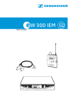
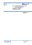
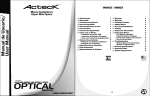
User Guide
miniTX transmitter
The miniTX transmitter is the smallest transmitter in the Audio Ltd range. Designed as a rounded form
to be very easily concealed. All settings can be set and changed via the infra-red port using the
SwitchiR™, and the miniTX can also be turned on and off through clothing using the Control-X.
There are two versions of the transmitter available: one with a 4-pin Lemo connector and the other with
a 3-pin Lemo connector.
Controls, display
and connections
microphones. Position 9 gives maximum gain and each
position decreases the gain by approximately 3 to 4dB,
giving a total of 30dB of adjustment.
Top panel
Audio
input socket
Infra-red
port
Setting up the miniTX
Antenna
To set up the miniTX:
Infra-red port
Receives commands from and transmits status information
back to the SwitchiR infra-red controller, or AudiR for
Palm.
On/Overload
Sleep/Low battery
(red)
(orange)
On/Overload indicator (red)
Flashes on momentarily to indicate an overload in the
presence of a high-level audio signal. At this point, the low
distortion limiter operates.
These steps are explained below:
Fitting the batteries
Open the battery compartment by turning
the battery cover retaining nut in an anticlockwise direction.
Sleep/Low battery indicator (orange)
Rotate the battery cover in either direction.
Flashes every two seconds when the transmitter is in sleep
mode. Remains on when the battery is low.
Insert two AAA (LR03) type batteries as
shown in the diagram on the miniTX sleeve.
Battery compartment
Holds two AAA type 1.5V alkaline batteries.
Close the battery cover and tighten the battery
cover retaining nut in a clockwise direction.
Take care not to over tighten.
Audio input
The miniTX has reverse battery protection.
Allows a microphone or input cable to be connected via
a 4-pin Lemo connector, or 3-pin Lemo connector on an
optional variant.
Low battery indication
SMA socket to which the antenna is connected.
LF cut using SwitchiR
Gives approximately 12dB LF cut at 50Hz, to assist in the
reduction of wind noise.
Gain setting using the SwitchiR
Provides eight gain options when used with standard
–
SMA antenna connector
+
–
M
1
9 K
8 U
0
E in
C e
d
a
+
–
When the battery is low the orange LED will remain on. The
miniTX should not be used when the battery is low as poor
operation may result. A low transmitter battery indicator is
also provided on the DX2040 receiver and on the RK2040
rack.
Note: On the miniTX fitted with the 3-pin Lemo connector,
the transmitter will switch on as soon as the batteries have
been fitted to the transmitter. To maximize battery life the
miniTX should be put into sleep mode by turning the miniTX
off using the SwitchiR.
+
Audio
Infra-red
Antenna
input socket
port
On/Overload
Sleep/Low battery
(red)
(orange)
•Fit the batteries.
•Connect the antenna.
on by plugging in the microphone or input cable
•Switch
(4-pin Lemo version only).
•Check or select the operating frequency.
that the receiver’s no signal indicator is not
•Check
illuminated.
•Check or set the microphone gain.
•Check or set the LF cut filter.
•Check the battery status.
+
Top panel
CHANNEL
User Guide
32
32
miniTX transmitter
the SwitchiR at the infra-red port on the miniTX and
•Point
press OK. If the command was received successfully the
Connecting the antenna
Connect the flexible antenna to the SMA connector.
display will show the new set frequency. For example:
Switching on
FREQUENCY
Insert the microphone plug (only the 4-pin Lemo version
turns on the miniTX).
Fr
Fr
Switching off
Tx
the above steps if an error message is displayed,
•01Repeat
moving the SwitchiR closer to the infra-red port.
Setting the gain
AF LEVEL
AF
TxRx
32
32
•Press MENU followed by
AF LEVEL
A positive microphone bias voltage is provided, enabling the
majority of modern lavalier microphones to be used with
the miniTX.
AF
AF
FREQUENCY
FREQUENCY
Fr
Fr
the front of the SwitchiR with the infra-red port on
•Align
the miniTX and press OK.
TxRx
MHz
MHz
. The display will indicate:
AF LEVEL
AF LEVEL
AF LEVEL
current transmitter gain setting:
AF LEVEL
FREQUENCY
FREQUENCY
Tx
Tx
857.950 2
857.950
2
AF LEVEL
Tx
Tx
•
Press OK. The display will alternately flash between
showing theCHANNEL
frequency and channel number. For
example:
01
CHANNEL
01
Press
to scroll through the 32 frequencies read
or
•from
the transmitter until the desired frequency or channel
is displayed. For example:
CHANNEL
32
AF LEVEL
AF
TxRx
32
CHANNEL
LF Cut
Tx
MHz
MHz
AF LEVEL
To change the gain setting:
2
Error
Error
Press
OK
again. The display will flash the level setting.
•
•
Press
to step between gain settings 2-9 until the
or
required gain setting is displayed. For example:
AF LEVEL
the front of the SwitchiR with the infra-red port
•Align
on the transmitter and press OK. If the command was
receivedAF LEVEL
correctly the display will show the new gain
setting.
For example:
Tx
Tx
9
9
AF LEVEL
9
9
AF LEVEL
Tx
Tx
LF Cut
LF Cut
LFOFF
Cut
Tx
Tx
Tx
Tx
9
AF LEVEL
To change the frequency:
9
Error
Error
Tx
Tx
TxRx
Tx
854.900
854.900
AF LEVEL
AFthe2front of the SwitchiR with the infra-red port
•Align
of the miniTX and press OK. The display will show the
The display shows the current frequency; for example:
FREQUENCY
FREQUENCY
Tx
Error
Tx
MHz
MHz
Tx
TxRx
Selecting the operating frequency
•Press MENU. The display shows:
CHANNEL
CHANNEL
To check the gain setting:
Connect the microphone or input cable to the four-pin Lemo
socket.
Error
9
9
AF LEVEL
Note: On the miniTX gain settings 0, 1, and 2 are the same.
Connecting the audio input
To check the frequency:
9
AF LEVEL
The steps between gain settings 2-9 are approximately 3
to 4dB. Set the gain position so that the Overload indicator
does not flash on during normal operation.
and the transmitter will draw very little current.
You can check or change the operating frequency of the
miniTX via the infra-red control using the SwitchiR.
Tx
01
854.900
854.900
In sleep mode
the orange LED will flash every two seconds
MHz
AF LEVEL
CHANNEL
CHANNEL
To turn the transmitter off remove the Lemo plug (4-pin
Lemo version only), or put the miniTX in sleep mode by
switching it off using the SwitchiR. Alternatively the miniTX
FREQUENCY
can be turned
off or on, even through clothing, using the
Control-X. FREQUENCY
MHz
MHz
Error
Error
MHz
Tx
MHz
Otherwise it will show:
MHz
Tx
857.950
857.950
FREQUENCY
Tx
The red LED
illuminates momentarily under the top cover to
FREQUENCY
indicate that
the transmitter has been turned on.
FREQUENCY
Tx
Tx
CHANNEL
Otherwise the display shows:
Error
the previous steps if an error message is displayed,
•Repeat
moving the SwitchiR closer to the infra-red port.
Tx
Tx
Tx
OFF
OFF
OFF
9
Tx
Tx
Error
User Guide
miniTX transmitter
Infra-red disable
Setting the LF cut filter
The LF cut filter gives an approximately 12dB cut at 50Hz to
reduce handling and wind noise.
You can protect the miniTX from an accidental change
of settings, such as in a live performance, by disabling
the infra-red port on the transmitter. This will prevent all
communication with the transmitter until the the battery is
disconnected and reconnected via the microphone plug.
To check the status of the LF cut filter:
•Press MENU.
•Press a twiceOnuntil the display shows:On
Tx
LF Cut
Error
Disabling the infra-red port
Tx
•Press MENU.
•Press twice. The display will show:
Tx
Tx
Error
the front of the SwitchiR with the infra-red port on
•Align
the transmitter and press OK. The current dISABLE
LF cut filter
Tx
Tx
Ir
?
dISABLE
TxRx
setting is displayed; for example
TxRx
TxRx
•Press OK again. The current setting will flash.
to toggle between ON or OFF until the
or
•Press
BAtt
required setting is displayed.
BAtt
Align
the
front
of
the
Switch
iR
with
•the transmitter and press OK. the infra-red port on
Ir OFF
Tx
Note: Once the infra-red port has been disabled, any
subsequent interrogation of the transmitter will give an
error display; this is not a fault.
TxRx
Sleep mode
If the command was received successfully the new setting
will be displayed. For example:
On
2.6 v
On
On
Otherwise the display will show:
Error
Error
Error
Tx
Tx
The miniTX can be put into sleep mode using the SwitchiR.
In sleep mode the orange LED will flash every two seconds.
The miniTX uses very little current and the SwitchiR can still
be used to read all settings other than frequency.
2.6 v
Tx
dISABLE
dISABLE
is displayed,
•Repeat the previous steps if an error message
dISABLE
When not in use the power should be switched off by
removing the microphone plug or input cable.
TxRx
TxRx
TxRx
TxRx
TxRx
moving the SwitchiR closer to the infra-red
port.
Ir OFF
Tx
TxRx
?
received successfully the display will show:
To change the filter setting:
Tx
Ir
the front of the SwitchiR with the infra-red port
•Align
on the transmitter and press OK. If the command was
OFF
Tx
TxRx
TxRx
Ir
?
IrPutting the?miniTX into sleep mode
Ir Press MENU
• OFF? followed by . The display will indicate:
OFF
OFF
Tx
Checking the battery status
•
•Press
Press MENU.
three times until the display shows:
BAtt
BAtt
BAtt
TxRx
TxRx
the front of the SwitchiR with the infra-red port on
•Align
the transmitter and press OK. The display will show the
TxRx
current battery status:
2.6 v
2.6 v
The battery
2.6level
v can also be checked from the receiver;
Tx
Tx
Tx
see the appropriate instructions for the receiver.
Tx
Tx
Align the front of the SwitchiR with the infra-red port on
Ir OFF
Ir •OFF
the transmitter and press OK. The display will show:
Ir OFFtr oFF
tr oFF
tr oFF
Tx
Tx
Tx
To switch the transmitter on again:
• Press MENU. The display shows:
FREQUENCY
Fr
Fr
Fr
FREQUENCY
MHz
FREQUENCY
Error
Error
Error
MHz
MHz
FREQUENCY
Fr
Fr
Fr
FREQUENCY
MH
FREQUENCY
MH
MH
FREQUENCY
857.950
857.950
857.950
FREQUENCY
Tx
MH
FREQUENCY
Tx
Tx
MH
MH
tr oFF
FREQUENCY
Tx
User Guide
FrOFF
MHz
miniTX transmitter
FREQUENCY
Tx
857.950
FREQUENCY
Fr
MHz
the front of the SwitchiR with the infra-red port on
• Align
the transmitter and press OK. The display shows:
front of the SwitchiR with the infra-red port
• onAlignthethetransmitter
and press OK. The display shows the
current frequency, for example:
tr oFF
Error
FREQUENCY
The red overload LED will flash on momentarily to indicate
that the miniTX has woken from sleep mode.
•
OFF
Press MENU. The display shows:
Tx
MHz
Tx
857.950
MHz
Alternatively, you can use the Control-X to turn the miniTX
on again.
FREQUENCY
Fr
MHz
tr oFF
Technical specification
Error
Frequency range
470MHz–1000MHz
Number of frequencies
32 pre-programmed
Frequency stability
Better than ETS 300–422
FREQUENCY
Up to 24MHz
Switching range
Fr
Output power
MHz
25mW nominal
RF output connector
SMA 50Ω
Audio input connector
4 pin Lemo™
Other variant available: 3 pin Lemo™
System frequency response
50Hz to 18kHz ±1dB
System THD measured at 1kHz
<0.1% at working levels
<0.3% at gain position 9 with
-6dB input in overload
Gain control range
30dB in 8 steps
Maximum input level
0dBu gain position 2
Indicators
Red LED to indicate overload
Flashing orange LED to indicate sleep mode
Static orange LED for low battery
Batteries
2 x AAA (LR03) 1.5V type alkaline
Battery life
Typically 5 hours with alkaline type batteries
Other
miniTX can be switched ON/OFF through clothing via Control-X (available
separately)
Size
16.5 x 82 x 48mm (DxHxW)
Weight
90g inc batteries
Operating temperature
-20°C to +55°C
Compliant to
R&TTE, FCC, EN 300-422 EN 300-445
Error
For further information contact Audio Ltd or your local distributor
www.audioltd.com
User Guide
miniTX transmitter
EC Declaration of Conformity
Déclaration de conformité pour la CEE. EG-Konformitäts-Erklärung
Certificato di conformitá comunitario. Declaración de Conformidad. EG-Conformiteitsverklaring
AUDIO LIMITED. Audio House, Progress Road High, Wycombe, HP12 4JD, U.K.
declare that these devices / déclarons que ces appareils / erklären, dass die Produkte / declaramos que estos aparatos / dichiaria che questi
apparecchi / verklaren, dat deze toestelen
miniTX Pocket Transmitter
conform to the essential requirements of the R&TTE Directive 1999/5/EC. To demonstrate compliance with these requirements, the following
standards were consulted:
sont conformes aux prescriptions fondamentales dan la Directive R&TTE 1999/5/EC. Pour mettre en pratique dans la règle de l’art les
prescriptions,il a été tenu compte des normes suivantes:
den einschlägigen Anforderungen der R&TTE-Direktive 1999/5/EC entsprechen. Zur sachgemäßen Umsetzung der in den EG-Richtlinien
genannten Anforderungen wurden folgende Norman herangezogen:
complen los requimientos básicos de la normativa de la normativa R&TTE 1999/5/EC. Con il fin de realizar de forma adecuada los
requirimientos referidos en la normativa fueron consaltadas las siguientes normativas:
sono conformi alla normativa R&TTE 1999/5/EC. Per un’appropriato risconto nell’ambito della normativa CEE sono state consultate le
seguenti normative:
evereenkomt met de basiseisen van de EG-Richtlijn 1999/5/EC. Om de eisen, die in de EG-Richtlijnen vermeld zijn, in juiste vorm om te
zetten, zijn van volgende normen gebruik gemaakt:
Article 3.1a: EN 60065:2002 (Safety of Electrical Equipment)
Article 3.1b: EN 301 489-9:2002 (Electromagnetic Compatibility)
Article 3.2: EN 300 422-2:2000 (Radio Parameters)
Conformity assessed via Annex IV using a Technical Construction. File examined by Notified Body 0891, TRL Compliance Services Ltd.
Lee Stone, Technical Director. 2007