1
SPR-04
Intelligent
Single Point Sensor
USER MANUAL
by LMI Technologies Inc.
Copyright LMI Technologies Inc.
Version B
1
LMI Technologies Inc.
1673 Cliveden Ave.
Delta, BC V3M 6V5
Telephone: (604) 636-1011
Fax: (604) 516-8368
www.lmint.com
Trademarks and Restrictions
DynaVision is a registered trademark of LMI Technologies Inc.
This product is designated for use solely as a component and as such it does not comply with the standards
relating to laser products specified in U.S. FDA CFR Title 21 Part 1040.
Windows 98, and Windows NT, Windows XP® are registered trademarks of Microsoft Corporation.
No part of this publication may be copied, photocopied, reproduced, transmitted, transcribed, or reduced to any
electronic medium or machine readable form without prior written consent of LMI Technologies Inc.
This product is covered under one or more of the following patents:
USA:
Canada
Germany
5,096.922
5,114.230
5,684.292
4,394.683
1,307.051
30 16 361
Printed in Canada
Version B
2
Copyright LMI Technologies Inc.
Version B
4375,921
5,164.579
5,691.545
5,811.827
1,116.750
31 23 703
4,305.661
5,362.970
5,734.172
4,373.804
5,510.625
4,667.231
Australia
New Zealand
Finland
4,875.776
5,670.787
4,576.482
616.731
228.128
94551
TABLE OF CONTENTS
1.
SPECIFICATIONS
5
1.1 WELCOME TO THE SPR-04
1.1.2 HOW DO LASER TRIANGULATION SENSORS WORK BEST?
1.1.3 MECHANICAL SPECIFICATIONS
ELECTRICAL SPECIFICATIONS
1.1.4.1.
ENVIRONMENTAL SPECIFICATIONS
1.1.4.2.
LASER SPECIFICATIONS
1.1.4.3.
PERFORMANCE SPECIFICATIONS
5
5
5
7
7
7
7
1.
8
LASER SAFETY
2.1 OEM SAFETY RESPONSIBILITIES
2.1.1 LASER WARNING SIGN FORMAT
2.1.2 LASER EMISSION WARNING INDICATORS
2.1.3 BEAM ATTENUATORS
2.1.4 ADDITIONAL REQUIREMENTS FOR CLASS IIIB SENSORS
2.1.5 POWER-ON DELAYS
2.1.6 KEY LOCK SWITCH
2.1.7 REMOTE INTERLOCK CONNECTOR
3.
INTRODUCTION
8
8
9
9
9
9
9
9
10
3.1 HOW CAN THE SPR-04 BE USED?
3.1.1 DO I NEED A COMPUTER TO USE THE SPR-04?
3.2 UNPACKING
3.3 GETTING STARTED
3.3.1 NECESSARY EQUIPMENT
3.3.2 CONNECTOR PIN OUT (AS VIEWED FROM THE SENSOR)
3.3.3 OPERATING YOUR SPR-04 SENSOR IS QUITE SIMPLE.
3.4. MECHANICAL MOUNTING
3.5. SENSOR ORIENTATION
10
10
10
10
10
11
11
12
14
4.
SERIAL COMMUNICATIONS
15
4.1
4.2
4.3
4.4
4.5
GENERAL OVERVIEW
COMMUNICATIONS SPECIFICATIONS
SERIAL SPECIFICATION
SERIAL CONNECTIONS MULTI-DROP CONFIGURATIONS
USING SP SETUP UTILITY
4.5.1. CONNECTING TO THE SENSOR
4.5.2. CONNECTING SUCCESSFULLY TO THE SPR-04 SENSOR
4.5.3. CHANGING SENSOR PARAMETERS
4.5.4. SENSOR SETTINGS/DIAGNOSTIC
15
15
15
16
17
17
18
19
21
5.
COMMUNICATIONS PROTOCOL
25
5.1 GENERAL PACKET PROTOCOL
5.2 PACKET DESCRIPTION
NUMERIC FORMATS
Copyright LMI Technologies Inc.
Version B
25
25
26
iii
TABLE OF CONTENTS
5.6 COMMUNICATIONS ERROR HANDLING
5.6.1 HOW DO I PROCESS A RECEIVED DATA PACKET?
5.6.3 WHAT IF THE SENSOR DETECTS AN ERROR?
5.7 PACKET TIMING
5.7.1 WHAT IF TRANSMISSION TIME BETWEEN 2 BYTES EXCEEDS 50 MS?
5.7.3 HOW DO I MAKE SURE THE HOST AND SENSOR ARE SYNCHRONIZED?
38
38
38
38
38
38
6.
39
APPLICATION PROGRAM DEVELOPMENT
6.1 PSEUDO CODE
39
7.
ANALOG OUTPUT
42
8.
TROUBLESHOOTING
45
8.1
8.3
8.4
8.5
8.6
9.0
LASER IS OFF
NO DATA COMES FROM SENSOR’
S ANALOG OUTPUT.
IN A MULTI-DROP CONFIGURATION,
DATA APPEARS ERRATIC OR JUMPY
DATA IS NOT AS ACCURATE AS EXPECTED
MAINTENANCE
45
45
46
46
46
46
10.
GETTING FURTHER HELP
47
10.1 LIST OF AGENTS
10.1.1 CANADA AND THE UNITED STATES
47
47
iv
Copyright LMI Technologies Inc.
Version B
SPECIFICATIONS
1.
1.1
Specifications
Welcome to the SPR-04
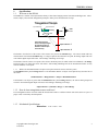
The SPR-04 is a member of the DynaVision family of laser-based ranging sensors from LMI Technologies Inc. These
sensors employ a laser and the triangulation principle to make precise measurements of range.
Triangulation Principle
Object ‘
A’Detected here
Object ‘
B’Detected here
CCD Array
LASER
SPR04
Sensor
Lens
Laser Beam
As the distance from the
sensor to the object changes,
the light from the object is
detected at a different pixel
on the CCD array.
Object at Position ‘
A’
Object at Position ‘
B’
The distance from the face of the sensor to the sensor's zero point is the Standoff range. The sensor cannot make any
measurements closer than the Standoff range. If a target is placed closer than the zero point, the analog output reads zero
volts and the digital output will return “
Out of Range”indicating out of range.
The distance from the sensor's zero point to the sensor's maximum point (for which it has been calibrated) is the Range.
In between these two points the sensor will return a valid reading indicating how far the measurement surface is away
from the standoff, or zero point.
1.1.1
What is the maximum distance an object can be placed from the sensor's reference point?
The Standoff distance plus the Range distance is the maximum distance an object can be placed away from the face of
the sensor.
Standoff distance + Range distance = Object’
s Maximum Distance
If the distance to an object is greater than the Standoff distance plus the Range distance, the sensors analog output will
read zero volts and the digital output will return “
Out of Range”indicating out of range.
Object Distance > (Standoff + Range) => Out of Range
1.1.2
How do laser triangulation sensors work best?
Laser triangulation sensors work best when the measurement surface is a diffuse reflector such as the surface of a piece of
paper, wood, or non-shiny metal and plastic.
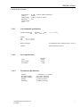
1.1.3
Mechanical Specifications
Dimensions
Copyright LMI Technologies Inc.
Version B
6.00" x 3.06" x 1.64"
5
SPECIFICATIONS
5.000"
4.250"
0.125"
0.691"
3.400"
6.000"
5.750"
5.500"
0.500"
0.280"
1.530"
2.780"
3.060"
0.250"
6
Copyright LMI Technologies Inc.
Version B
1.638"
0.957"
2.307"
SPECIFICATIONS
Electrical Specifications
Power Supply
Voltage
Analog Output
Maximum
Analog Output
Load
1.1.4.1.
15 VDC - 30 VDC (300mA minimum @
15VDC)
0 VDC –10 VDC, 4 - 20mA
5k
Environmental Specifications
Ambient Temperature
max
Operating
min
+50° C (122° F)
0°
C ( 32° F)
Storage
min
-30° C (-22° F)
max
+70° C (158° F)
1.1.4.2.
Relative Humidity
95% Maximum Non-Condensing at 40° C (104° F)
Housing
Gasket aluminum enclosure
Laser Specifications
Class IIIb
Visible
655 nm
< 7 mW
Laser
Wave Length
Laser Power
1.1.4.3.
Performance Specifications
Accuracy
Resolution (Digital):
Resolution (Analog):
Standoff
Max Range
Copyright LMI Technologies Inc.
Version B
+/- 0.005inches (+/- 0.127mm)
0.001 inches (0.025mm)
0.003 inches (0.075mm)
2" (50mm for metric)
8" (200mm for metric)
7
LASER SAFETY
1.
Laser Safety
Caution! Use of controls or adjustments, or performance of procedures other than those specified herein may result in
hazardous radiation exposure.
DynaVision scanners use lasers to illuminate the measurement surface. This requires that specific safety precautions be
taken when working near, or servicing the sensors.
Under the Code of Federal Regulations (CFR) 21, Part 1040, the U.S. Food and Drug Administration (FDA), classifies
the SPR-04 sensor as a Class IIIb device. This classification is clearly marked on the SPR-04 sensor.
Laser
Sensor
Laser
WARNING: DO NOT look directly
into the laser beam
Warning!
The SPR-04 is a Class IIIb laser device. Regardless of the power rating, or whether or not the laser is
visible, the laser should not be viewed directly, or through a mirror, as it may result in damage to the
eyes
2.1 OEM Safety Responsibilities
LMI Technologies Inc. has filed a report with the US Food and Drug Administration (FDA) to assist OEM's in achieving
certification of their own applications by referencing the report accession number. The following paragraphs outline
areas that are not covered by LMI Technologies Inc. submission and need to be specifically addressed by the OEM.
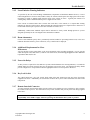
2.1.1
Laser Warning Sign Format
Laser warning signs must be located in the vicinity of the sensors such that they will be readily observed. Refer to the
following diagram for an example of the laser warning sign. Different warning signs are required for different laser
classifications. These are specified in the CFR Title 21, Section 1040. An example is shown below for a Class IIIb
sensor.
D A N G ER
IN VISIBLE AN D /O R VISIBLE LASER R AD IATIO N
AVO ID D IR EC T EXPO SU R E T O B EAM
PEAK PO W ER
W AVELENG TH
50m W
600-780nm
CLASS IIIB LASER PRO DUCT
8
Copyright LMI Technologies Inc.
Version B
LASER SAFETY
2.1.2
Laser Emission Warning Indicators
As specified by the US Food and Drug Administration, Department of Health and Human Services, Code of
Federal Regulations 21 Section 1040 (CFR 21-1040), the controls which operate the single point sensors must
incorporate a visible or audible signal when the lasers of the sensors are active. Typically this consists of a
warning lamp which is illuminated when power is supplied to the sensor.
If the sensors are mounted more than 2 meters from each other, or the controls, it is required that warning
indicators be placed at each location. When mounting the warning indicator it is important not to mount it in a
location that would require exposure to the laser emissions in order to see it.
Additionally, CFR21-1040 standards require that he indicator be clearly visible through protective eyewear
designed specifically for the wavelengths of the emitted laser radiation.
2.1.3
Beam Attenuators
CFR 21-1040 standards specify that a permanently attached method of preventing human access to the laser
radiation other than switches, power connectors, or key control must be employed.
2.1.4
Additional Requirements for Class
IIIb sensors
All Class III laser sensors must adhere to the items mentioned in the preceding paragraphs. For any systems
which incorporate Class IIIb sensors (5mW or non-visible lasers) the following paragraphs describe additional
requirements that must be met.
2.1.5
Power-On Delays
A delay circuit is required for Class IIIb laser systems which illuminates the warning indicators, or sounds the
audible alarms for a short period of time prior to supplying power to the lasers. The length of the delay should
provide enough time to for personnel to take the appropriate action to avoid exposure to the lasers.
2.1.6
Key Lock Switch
The controls must have a key lock switch, which when in the OFF position prevents any power from being
supplied to the lasers. Additionally, the switch must not allow the key to be removed from the lock while in the
ON position.
2.1.7
Remote Interlock Connector
A remote interlock connection that allows remote switches to be attached "in series" with the key lock switch on
the controls must be present. The deactivation of any remote switches must prevent power from being supplied
to the lasers.
None of the items mentioned above are supplied with the SPR-04 and are the
responsibility of the OEM to supply when incorporating the SPR-04 into their system or product.
Copyright LMI Technologies Inc.
Version B
9
INTRODUCTION & INSTALLATION
3.
Introduction
3.1
How can the SPR-04 be used?
The SPR-04 can be used in a wide variety of measurement applications, including:
Object profiling
Thickness measurement
Parts inspection
Object alignment
Range measurement
The SPR-04 is a ‘
smart’sensor incorporating an internal processor to handle calibration, scaling and data
conversion. The SPR-04 provides two analog output (0-10 VDC and 4-20mA) and digital serial output (RS-485).
3.1.1
Do I need a computer to use the
SPR-04?
An SPR-04 with the digital interface can be used with or without a computer control system.
Without a computer
The SPR-04 can be employed as an analog sensor and does not require
connection to an external computer. Connect the cable to:
A suitable power supply
A voltage measurement device
With a computer
3.2
The SPR-04 can be used in a computer-based data acquisition or control system.
Commands requesting data are sent to the sensor and the sensor responds by
providing range values. Commands and data are exchanged with the SPR-04
using a simple serial protocol (see Communications Protocol). To operate the
sensor:
UNPACKING
Upon receipt, unpack and visually inspect the sensor. The sensor is a single metal enclosure with a connector on
one side, and with laser and sensor viewing window on the opposite side. Ensure there is no damage to the
enclosure, connector or view windows.
The enclosed diskette contains:
SPR-04 Utility Program (SPUTIL.EXE)
3.3
GETTING STARTED
3.3.1
Necessary Equipment
10 Copyright LMI Technologies Inc.
Version B
You will need:
a DC power supply
an instrument capable of measuring zero (0) to ten (10) volts DC
a flat surface
Windows 98 or Windows XP (if you are using the sensor with a computer)
an RS-232 to RS-485 converter
INTRODUCTION & INSTALLATION
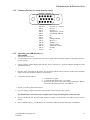
3.3.2
Connector Pin out (As viewed from the sensor)
1
6
15
Pin #1, 15
Pin #2
Pin #3
Pin #4
Pin #5
Pin #6
Pin #7
Pin #8
Pin #9
Pin #10
Pin #11
Pin #12
Pin #13
Pin #14
3.3.3
Power In (15 –30VDC)
Receive (-)
Transmit (-)
Analog Out 0 –10VDC
Out of Range Indicator
NC
NC
Analog Common
Receive (+)
Transmit (+)
Power Common
Analog out 4-20mA
OUT2B
NC
Operating your SPR-04 sensor is
quite simple.
You can use it in two ways
As a stand-alone device requiring only a DC power supply and an instrument capable of measuring zero (0) to
ten (10) volts DC.
Sensors with the optional digital serial interface can be connected to a personal computer through the serial
communication port.
1.
Place the sensor onto a table or flat surface. Be sure that the pathway between the laser window (the round hole)
and the camera (the elongated window) is not obstructed.
2.
Connect the enclosed cable to:
a suitable power supply
a voltage measurement device (e.g. a DVM)
Be sure that the power is OFF on the supply powering the SPR-04,
then connect the cable to the back of the SPR-04
3. Turn on your voltage measurement device.
4. If you are using a computer connect the enclosed cable to the serial port of the computer
The SPR-04 can be connected to both a computer and a voltage-measuring device at the same time.
5.
Do not look directly into the laser output window nor point it in the direction of another person (see Laser
Safety).
6.
Place a suitable target (e.g. a cardboard box or wood block) within the measurement range of the SPR-04
Copyright LMI Technologies Inc.
Version B
11
INTRODUCTION & INSTALLATION
7.
Turn on the power supply to the SPR-04. The SPR-04 does not have a power switch so turning on the power
supply will activate the SPR-04.
8.
If you are using a computer start the SPUtil.EXE application.
Set the software to use the correct communication port (See SPR-04 setup utility). Click on "View " to open the
range and spot information dialog. Click on "Start."
9.
You should now see a voltage reading on the voltage measurement device, and/or a display of the range readings
on the computer screen.
You are now ready to employ the SPR-04 in a wide variety of applications.
3.4.
Mechanical Mounting
The accuracy of the sensor is dependent on a secure mechanical mounting. Any movement or vibration of the
sensor relative to the object being measured will result in measurement errors. The sensor enclosure contains a
mounting plate with three pre-drilled mounting holes (See Figure Below).
Calibration of the SPR-04 is relative to the reference face of the sensor. The minimum distance the target can be
from the reference face of the sensor is the standoff distance.
12 Copyright LMI Technologies Inc.
Version B
INTRODUCTION & INSTALLATION
The surface the sensor is mounted to must be flat within 0.030”(0.76mm) between the three mounting points.
This can be accomplished with 0.125”(3.16mm) standoff washers between the mounting surface and the sensor.
To ensure that the sensor does not report a false reading, it is recommended that a baffle plate be used.
A baffle plate is a solid plate located outside the sensor's measurement range, directly in the sensor's field of
view. There needs to be a 3/8" hole drilled in the plate to allow the laser light to pass through. When there is no
target in the measurement range of the sensor the baffle plate will block the sensor's camera from seeing the laser
light. Therefore guaranteeing a fast response to the target coming into range and going out of range.
Copyright LMI Technologies Inc.
Version B
13
INTRODUCTION & INSTALLATION
3.5.
Sensor Orientation
The sensor should be mounted so the beam is projected perpendicular to the surface.
The surface directly below the sensor should be non-reflective. If material is to move past the sensor, the sensor
should be mounted so that the movement of the material intersects the line between the laser and the camera.
INCORRECT
Material Flow
14 Copyright LMI Technologies Inc.
Version B
Laser radiation is emitted
from this aperture
PEAK POWER 50 mW
WAVELENGTH 600-780 nM
CLASS IIIb LASER PRODUCT
AVOID EXPOSURE
DANGER
INVISIBLE AND/OR VISIBLE LASER RADIATION
AVOID DIRECT EXPOSURE TO BEAM
CORRECT
Material Flow
SERIAL COMMUNICATION COMMANDS
4.
Serial Communications
4.1
General Overview
All communication between the host computer and the sensor is via an RS-485 serial interface.
All commands are initiated from the host computer to the sensor, with the sensor responding to the commands.
4.2
Communications Specifications
The SPR-04 uses the RS-422/485 standard for its serial communication. This is a differential driver/receiver
pair. It is capable of transmitting up to 4000 feet.
The serial ports of most personal computers are based on the two-wire RS-232 standard. To use a personal
computer as the host for a multi-drop configuration, you will need an RS-232 to RS-485 converter box.
The RS-485 option allows the sensor to be used in multi-drop configurations. This means that up to 32 units can
be connected to the same serial line. Each device must have a different address so that you are able to
distinguish which unit you are talking to. The utility SPUtil.EXE is supplied to allow you to set the address of
each SPR-04 unit. This program only works in Microsoft Windows® environments.
4.3
Serial Specification
Transmit and Receive lines are connected to the serial I/O port of a host computer. This serial I/O port must be
configured as follows:
Asynchronous
9600 - 57600 baud.
8 Data Bits
One Stop Bit
No Parity
Copyright LMI Technologies Inc.
Version B
15
SERIAL COMMUNICATION COMMANDS
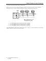
4.4 Serial Connections Multi-Drop Configurations
SPR-04 sensors can be wired in a multi-drop configuration. The serial communication must be wired as full duplex;
meaning four wires are required to complete the hardware connection as illustrated in the figure below:
1ST Sensor
RS-485 to
RS-232
Adapter
Host
Computer
RX
+
RX TX
+
-
TX
-
2ND Sensor
RX
+
RX TX
+
-
TX
-
X Sensor
RX
+
RX TX
+
-
TX
-
TX+
120 ohm
TX-
RS-232 port
RX+
120 ohm
RX-
Up to 32 SPR-04 sensors can
bemulti-dropped as shown.
Tx+ of all the SPR-04 sensors are connected to the Rx+ of the Host
Tx- of all the SPR-04 sensors are connected to the Rx- of the Host
Rx+ of all the SPR-04 sensors are connected to the Tx+ of the Host
Rx- of all the SPR-04 sensors are connected to the Tx- of the Host
A 120 ohm termination resistor must be connected across the Tx+ and Tx- at the end farthest away from the host
computer, and the Rx+ and Rx- nearest the host computer.
16 Copyright LMI Technologies Inc.
Version B
SERIAL COMMUNICATION COMMANDS
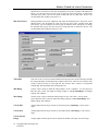
4.5
Using SP Setup Utility
4.5.1.
Connecting to the Sensor
Start the SPUtil.exe software: click on the “
New”button or select the File”Connect”option.
Select the proper COM Port, Baud Rate (57600 - Factory Default Rate), the unit address and click on “
OK”button. If the
unit address is not known, check the”Use global address”option.
NOTE : Do not use ”Use global address”option in multi-drop configuration. All sensors have default address of 1. In
case of multi-drop configuration, ensure that each sensor has been assigned a unique address before being placed on
single communication line.
Copyright LMI Technologies Inc.
Version B
17
SERIAL COMMUNICATION COMMANDS
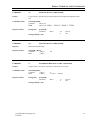
4.5.2.
Connecting Successfully to the SPR-04 Sensor
Serial #.
The number shown here is the sensor’
s serial number which is labeled on the side
of the sensor enclosure (Factory Programmed).
Firmware
This is the firmware version of the sensor (Factory Programmed).
Model #
This is the sensor’
s model number (Factory Programmed).
FPGA
This is the sensor’
s FPGA version of the sensor (Factory Programmed).
18 Copyright LMI Technologies Inc.
Version B
SERIAL COMMUNICATION COMMANDS
4.5.3.
Changing Sensor Parameters
Address
The sensor address may range from 1 to 255, the maximum number of sensors that can be
placed on a multi-drop line. Each sensor must have a different address.
To change the address of the sensor, enter new address and click on “
Address”button.
Note: When changing the address, only one sensor must be communicating with the host.
Baud Rate
This is the sensor’
s Baud Rate that it uses to communicate to the Host. To change Baud Rate
select the Baud Rate from the list and click on “
Baud Rate”button. The Baud rate is preset at
the factory to 57600 Baud.
Error Checking
Error checking method used by sensor to communicate with the Host:
Checksum (Default) or CRC.
To change select the method from the list and click on “
Error Checking”button.
Set to Defaults
Sets all sensor parameters to factory defaults.
Copyright LMI Technologies Inc.
Version B
19
SERIAL COMMUNICATION COMMANDS
Sensor Address
The sensor address may range from 1 to 255, the maximum number of sensors that can be
placed on a single multi drop line. Each sensor must have a different address. To change the
address of the sensor, double click on the current address. New window will appeared, enter
new address and click on “
OK”button.
Note: When changing the address, only one sensor must be communicating with the host.
Baud Rate
This is the sensor’
s Baud Rate that it uses to communicate to the Host. To change Baud Rate
of the sensor, double click on the current Baud Rate. New window will appeared select the
Baud Rate from the list and click on “
OK”button. The available rates are 9600, 19200, 39400,
and 57600.
The factory default Baud Rate is 57600.
20 Copyright LMI Technologies Inc.
Version B
SERIAL COMMUNICATION COMMANDS
4.5.4.
Sensor Settings/Diagnostic
Settings
In the “
Settings”window all sensor settings can be changed accordingly.
Double click on any setting will open SPR04 Settings display.
Copyright LMI Technologies Inc.
Version B
21
SERIAL COMMUNICATION COMMANDS
Max Laser Power
During automatic laser power adjustment, this limits the maximum power. The power can be
adjusted from 1-254: the lower the value, the higher the laser power. Together with “
Min Laser
Power”you can setup the Laser Power range in which the sensor will operate. To change the
maximum laser power, enter the new power setting and click on “
Max Laser Power”
. The
recommended value for Max Laser Power is 2.
Min Laser Power
During automatic laser power adjustment, this limits the minumum power. The power can be
adjusted from 1-254: the higher the value, the lower the laser power. Together with “
Max
Laser Power”you can setup the Laser Power range in which the sensor will operate. To change
the minimum laser power, enter the new power setting and click on “
Min Laser Power”
. The
recommended value for Min Laser Power is 240.
Threshold
This refers to the A to D converted threshold for detecting the laser spot and filtering it through
the background light. The threshold can be adjusted from 0-255. The lower the value the more
sensitive camera becomes to laser light but also becomes more sensitive to background
ambient light. Recommended value for threshold is 48.
Min Range
Sets the sensor’
s range at which the analog output is at the “
volt@min”
. For any range less
than this value, sensor will output the analog reading of “
volt @ OutOfRange”and digital
reading “
Out of Range”
.
Max Range
Sets the sensor’
s range at which the analog output is at the “
volt at max”
. For any range
greater than this value, sensor will output the analog reading of “
volt @ OutOfRange”and
digital reading “
Out of Range”
.
Volt @ Min
Analog output when the object sensed is at the nearest point (“
Min Range”
) of the sensor’
s
range.
Volt @ Max
Analog output when the object sensed is at the furthest point (“
Max Range”
) of the sensor's
range.
Volt @ Out Of
Range
Voltage output when the object sensed is outside the defined “
min range”and “
max range”
.
22 Copyright LMI Technologies Inc.
Version B
SERIAL COMMUNICATION COMMANDS
Hold Last Valid Range
Max # of Dropouts
In case of an out of range reading, the sensor can be setup to output last valid range value for
the next five (5) samples. This is best used to prevent detection of short dropouts or holes when
measuring continuous material. It should NOT be used when trailing edge detection is required
on objects that appear and disappear from view. To change the option check/uncheck the
“
Hold Last Valid Range for ”and then click on “
Enable”button (next to it).
Metric
Changes the sensor mode from Metric to Imperial or Imperial to Metric:
To change select the mode from the list and click on “Mode ”button to put sensor into new
mode.
Note: When changing sensor’
s mode from metric to imperial or vice versa, recheck the
sensor’
s min/max range setting.
Set Sensor
to Defaults
Sets all sensor parameters to defaults:
- use Default button
- use Edit/Set sensor defaults option
Error Checking
Error checking method used by sensor to communicate with the Host:
Checksum (default) or CRC.
To change select the method from the “
Edit”
/”
Error checking method”
.
Copyright LMI Technologies Inc.
Version B
23
SERIAL COMMUNICATION COMMANDS
View Ranges/
Spot Info
Allows user to view range and spot information continuously.
Click on the “
Update Diagnostics”window to continuously display spot Information
.
24 Copyright LMI Technologies Inc.
Version B
SERIAL COMMUNICATION COMMANDS
5.
Communications Protocol
This section describes the contents of the packet used to transmit commands and data between a host computer
and an SPR-04 sensor.
5.1
General Packet Protocol
An asynchronous RS-485 serial communication link serves as the hardware interface between the host and the
sensor(s). The software protocol describes the packet or group of information that is transmitted. This consists
of:
an address
a command
data (optional)
a checksum /CRC
5.2
Packet Description
A packet consists of a string of bytes. The same format is used to transmit from the host to the sensor and back.
PACKET FORMAT
[STX]
1 byte
[STX] [Address] [ Length] [Command] [Data..Data] [Checksum] or [ CRC ]
Start transmission character (02 hex)
[Address]
1 byte
0 broadcast to all sensor addresses.
1..255 addressing a specific sensor.
Note: This byte identifies the sender when received by the host.
[Length]
1 byte
When using Checksum for error checking this is the
number of data bytes from command to the last Data byte (not including the
Checksum). Maximum 255.
When using CRC for error checking this is the number of
data bytes only.
[Command]
1 byte
1..255 See command descriptions.
[Data..Data]
'n' bytes
Number of bytes depend on the command.
[Checksum]
1 byte
data byte.
2's Complement sum of all bytes inclusive of STX and last
2 byte
byte
16 bit CRC of all bytes inclusive of STX and last data
OR
[CRC]
Copyright LMI Technologies Inc.
Version B
25
SERIAL COMMUNICATION COMMANDS
5.3
PACKET EXAMPLE:
To request the current range value from the sensor, the host computer program should send the following message packet:
If using Checksum
02
STX Character
Address
Device Address
1
Command Size
12
Command (read)
Checksum (1Byte)
Address
Device Address
0
Command Size
12
Command (read)
CRC (2 Bytes)
If using CRC
02
STX Character
Numeric Formats
The following describes the format of numbers contained within a packet.
Byte
always an unsigned 8 bit number 0..255.
Words
All words used in commands data streams are signed 16 bit numbers.
When using CRC,MSB of the data word is send first
When using Checksum LSB of the data word is sent first.
Decimal points are assumed depending on data content. For example:
If the data is expected in inches then 1234 would represent 1.234". If the data is expected in
millimeters then 1234 would represent 12.34 mm
26 Copyright LMI Technologies Inc.
Version B
SERIAL COMMUNICATION COMMANDS
5.5
Serial Communication Commands
Command
12
Purpose
Returns the current range reading.
Command Format
[Command]
Command
Response Format
GET_RANGE
(1 Byte)
12
[Command] [Range]
Command
(1 Byte)
Range
(1 Word)
12
Command
18
Purpose
Assigns a specific address to the sensor identified by the serial number. This command can be
broadcasted to all sensors (packet Adders is zero). Each sensor checks the [serial#]
and if it matches the serial # stamped on the face if the sensor, the [address] is set. This
address is then used to send commands to a specific sensor.
Command Format
[Command] [Serial# (8 Bytes)] [Address]
Response Format
if using CRC :
SET SERIAL ADDRESS OF THE SENSOR
[Command]
Command
(Byte)
18
0
Succes
Fail
If using ChkSum : None
Command
132
Purpose
Read the sensor’
s serial address
Command Format:
[command]
Response Format:
[command ] [Address]
Command
(1 Byte)
Address
(1 Byte)
Copyright LMI Technologies Inc.
Version B
GET SERIAL ADDRESS OF THE SENSOR
132
27
SERIAL COMMUNICATION COMMANDS
Command
67
Purpose
Command Format
Set sensor to output last valid (in-Range) reading.
[Command]
Command
(1 Byte)
67
Response Format
if using CRC :
SET_HOLD_SAMPLES
[Command]
Command
(Byte)
67
0
Success
Fail
If using ChkSum : None
Command
68
Purpose
Returns HOLD_SAMPLES value
Command Format
[Command]
Command
Response Format
GET_HOLD_SAMPLES
(1 Byte)
[command ] [hold_samples]
Command
(1 Byte)
Samples
(1 Word)
68
68
Command
36
Purpose
Returns the current reading in inches or metric depending on the sensor mode with offset
added .
Command Format
[Command]
Command
Response Format
SET_SENSOR_MODE
(1 Byte)
[Command] [position]
Command
(1 Byte)
Position
(1 Word)
28 Copyright LMI Technologies Inc.
Version B
36
36
±(sensor range)
SERIAL COMMUNICATION COMMANDS
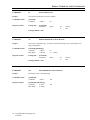
Command
92
Purpose
To put sensors to specific baud to match the RS-485 serial input and output ports baud
rate.
Command Format:
[command] [Baud]
Command
(1Byte) 92
Baud
(1Byte) (0 :
Response Format
if using CRC :
SET BAUD RATE OF THE SENSOR
[Command]
Command
9600, 1 : 19200, 2 : 38400, 3 : 57600)
(Byte)
92
0
Success
Fail
If using ChkSum : None
Command
135
Response
Read Sensors Baud setting
Response Format:
[command ] [Baud]
Command
(1 Byte)
Baud
(1 Byte)
GET BAUD RATE OF THE SENSOR
135
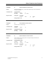
Command
77
Purpose
Change sensor’
s error-check from CRC to Checksum or vice-versa..
Command Format:
[command][Mode]
Command
(1 Byte)
Mode
(1 Byte)
Response Format
if using CRC :
SET ERROR CHENGING TO CRC / CHECKSUM
[Command]
Command
77
0 : CRC / 1 : Chksum
(Byte)
77
0
Success
Fail
If using ChkSum : None
Copyright LMI Technologies Inc.
Version B
29
SERIAL COMMUNICATION COMMANDS
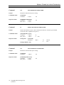
Command
66
Purpose:
Sets all sensor parameters to Factory Defaults.
Command Format:
[command]
Command
Response Format
if using CRC :
SET TO DEFAULTS
(1 Byte)
66
[Command]
Command
(Byte)
66
0
Success
Fail
If using ChkSum : None
Command
93
Purpose
Sets sensor’
s minimum range; for targets closer than this range, sensor will output Out of
range value($FFFF).
Command Format:
[command][Min Range]
Command
(1 Byte)
Min. Range
(1 Word)
Response Format
if using CRC :
WRITE MINIMUM ANALOG RANGE
[Command]
Command
93
( 0 . . 12000 )
(Byte)
93
0
If using ChkSum : None
Command
140
Purpose
Returns the sensor’
s minimum range
Command Format
[Command]
Command
Response Format
GET MINIMUM ANALOG RANGE
( 1Byte )
[Command] [Min. Range]
Command
(1 Byte)
Min. Range
(1 Word)
30 Copyright LMI Technologies Inc.
Version B
140
140
Success
Fail
SERIAL COMMUNICATION COMMANDS
Command
94
Purpose
Sets sensor’
s maximum range; for targets further than this range, sensor will output Out
of range value($FFFF).
Command Format:
[command][Mode]
Command
(1 Byte)
Max. Range
(1 Word)
Response Format
if using CRC :
WRITE MAXIMUM ANALOG RANGE
[Command]
Command
94
( 0 .. 12000 )
(Byte)
94
0
Success
Fail
If using ChkSum : None
Command
141
Purpose
Returns the sensor’
s maximum range
Command Format
[Command]
Command
Response Format
GET MAXIMUM ANALOG RANGE
(1 Byte)
[Command] [Max. Range]
Command
(1 Byte)
Max. Range
(1 Word)
141
141
Command
90
Purpose
Sets the minimum voltage settings. This is the output when target is detected at the
closest point (MIN. Range).
Command Format:
[command][Min_Da_Out]
Command
(1 Byte)
Min_Da_Out
(1 Word)
Response Format
if using CRC :
WRITE MINIMUM ANALOG VALUE
[Command]
Command
90
( 0 . . 9999)
(Byte)
90
0
Success
Fail
If using ChkSum : None
Copyright LMI Technologies Inc.
Version B
31
SERIAL COMMUNICATION COMMANDS
Command
142
Purpose
Returns the minimum voltage setting
Command Format
[Command]
Command
Response Format
GET MINIMUM ANALOG VALUE
(1 Byte)
[Command] [Min DAOut]
Command
(1 Byte)
Min_Da_Out
(1 Word)
142
142
Command
91
Purpose
Sets the maximum voltage settings. This is the output when target is detected at the
Farthest point (MAX. Range).
Command Format:
[command][ Max_Da_Out]
Command
(1 Byte)
Max_Da_Out
(1 Word)
Response Format
if using CRC :
WRITE MAXIMUM ANALOG VALUE
[Command]
Command
91
( 0 . . 9999 )
(Byte)
91
0
If using ChkSum : None
Command
143
Purpose
Returns the maximum voltage setting
Command Format
[Command]
Command
Response Format
GET MAXIMUM ANALOG VALUE
(1 Byte)
[Command] [Max DAOut]
Command
(1 Byte)
Max_Da_Out
(1 Word)
32 Copyright LMI Technologies Inc.
Version B
143
143
Success
Fail
SERIAL COMMUNICATION COMMANDS
Command
146
Purpose
Sets the Out_Of_Range analog value for the sensor. This is the value that sensor outputs
when target is out of the sensor’
s range
WRITE OUT_OF_RANGE ANALOG VALUE
.
Command Format:
Response Format
[command][OutR_Da_Range]
Command
(1 Byte)
OutR_Da_Out
(1 Word)
if using CRC :
[Command]
Command
146
( 0 . . 9999 )
(Byte)
146
0
Success
Fail
If using ChkSum : None
Command
145
Purpose
Returns Out_Of_Range analog value
Command Format
[Command]
Command
Response Format
GET OUT_OF_RANGE ANALOG VALUE
(1 Byte)
[Command] [OutR_Da_Out]
Command
(1 Byte)
OutR_Da_Out (1 Word)
145
145
Command
84
Purpose
Sets the minimum laser power ( This is actually the OFF time of the laser power PWM;
so higher the value , lower the laser power. )
Command Format:
[command][Min_Power]
Command
(1 Byte)
Min_Power
(1 Byte)
Response Format
if using CRC :
WRITE MINIMUM LASER POWER
[Command]
Command
84
( 1. . 254 )
(Byte)
84
0
Success
Fail
If using ChkSum : None
Copyright LMI Technologies Inc.
Version B
33
SERIAL COMMUNICATION COMMANDS
Command
130
Purpose
Returns the minimum laser power setting.
Command Format
[Command]
Command
Response Format
GET MINIMUM LASER POWER
(1 Byte)
[Command] [Min. Power]
Command
(1 Byte)
Min. Power
(1 Byte)
130
130
Command
83
Purpose
Sets the maximum laser power ( This is actually the OFF time of the laser power PWM;
so lower the value , higher the laser power. )
Command Format:
[command][Max_Power]
Command
(1 Byte)
Max_Power
(1 Byte)
Response Format
if using CRC :
WRITE MAXIMUM LASER POWER
[Command]
Command
83
(1 . . 254)
(Byte)
83
0
If using ChkSum : None
Command
129
Purpose
Returns the maximum laser power setting.
Command Format
[Command]
Command
Response Format
GET MAXIMUM LASER POWER
(1 Byte)
[Command] [Max. Power]
Command
(1 Byte)
Max_Power
(1 Byte)
34 Copyright LMI Technologies Inc.
Version B
129
129
Success
Fail
SERIAL COMMUNICATION COMMANDS
Command
82
Purpose
This refers to the A to D converted threshold for detecting the laser spot and filtering it,
lower the value the more sensitive camera becomes.
Command Format:
[command][Threshold]
Command
(1 Byte)
Threshold
(1 Byte)
Response Format
if using CRC :
WRITE THRESHOLD
[Command]
Command
82
( 0 . . 255)
(Byte)
82
0
Success
Fail
If using ChkSum : None
Command
131
Purpose
Returns the threshold value.
Command Format
[Command]
Command
Response Format
GET THRESHOLD
(1 Byte)
131
[Command] [Threshold]
Command
(1 Byte)
Threshold
(1 Byte)
131
Copyright LMI Technologies Inc.
Version B
35
SERIAL COMMUNICATION COMMANDS
Command
134
Purpose
Puts the senor to streaming data mode.
Command Format:
[command]
Command
(1 Byte)
Command
147
END STREAMING
Purpose
Stop the sensor from streaming data mode.
Command Format:
[command]
Command
(1 Byte)
Command
21
GET SPOT
Purpose
Returns a variety of values in relation to current spot
Command Format
[Command]
Command
Response Format
START STREAMING
(1 Byte)
[Command] [Data . . Data]
Command
(1 Byte)
BasePix
(1 Word)
SumPixel
(1 Word)
NumPixel
(1 Word)
SubPix
(1 Word)
Range
(1 Word)
36 Copyright LMI Technologies Inc.
Version B
134
147
21
21
SERIAL COMMUNICATION COMMANDS
5.5.1
Command Summary
Command
12
18
21
36
66
67
68
77
82
83
84
90
91
92
93
94
129
130
131
132
134
135
140
141
142
143
145
146
147
Copyright LMI Technologies Inc.
Version B
Description
Current Position
Set Sensor’
s Serial Address
Read Laser Spot data
Sets Sensor Mode(imperial or metric)
Sets To Defaults
Sets to hold last valid reading
Get last valid reading
CRC / CheckSum mode
Write Threshold
Set Maximum Laser Power
Set Minimum Laser Power
Set Minimum Analog Output value
Set Maximum Analog Output value
Set Sensor’
s Baud Rate
Set Minimum Sensor Range
Set Maximum Sensor Range
Get Maximum Laser Power
Get Minimum Laser Power
Get Threshold
Get sensor’
s serial Address
Start Streaming
Get Baud Rate of the sensor
Get Minimum Sensor Analog Range
Get Maximum Sensor Analog Range
Get Minimum Analog Output value
Get Maximum Analog Output value
Get OutofRange Analog Output
Set OutofRange Analog Output
End Streaming
37
SERIAL COMMUNICATION COMMANDS
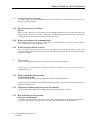
5.6
Communications Error Handling
The validity of the data in all packets transmitted to and from the sensor is checked using the last byte of the
packet as a Checksum or CRC.
5.6.1
How do I process a received data
packet?
When receiving a data packet from the sensor, the host application should verify the validity of the data in the
packet using the Checksum or CRC byte. Additionally, the application should ensure that the command value
returned matches the one sent in the request packet sent to the sensor.
5.6.2
What is the structure of a command packet?
Each command has the same structure as a data packet (see Packet Example). This means you must terminate
each command packet with a Checksum or CRC.
5.6.3
What if the sensor detects an error?
If the sensor detects an error in the transmission it will ignore the command and not respond. If there is no
response from the sensor within 200 ms then the host application should assume an error occurred and retransmit
the original command.
5.7
Packet Timing
Transmissions of packets are initiated by the "STX" (Start of Transmission) character.
Upon receipt of an "STX" character, the sensor will allow a maximum of 50 ms for the next byte to be
transmitted by the host.
5.7.1
What if transmission time between
2 bytes exceeds 50 ms?
The sensor will abort receiving the packet and start looking for another STX character.
Upon receipt of an STX character the host should allow an maximum of 200 ms for the complete response to be
transmitted from the sensor.
5.7.2
What if the complete packet is not received in 200 ms?
The host application should abort the command and start liking for another STX character.
5.7.3
How do I make sure the host and
sensor are synchronized?
To guarantee resynchronization of all sensors on a serial line, the host application should stop all transmissions
for 200 ms. After this time, all sensors on the serial line will be waiting to receive an STX character.
38 Copyright LMI Technologies Inc.
Version B
APPLICATION PROGRAM DEVELOPMENT
6.
Application Program Development
Development of application programs for the SPR-04 is a simple task.
Requirements are:
a suitable serial interface driver
a program that reads requests and receives character data (byte stream) using the Packet Format
described in the previous paragraphs
By writing an application in the host computer, you can:
request data from the sensor
read and process data values returned from the sensor
The Pseudo Code below describes a simple application program for use with a single sensor only. In a multidrop configuration the 'broadcast' address of 0 cannot be used because all sensors would respond simultaneously
to the host, preventing the host from receiving a reliable response.
6.1
Pseudo Code
MainLoop
// We'll talk to any attached sensor so we 'broadcast' to sensor address 0//
// We want to read the range. Which is a command value of 12, and length 1//
WHILE (NOT Finished)
SendSensorCmd(0, 1, 12)
ReadSensorRange
ENDWHILE
// Until we're told to stop//
// Send the sensor our request//
// Read what the sensor sent//
SendSensorCmd(SensorAddress, CmdLength, CmdByte)
XmitBuffer[0] = STX
XmitBuffer[1] = SensorAddress
XmitBuffer[2] = CmdLength
XmitBuffer[3] = CmdByte
// 1st byte is always an STX char//
// the Sensor Address//
If using CheckSum or error checking then
Checksum = (STX + SensorAddress + CmdLength + CmdByte) * -1
XmitBuffer[4] = Checksum
// put it at the end //
else
for (i = 0; i < length[xmitBuffer]; i++)
{
ch = XmitBuffer[i]
for (shifter = 0x80; shifter; shifter >>= 1)
{
flag = (CRC & 0x8000)
CRC <<= 1
CRC |= ((shifter & ch) ? 1 : 0)
if (flag)
CRC ^= 0x1021
}
}
XmitBuffer[4] = CRC (MSB)
Xmitbuffer [5] = CRC (LSB)
Write(XmitBuffer, COMPORT)
StartTimeOutTimer
Copyright LMI Technologies Inc.
Version B
39
APPLICATION PROGRAM DEVELOPMENT
ReadSensorRange
//checksum //
MsgReceivedFlag = FALSE
FirstByteFlag = TRUE
// Initialize status flags//
WHILE ((NOT TimeOut) AND (MsgReceivedFlag = FALSE))
IF ByteRcvd
// Got a byte ?//
IF FirstByteFlag = TRUE
// Yes! Is it the 1st one?//
IF ByteIn = STX
// Yes! Is it an STX ?//
BufferPtr = 0
// Yes! Start storing the packet//
FirstByteFlag = FALSE
RcvBuffer[BufferPtr] = ByteIn
BufferPtr = BufferPtr + 1
ENDIF
ELSE
// We've already got an STX so//
RcvBuffer[BufferPtr] = ByteIn
// add this byte to the queue//
IF BufferPtr = 2
RcvLength = ByteIn + 3
BufferPtr = BufferPtr + 1
ENDIF
ENDIF
// Is this the Length byte?//
// Calc how many bytes we'll get//
// Update our pointer//
//CRC ReadSensorRange //
MsgReceivedFlag
XmitBuffer[4] = CRC = FALSE
WHILE ((NOT TimeOut) AND (MsgReceivedFlag <TRUE))
IF ByteRcvd
IF FirstByteFlag = TRUE
IF ByteIn = STX
FirtsByteFlag = TRUE
BufferPtr = 0
FirstByteFlag = FALSE
RcvBuffer[BufferPtr] = ByteIn
BufferPtr = BufferPtr + 1
ELSE
RcvBuffer[BufferPtr] = ByteIn
IF BufferPtr = 2
RcvLength = ByteIn + 3
BufferPtr = BufferPtr + 1
IF BufferPtr > RcvLength
StopTimeOutTimer
MsgReceivedFlag = TRUE
ENDWHILE
//* Got the Full Message ? *//
//* Yes! Stop the Timeout Timer *//
IF MsgReceivedFlag = TRUE
RcvAddr = RcvBuffer[1]
RcvCmd = RcvBuffer[3]
RcvLen = length[RcvBuffer] –2
RcvCRC/Chksum = Last one or two bytes of RcvBuffer;
40 Copyright LMI Technologies Inc.
Version B
APPLICATION PROGRAM DEVELOPMENT
Calculate CRC or Checksum
IF RcvCRC/CheckSum <> CalcCRC/CheckSum
CRCError = TRUE
ELSE
IF RcvCmd <> CmdByte
CommandError = TRUE
ELSE
SensorRange = WORD(RcvBuffer[4])
ELSE
TimeOutError = TRUE
IF BufferPtr > RcvLength // Got the Full Message ? //
StopTimeOutTimer
// Yes! Stop the Timeout Timer//
MsgReceivedFlag = TRUE
// Set the status flag - We're done//
ENDIF
ENDWHILE
IF MsgReceivedFlag = TRUE
RcvChecksum = 0
RcvAddr = RcvBuffer[1]
RcvCmd = RcvBuffer[3]
// Packet received or Timeout ? //
// Packet received. Then validate it//
FOR loopctr = 0 TO RcvLength
// Calculate the checksum//
RcvChecksum = RcvChecksum + RcvBuffer[loopctr]
IF RcvChecksum <> 0
// Is it valid?//
ChecksumError = TRUE
// No! Indicate the error//
ELSE
IF RcvCmd <> CmdByte
// Yes! Does the response match? //
CommandError = TRUE
// No! Indicate the error//
ELSE
// Otherwise, get the range value//
SensorRange = WORD(RcvBuffer[4])
ENDIF
ENDIF
ELSE
TimeOutError = TRUE
// Too much time passed//
ENDIF
6.2
Reading Streaming Data
When sensor is in the stream mode it continuously sends out range values until host sends any character (byte) to
the sensor to end the streaming mode.
To put sensor into the streaming mode, send command 134 using above described Packet Format
Sensor sends out 16 bit data of the following format:
MSB and LSB
Copyright LMI Technologies Inc.
Version B
41
ANALOG OUTPUT
7.
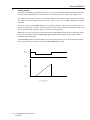
Analog Output
The sensor has an analog range output that starts at zero volts (at the standoff distance) and increases linearly to
ten volts (at the maximum range). Outside the sensor's measurement range the voltage at this output is zero.
The output can source 2mA at ten volts. The internal impedance of the analog output is equivalent to 200 ohms.
The output is protected against short circuits and is able to drive up to a 500pF capacitive load without
oscillation.
The sensor also has an out of range indicator. It is a high low indicator. This is an open collector output. It is
capable of sinking 5mA of current. When the signal is low the target is inside the measurement range of the
sensor. When the signal is high, the target is outside the measurement range.
Note: Since zero volts can represent a target located at the standoff distance from the sensor and ranges outside
the sensor's measurement range, the out of range signal should be used to indicate when a target is inside or
outside the measurement range.
The out of range signal will respond within 0.53ms of the target moving into, or out of the measurement range.
Refer to Figure below to see how the voltage and out of range output respond.
Out of
Range
1
0
10
Analog
output (v)
0
2
5
Range from face of sensor
(inches)
42 Copyright LMI Technologies Inc.
Version B
8
ANALOG OUTPUT
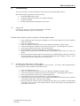
The following example of scanning a flat object with a hole shows the analog and the digital output out of range
with the following settings
Min range
Max range
Volt@min range
Volt@max range
Volt@out of range
Copyright LMI Technologies Inc.
Version B
0”
8”
0 VDC
10 VDC
0 VDC
43
ANALOG OUTPUT
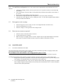
The following example of scanning an object of varying thickness with a hole shows the analog and digital out
of range output with the following settings
Min range
Max range
Volt@min range
Volt@max range
Volt@out of range
44 Copyright LMI Technologies Inc.
Version B
0”
8”
2VDC
10VDC
0 VDC
TROUBLESHOOTING
8.
Troubleshooting
This section will help you with any difficulties you may have in operating the SPR-04 sensor.
Before following the suggestions be sure that you have:
a clean and regulated power source
a calibrated voltage measurement device (DVM/Oscilloscope)
a computer (optional)
clean the camera and laser window glass on the sensor
8.1
Laser is off
Check to see if the power is turned on and providing 15 to 30VDC
Check cabling and ensure power is wired correctly.
No data comes from the sensor’
s serial port. (if using digital output)
1.
2.
3.
4.
5.
6.
7.
8.
8.3
Check cabling and ensure that power and signals are wired correctly. Make sure you have an RS-232
to RS-485 converter.
Check to see that the laser is on
Check to see that the camera's field of view is not obstructed, and that the window is clean.
Connect an LED with a 3.3K ohm resistor in series across Pins #5 - (Out of Range) and #1 (power).
Place a target within the sensor range. The LED should be lit.
Block the path between the camera and the laser. The LED should go out.
Check the analog output with an instrument capable of measuring DC voltage from 0 to 10 VDC (e.g.
DVM).
Move the target back and forth. Observe the analog output. It should change as the target is moved. If
the voltage changes it is likely that your serial port configuration and/or cabling is incorrect. If the
voltage output does NOT change check your wiring again.
No data comes from sensor’
s analog output.
Check cabling and ensure that power and signals are wired correctly. For sensors with the digital interface
option, make sure you have an RS-232 to RS-485 converter.
1.
2.
3.
4.
5.
6.
7.
Check to see that the laser is on.
Check to see that the camera's field of view is not obstructed, and that the window is clean.
Connect an LED with a 3.3K ohm resistor in series across Pins #5 - (Out of Range) and #1 (power).
Place a target within the sensor's range. The LED should be lit.
Block the path between the camera and the laser. The LED should go out.
Connect the serial port of the sensor to a host computer using an RS-232 to RS-485 converter. Run the
test program SPUTIL.EXE. Check the sensor's settings
Move the target back and forth. Observe the displayed range value on your computer. It should change
as the target is moved. If the values change and there is still no analog output, the analog signals are
probably incorrectly wired.
Copyright LMI Technologies Inc.
Version B
45
TROUBLESHOOTING
8.4
In a multi-drop configuration, one or more sensors do not respond and do not provide data to the serial
interface.
1.
2.
3.
4.
5.
8.5
Connect the offending sensor by itself (see previous) to see if it operates correctly in a non multi-drop
environment.
If the sensor behaves correctly in Step #1, the problem may be that the sensor address is not unique, or
it is set to 0.
Be sure you are using an RS-232 to RS-485 converter.
Check that the wiring of the multi-drop configuration is correct (See Serial Connections).
Check that the sensor addresses you are sending are correct. Use the utility program SPUTIL.EXE to
reset any invalid sensor addresses.
Data appears erratic or jumpy
Check for long runs of wire to sensor (excessive wire length can induce electronic noise).
Check for unshielded wires to sensor.
Check for 'voltage' or 'noise' generators near wiring to sensor.
8.6
Data is not as accurate as expected
Check for sources of electronic noise (see above).
Average data in head or in software.
Make sure target is not highly reflective or black. Optical sensors require diffused light to reflect back
to the sensor, too much or too little can cause sensor to be unable to read surfaces correctly.
9.0
MAINTENANCE
9.1
Preventative Maintenance Procedures
Since the DynaVision® scanner heads operate optically, the primary maintenance procedure is keeping the heads, and
especially optical surfaces clean of sawdust, oil and pitch.
Do not immerse the unit in fluids or use a high pressure spray to clean.
The sensor contains optical and electronic components and under no circumstances should the enclosure be opened.
The following maintenance tasks should be preformed regularly to keep the scanner heads in good working order:
Using clean air pressure system blow air over the laser and sensor glass surfaces to prevent dust particles
from settling. It is important that the air be clean and free from oil and water.
It is recommended that the face of the sensor be inspected and cleaned with isopropyl alcohol on a regular
basis. Commercial glass cleaners should not be used; many have chemicals that leave a residue on the glass,
which can affect optical performance.
46 Copyright LMI Technologies Inc.
Version B
GETTING FURTHER HELP
10.
Getting Further Help
If you wish further help on the SPR-04 contact your distributor.
For more information on Safety and Laser classifications, contact:
Center for Devices and Radiological Health, FDA
Office of Compliance (HFZ-305)
Attn: Electronic Product Reports
2098 Gaither Road
Rockville, Maryland 20850
10.1
List of Agents
10.1.1 Canada and the United States
Call our offices at 1-604-940-0141 for the agent nearest you, or visit our web site at www.lmint.com
International
EUROPE
Copyright LMI Technologies Inc.
Version B
LMI Selcom Inc. (Sweden)
Box 250, S-433 25
Ogardesvagen 19 A
Partille, Sweden
ph 46-31-336-25-10
fax 46-31-44-61-79
47