1
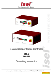
4-Axis-Stepper-Motor-Controller iMC-P Operating Instruction isel Germany AG, D-36124 Eichenzell, Bürgermeister-Ebert-Str. 40 (06659)981-0 (06659)981-776 iMC-P – Operating Instruction All information, technical data and dimensions contained in this booklet correspond to the technical state at the moment of publication. However, possible misprints or mistakes cannot be ruled out. We will appreciate all suggestions for improvement and error notes. We would like to point out that all used software and hardware names of the respective companies generally are subject to protection by brand, trademark and patent law. All rights reserved. It is prohibited to process, duplicate or reproduce this booklet partially or on the whole in any form (print, copy, or other procedure) without written permission of isel Germany AG. This booklet has been translated from the original German version into English language. It does not lay claim to completeness nor flawlessness. In case of doubt the German original has validity. isel controllers are concurrent with CE norms and marked accordingly. Commissioning of all other parts or components, for which CE safety regulations apply, is prohibited until all respective requests are met. isel Germany AG as the manufacturer cannot take over guarantee if you change the controller in any way. The EMC test is valid only for the controller’s original configuration ex works, i.e. the delivery state. Manufacturer: isel Germany AG Bürgermeister-Ebert-Straße 40 D-36124 Eichenzell Tel.: (06659) 981-0 Fax: (06659) 981-776 Email: [email protected] http://www.isel.com Item-no.: 970394 BE001 (translation of operation instruction in german language) Status: 02/2014 Technical specifications subject to change. Up to date Operating instructions and manuals for download you can find here: www.isel-data.de/manuals Table of contents 1 Introduction ....................................................................................................... 4 1.1 Safety symbols ....................................................................................................4 1.2 Safety instructions................................................................................................4 1.3 Intended use ........................................................................................................5 2 Controller types ................................................................................................ 6 3 Technical data ................................................................................................... 7 4 Hardware description ....................................................................................... 9 4.1 Front side iMC-P ..................................................................................................9 4.2 Back side iMC-P ................................................................................................ 11 4.3 Assembly iMC-P ................................................................................................ 17 4.4.1 iMC-P DIP-Switch settings .......................................................................................... 18 5 Operation modes and operation .................................................................... 20 5.1 Controller preparation ........................................................................................ 20 5.2 CNC-mode iMC-P (with Core-module)............................................................... 21 5.3 Initial Operation and user programming in CNC-mode ...................................... 22 5.3.1 5.3.2 Install programming software PALPC.exe ................................................................... 22 PALPC- operation ....................................................................................................... 23 5.4 DNC- mode iMC-P (with Core-Modul)................................................................ 25 5.5 Initial operation und user programming in DNC-mode ....................................... 26 6 EC - Declaration of Conformity ...................................................................... 29 7 Bibliography .................................................................................................... 30 8 Index ................................................................................................................ 30 iMC-P – Operating Instruction 1 Introduction 1.1 Safety symbols You will find different symbols in this manual that signalizes important information/ facts and danger. Warning! This symbol indicates dangers that cause damages for person’s health, physical injury or death. Warning! Dangerous voltage! Warning of danger from electricity. Ignoring can lead to serious injury or death. Attention! This Symbol indicates important notes. Ignoring this symbol leads to damages and malfunctions of the machinery Information: This symbol indicates important information and notes. 1.2 Safety instructions The stepper-motor-controllers iMC-P are designed in conformability to current technical and recognized rules. The device may only be used if it is in correct condition. Any faults have to be eliminated immediately. Neither children nor nonauthorized persons are allowed to put the device into operation. The device may only be used for the intended purpose: control of 2 up to 4 linear or rotational axes with 2-phase stepper motors. All work with the controllers iMC-P, especially initial operation, installation as well as external wiring must be executed by authorized personal regarding electrical industry rules and accident prevention regulations. Assembly and use of operating material has to be according to Machine directive 98/37/EC (valid until 28/12/2009) resp. 2006/42/EC (becomes operative from 29/12/2009) and Low voltage directive 73/23/EWC. In case of in proper use even the observation of the respective rules and standards does not protect against physical damages and damage to property. Do not expose the device to high humidity or high vibrations. Please take care of the instruction manual. Be sure that all users know the instructions. Ignoring the instruction manual can lead to damage, heavy physical damage or to death. page - 4 iMC-P – Operating Instruction 1.3 Intended use The stepper-motor-controller iMC-P is a freely programmable compact control for four linear or rotational units with 2-phase stepper motors. The controller integrates four motor power amplifiers with step/direction interface, a processor core with flash memory to interpret the user programs and generating step/direction signals for the power amplifiers, power supply units, security circuit module and a table housing with net input filter and control elements. The processors operating system (firmware) provides following operation modes: DNC-mode: The controller is permanent connected with a PC/laptop via serial interface. CNC-mode: The controller works „Stand Alone“ after a user program is downloaded to the processors flash memory. Both controllers are able to drive stepper-motors in micro stepping mode. The power amplifiers of the iMC-P generates up to 128 micro-steps per full-step. This allows a smoothly run of the connected motors. An automatic current reduction reduces the power loss in the amplifier and motor. The peak current amounts 4,2A and is adjustable via DIP-switches. With the impulse input it’s possible to control the most important functions (start, stop). Thereby it’s also possible to connect an external control console or a higher ranked control (e.g. PLC). All controllers have to be used only with the compatible motor type. Please read this operation instruction manual carefully before first use of the controller therewith you can: • • • Work safely, fast and effective Keep away danger from persons Use all the power and features of the controller. page - 5 iMC-P – Operating Instruction 2 Controller types The stepper motor controller iMC-P are available in two types. The first type has an intelligent core module which is controlled resp. programmed via RS232 or USB interface (in preparation). Commands in the user program will be processed and inverted to step/direction signals for the stepper motor amplifiers by the core module. Furthermore it’s possible to save a user program for the CNC mode (execution of a program without connected control PC) in the flash memory of the core module. The second type has instead of the core module a step/direction module. This module is used to connect the step/direction inputs of the power amplifiers to a connector (Sub-D-25-pin) in the back side of the controller. By means of this interface different control software are able to drive the stepper motor amplifiers via step/direction signals. iMC-P1 with core-module (Part.-No. 381403 000x1) stepper motor controller iMC-P with core-module as desk device with maximum four integrated stepper motor amplifiers MD24/MD28 Main cable (protection contact plug, IEC-60320 power connector) RS232-communication cable, 9-pin Sub-D (socket) to 9-pin Sub-D (plug) Operating instruction iMC-P2 with step/direction-module (Part.-No. 381404 000x1) 1 stepper motor controller iMC-P with step/direction-module as desk device with maximum four integrated stepper motor amplifiers MD24/MD28 Main cable (protection contact plug, IEC-60320 power connector) Operating instruction x …number of amplifiers, 2 - 4 page - 6 iMC-P – Operating Instruction 3 Technical data iMC-P General data: dimensions (W x H x D): weight: maximum number of axis: safety class: ambient temperature: storage temperature: humidity: 375 x 140 x 260 mm 3 kg 4 IP20 0°C - +50°C -20°C - +65°C maximum 90% not condensing Embedded controller data: controller core: program memory: communication via RS232: stepper motor amplifier: maximum input frequency: 32Bit-RISC processor (embedded controller) 512 Kbyte flash total, 16000 commands storable RS232 (19200 baud, 8 data bit, 1 stop bit, no parity) stepper motor power amplifier MD24 40 kHz (full step) page - 7 iMC-P – Operating Instruction electrical data: power supply voltage: peak current per amplifier: rated current per amplifier: power supply voltage of the amplifiers: automatic current reduction: digital inputs: digital outputs: analog outputs: cover/door control: motor brake on Z-axis: safety data: fuse: software for use with core-module: CNC mode: DNC mode: wide range input 110 - 230VAC 50/60 Hz 4,2 A 3,5 A 48 VDC to 60% 8 x inputs 8 x transistor outputs 24VDC/300 mA 1 x relay output 230V/6A 1 x analog output 0…10V for speed control setting to a frequency inverter yes yes EN ISO 13849-1:2006 category 2, PL c 2 x 6,3A/250V time lag PALPC 2.1, @-format Remote (optional: ProNC) page - 8 iMC-P – Operating Instruction 4 Hardware description 4.1 Front side iMC-P 5 - operation mode switch (key switch) Use this switch to choose between automatic- and setup-mode. In automatic-mode (AUTO) you can only open the cover or safety door of the machine if no axis is in motion and the mounted working spindle is switched off (means that spindle does not turn). In the setup-mode (TEST) you can only open the cover or safety door of the machine if the mounted working spindle is switched off (means that spindle does not turn). You can just move the axes at opened cover or safety door if you press the ACK button. Ensure that in setup-mode (key switch on TEST) only authorized personal operates on the machine. 6 - cover-button Use this button to open the machines cover or safety door. This is possible only if the conditions from point “4 – operation mode switch“ are complied. An enable for opening of the cover or safety door is signalized by a white lighted cover button. page - 9 iMC-P – Operating Instruction 7 - start-button If you press the start button in CNC mode (see chapter: 5.2) a saved user program in the flash memory will be executed. You cannot use the start switch in DNC mode. 8 - fault-lamp The fault lamp indicates an error within the safety circuit. 9 - emergency stop switch Turns off the power supply for the motor power amplifiers and the working spindle in case of any danger. This means dangers for the users health or machine safety. The integrated security circuit is applicable category 2 with PL c according to EN 13849-1. If you push the emergency stop switch the motor power supply will be switched off immediately and any axes motion will be stopped. The main power supply voltage of 115/230VAC lies still on the device, only the motor power supply voltage for the amplifiers is switched off. 10 - power-button Use this button to switch on motor power supply voltage for the motor power amplifiers. Conditions for switch on: - Main power switch on the controller back side is switched on - Emergency stop button is pulled out Be sure that the contacts for external emergency stop switch on the remote connector are bridged! 11 - stop-button If you press the stop button in CNC mode an active user program / axis motion will be stopped. You can continue the execution of the user program by pressing the start button. If you press the stop button in DNC mode an active user program / axis motion will be stopped. To continue the execution of the user program you have to use the controller software (ProNC, Remote). 12 - ACK (ACKnowledge-button) This button has no function on 4-axis-controller MC-P. page - 10 iMC-P – Operating Instruction 4.2 Back side iMC-P iMC-P page - 11 iMC-P – Operating Instruction Stepper-Motor connector – motor axis X-, Y-, Z-, A, Sub-D9-pin socket SubD-9-pin connector for motor modules (CNC axis) Connect / disconnect the Sub-D plug only if the controller is switched off. Ignoring this instruction can lead to damage the motor cable or stepper motor amplifier. pin 1 2 3 4 5 6 7 8 9 description motor phase 2B motor phase 2A motor phase 1B motor phase 1A +24VDC brake (+24VDC/1,8A output with reference potential GND) limit switch 2 (Input +24VDC, if limit switch 2 is not actuated: NC GND limit switch 1 (Input +24VDC, if limit switch 1 is not actuated: NC The connection of a stepper motor with brake is only on the connector of the Z-axis possible. At this jack the switching signal (+24 V to pin 6) for the motor brake is provided. Remote - security circuit interface, 8-pin socket Use this connector to include the controller into a higher ranked security circuit system. Please note that the external power input is only useable if the power button from the controller front is switched off. That will be realized by bridging the pins 1 and 2. pin 1 2 3 4 5 6 7 8 description power button select power button select external power (make contact) +24V DC (external power) external emergency stop channel 1 (brake contact, 11) external emergency stop channel 1 (brake contact, 12) external emergency stop channel 2 (brake contact, 21) external emergency stop channel 2 (brake contact, 22) page - 12 iMC-P – Operating Instruction Use external emergency stop: pin 5 and 6 bridged pin 7 and 8 bridged The length of the connection cable for the external emergency stop button must not more than 5m. Use external power button: pin 1 and 2 bridged connect external power button (make contact) on pin 3 and 4 In case of an emergency stop the +24VDC voltage on pin 4 is no longer available. Impulse - interface impulse control, 8-pin connector Use this connector to integrate the function keys start button, stop button and reset from the controller front side as external signal inputs. pin 1 2 3 4 5 6 7 8 description input external START button (make contact) +24VDC input external STOP button (brake contact) output lamp START button GND output lamp STOP button input length measure switch +24VDC If the external STOP button is not used pins 2 and 3 must be bridged. In case of an emergency stop the +24VDC voltage on pin 2 is no longer available. Input - digital inputs, 8-pin connector The controller has 8 digital user inputs. Use these inputs to connect external devices like sensors, switches or outputs from other devices. All inputs are opto-decoupled. If +24VDC lies on the input a logical HIGH is signalized. Not connected (e.g. switch open) a logical LOW is signalized. Do not short 24VDC reference potential of the controller with GND or case ground. page - 13 iMC-P – Operating Instruction The binary user inputs 1 – 8 must be wired as shown opposite. The load of the controller internal 24V power supply unit amounts on 1-active state 4 mA per input. Output - digital outputs, 8-pin connector The controller has 8 digital user outputs. Use these outputs to connect external devices like relays, or inputs from other devices. The maximum load of each relay output is 24 VDC/300 mA. Do not short 24VDC potential of the controller with GND or case ground. If you have pushed the emergency stop switch all states of the binary user outputs will be maintained and not reset! The binary user output 1 – output 8 must be wired as shown opposite. The transistor outputs (output 1 – 8) can be rated with 300 mA per output. If all outputs are switched (1-active) the maximum load of the internal 24VDC power supply unit is 1, 5 A (ca. 180mA per output). page - 14 iMC-P – Operating Instruction Analog - Out, Sub-D9-pin connector Use this connector to drive an external frequency inverter with the corresponding working spindle via a 0 – 10 V analog output. pin 1 2 3 4 5 6 7 8 9 description +24VDC n.u. n.u. make contact 1(potential free contact) analog 0 ...10V GND n.u. make contact 1(potential free contact) GND Cover - Sub-D9-pin connector This connector is used to integrate a solenoid interlock to the security circuit of the controller. On isel machines the solenoid interlock is realized by a switch of type: SCHMERSAL EX-AZM 170-02ZK-24V (part-no. 577047 0800) Only this type interlocks or interlocks with the same functionality have to be used. pin description 1 2 3 4 5 6 7-9 + coil break contact switch 1.1 (bridge to pin 3 if no safety door is used) switch 1.2 (bridge to pin 2 if no safety door is used switch 2.1 (bridge to pin 5 if no safety door is used switch 2 .2 (bridge to pin 4 if no safety door is used - coil break contact n.u. If no cover or safety door is used the pins 2, 3 and 4, 5 must be bridged. Therefore use the enclosed Sub-D 9-pin plug. If the contacts of the interlock is interrupted (e.g. forcible opening of the hood or remove the jumper, Sub-D) will immediately trigger an emergency stop and turned off the spindle. page - 15 iMC-P – Operating Instruction Spindle - 115/230V output, 3-poles Use this output connector to directly tap a working spindle without speed control. Use the delivered mating connector. Maximum load of the relay output is 230 V AC / 6A. AC-Input - net input module 115/230 VAC, 50 - 60 Hz The net input module consists of net input socket, net filter, fuse holder and net main switch. Connect the controller via delivered net cable to a free receptacle. After that you can switch on the controller with the net main switch. RS232 (PC) – programming interface Communication between iMC-P and control PC is realized via a serial interface (RS232). Use the delivered communication (null modem) cable for connection. A software protocol realizes the faultless transmission of the ASCII characters. Therefore it’s necessary that both systems respect the communication protocol: The connected control PC sends a command which ends with a line end character [CR, char (13)]. The processor unit quits the execution or storing of a command with the quitting signal 0[char (48)] or returns an occurred error with an ASCII character unequal 0. Data transfer parameters: - 19200 baud - 8 data bits - 1 stop bit - no parity page - 16 iMC-P – Operating Instruction 4.3 Assembly iMC-P net input module with net filter, main switch and fuses base board with embedded controller and relays 4 x stepper motor power amplifier MD24 switching power supply input 115/230 VAC output 48VDC, 500W switching power supply input 115/230 VAC output 24VDC, 60W function keys module with switches, buttons in the controller case front security circuit board with safety relays page - 17 iMC-P – Operating Instruction 4.4.1 iMC-P DIP-Switch settings The controller iMC-P has four stepper motor power amplifiers MD24. Settings for rated current, step resolution and current reduction takes place by the DIP-switch on the top side of the amplifiers case. Configuration of the controller should be done before first start-up so that a connected motor will not be damaged because of an incorrect power setting. To configure the step resolution and motor current open the cover and set the jumper on each amplifier as follows (more information /1/ Microstepping Driver MD24/MD28): DIP Switch - MD24 in iMC-P 1: 2: 3: 4: 5: 6: 7: 8: current setting 1 current setting 2 current setting 3 current reduction step resolution 1 step resolution 2 step resolution 3 step resolution 4 Current setting (DIP-switch 1, 2, 3) Use the DIP switches 1, 2 and 3 to set the current of the motor. The following table shows the motor current (RMS) setting for the different switch positions: The factory set of the motor current is 2,03 A (RMS)on all motor power amplifiers. page - 18 iMC-P – Operating Instruction Current reduction (DIP-switch 4) Use the DIP switch 4 to set the automatic current reduction. If the DIP switch is set to ON the automatic current reduction is deactivated. DIP switch in state OFF means that the current is set to 50% of the motor current if the motor standstill. DIP 4 ON OFF current reduction in % 0% reduction (deactivated) 50% reduction If the holding torque is sufficient, the activated automatic current reduction is recommended. Step resolution (DIP-switch 5, 6, 7, 8) Use the DIP switches 5, 6, 7 and 8 to set the step resolution. Setting the factor to a higher value causes a smooth motion of the motor but the maximum reachable velocity will taking down. Also the motor torque will be reduced to 75% in microstep mode. The following table shows the DIP switch settings for the different step resolutions: micro steps 2 4 8 16 32 64 128 5 10 20 25 40 50 100 125 steps/ rev. (1,8 ° motor) 400 800 1600 3200 6400 12800 25600 1000 2000 4000 5000 8000 10000 20000 25000 SW5 OFF ON OFF ON OFF ON OFF ON OFF ON OFF ON OFF ON OFF SW6 ON OFF OFF ON ON OFF OFF ON ON OFF OFF ON ON OFF OFF SW7 ON ON ON OFF OFF OFF OFF ON ON ON ON OFF OFF OFF OFF SW8 ON ON ON ON ON ON ON OFF OFF OFF OFF OFF OFF OFF OFF The Factory set of the step resolution is 800 steps/rev for all motor power amplifiers. page - 19 iMC-P – Operating Instruction 5 Operation modes and operation The processors operating system (firmware processor core) provides the following operation modes: DNC-mode: PC/Laptop is permanent connected to the 4-axis-controller via serial interface Software Remote/ProNC is used to drive the controller CNC-mode: 4-axis-controller executes user programs stand alone without a connected PC/Laptop Software PALPC 2.1 is used for programming and download of user programs into the flash memory of the controller 5.1 Controller preparation Before first startup of the controller please check the scope of delivery. The following parts should be included: 4-axis-stepper-motor-controller iMC-P as desk device Net power supply cable 115/230VAC RS232-communication cable, 9-pin Sub-D (female) to 9-pin Sub-D (female) Bridging connectors Operating instruction If all this parts are included you can begin initial operation. Provide all electrical connections. Connectors - Connect net power supply cable - Connect axis (motors) on the controller back side Configuration - Set DIP-switches / jumper for motor current, step resolution, current reduction, motor brakeq (see chapter Fehler! Verweisquelle konnte nicht gefunden werden. and 4.4.1 ) Initial operation - Switch on controller with main power switch on the back side - Check if emergency switch is pulled out - Push power button on the front of the controller Power button should be lighted green – controller is ready for work Operation mode - Use the 4-axis-controller in CNC- or DNC-mode page - 20 iMC-P – Operating Instruction 5.2 CNC-mode iMC-P (with Core-module) The CNC mode (automatic mode = CNC mode) is the program controlled mode of the 4-axis-stepper-motor-controller iMC-P. That means that a user program which is saved in the controller’s memory (flash) will be executed till the end. During the automatic mode (CNC mode) you can stop the execution of the active user program by pressing the STOP-key on front side of the controller or by using the external Stop input. A following operation of the START-key on the front side of the controller or the activation (1-active) of the external start input effects the resumption of the automatic mode. With motor cable connected axis (linear or rotation axis) will be driven by user program commands Binary inputs connected to the input port will be interpreted. Binary outputs connected to the output port will be set/reset by user program. page - 21 iMC-P – Operating Instruction 5.3 Initial Operation and user programming in CNC-mode Creating user programs for 4-axis-controller iMC-P is realized with the software PALPC.exe. The implementation method is simple and described in “/2/ PAL-PC programming instruction“: Analyze technological problem definition: Layout program algorithm (solve problem definition) Implementation of the control algorithm into a PALPC source program *.ppc; edit code with text editor Compile PALPC source file with PALPC compiler; on faultless translation an output file *.out is created by the compiler Download output file *.out into the flash memory of 1-axis-controller MC1 Start program and check control behavior regarding technological problem definition 5.3.1 Install programming software PALPC.exe To install PALPC software do the following: 1. Insert PALPC 2.1 installation medium (delivered CD or USB stick) with the control computer. 2. Following Auto-start-window will be shown (when installing from CD): If Auto-Start-window is not shown start the Windows Explorer and open the root directory of the CD/DVD- or USB-drive. Double click on the file “Autorun.exe“. page - 22 iMC-P – Operating Instruction 3. Click on “Install PAL PC” and follow the installation instructions. PALPC installation assistant installation dialog: 4. Start PALPC.exe via start menu entry or desktop shortcut. On first startup an activation window will be shown. Enter delivered registration data (serial number and activation code) into the dialogs edit fields. 5.3.2 PALPC- operation The use of PALPC and user programming are described in /1/ PALPC user manual and /2/ PALPC programming instruction. For 4-axis-controller iMC-P note following specialties: page - 23 iMC-P – Operating Instruction 1. The declaration #control IMC4; defines target controller as IMC4 compatible controller like 4-axis-controller iMC-P 2. The declaration #axis xyza; defines the axis that will be used, in this case four axis: x, y, z and a 3. The declaration #steps 800; defines the step resolution set by DIP switch e.g. #steps 800; /4 micro steps per full step * 200 full steps/motor revolution 4. The declaration defines the spindle elevation of the connected linear axis, e.g. #elev 5,5,5,4 /elevation 5mm for xyz-axis, 4mm for a-axis #elev 360°/ transmission ratio; defines the transmission ratio of the connected rotary axis, e.g. ZR20 with transmission ratio 1:20: 360 18 #elev 18; 20 page - 24 iMC-P – Operating Instruction 5.4 DNC- mode iMC-P (with Core-Modul) In DNC mode the 4-axis-controller controller iMC-P with core-module is connected permanently via RS-232 interface with a control PC (IBM compatible PC or Notebook). A user program stored in flash memory will not be executed. The commands to execute an action/motion (e.g. reference motion, motion of the axis or I/O actions) will be sent by user software from the PC with the new Remote/ProNC motion control for 4-axis-controller (IMC4 compatibility mode). Necessary COM interface on PC: 9-pin Sub-D (male) COM interface on controller: 9-pin Sub-D (male), labeled with „RS-232 (PC)“ serial interface cable: 9-pin Sub-D (female) to 9-pin Sub-D (female) is within the scope of delivery Image: serial connection (RS-232) between PC / Notebook and iMC-P via interface cable Likewise in this configuration can be done: PALPC 2.1 user program download into the flash memory of the 4-axis-controller iMC-P. (COM Interface for PALPC: 19200 Bit/sec, PalPC.exe) page - 25 iMC-P – Operating Instruction 5.5 Initial operation und user programming in DNC-mode User programming and control of the 4-axis-controller iMC-P in DNC-mode takes place by the programs Remote or ProNC by binding the corresponding motioncontrol-DLL file. Commands in the user program will be send to the 4-axis-controller. Installation of the control software Remote Do the following steps to install setup software: 1. Insert Remote installation medium (delivered CD or USB stick) with the control computer. 2. An Auto-start-window will be shown (when installing from CD): If Auto-Start-window is not shown start the Windows Explorer and open the root directory of the CD/DVD- or USB-drive. Double click on the file “Autorun.exe“. 3. Click on the entry “Installation of Remote“. Choose your language and follow the instructions of the setup assistant. page - 26 iMC-P – Operating Instruction 4. Mark on setup window “Select control“ the option “Stepper motor control IMC4“ to install the IMC4 stepper motor driver module. After finishing the installation click on button “Exit“ to close the Auto-Start-menu. 5. Open the control software Remote via shortcut on the windows desktop or the start menu entry: Start Programs CNCworkbench Remote 6. On first startup of the software Remote you have to type in a serial number and an activation code. You will find this information on the delivered registration formular. Click on button „Next“ to check the registration data. If the data is ok Remote will starting. page - 27 iMC-P – Operating Instruction Use of the controller iMC-P with Remote Using iMC-P (with Core module) with Remote via serial interface: 1. Start control software Remote. If you don’t have activated Remote you have to do it now. 2. After installation of Remote for a specific control (in this case IMC4) all module DLL’s for the motion control, I/O module, spindle module and security circuit module are set correctly. You only have to set the parameters to your machine configuration. Click in the main menu to the entry Settings Control The dialog shows all active and used modules in a list. Mark the line “Motion Control” and click on button “Setup” on the right side to show the settings for communication and axis kinematics. Over the different register cards you can change the parameters like axis direction, spindle gradient, gear etc. for each separate axis. Over the register card “Data transmission” you can change the used COM Port of the control computer. 3. If you have set all parameters close the dialog with the button „OK“. Click on button “Close & Initialize” in the “Control module and settings” dialog to take effect the new settings and reinitialize the control. 4. Perform a software reset and a reference run behaviour of the machine /system. to check correct Additional information to configure Remote you can find in the online help (menu help, F1 key). page - 28 6 EC - Declaration of Conformity Der Hersteller The manufacturer isel Germany AG Bürgermeister-Ebert-Str. 40 D-36124 Eichenzell erklärt hiermit, dass folgendes Produkt hereby declares that the following product Geräteart: 4-Achs-Schrittmotor-Controller Device: 4-axis-stepper-motor-controller Typ: iMC-P Type: Art.-Nr.: iMC-P: 381403 000x, 381404 000x Product - No.: mit den Vorschriften folgender Europäischer Richtlinien übereinstimmt: complies with the requirements of the European Directives: EG-Richtlinie 2004/108/EG EMV Richtlinie EC-Directive 2004/108/EC EMC directive EG-Richtlinie 73/23/EWG Niederspannungsrichtlinie EC-Directive 73/23/ECC low voltage directive Folgende harmonisierte Normen wurden angewandt: Following harmonized standards have been applied: EN 61000-6-2:2005 EMV - Fachgrundnorm - Störfestigkeit für Industriebereich EMC - Generic standards - Immunity for industrial environments EN 61000-4-2:2007 EMV - Prüf- und Messverfahren - Prüfung der Störfestigkeit gegen Entladung statischer Elektrizität (ESD) EMC - Testing and measurement techniques; Electrostatic discharge immunity test EN 61000-4-4:2004 EMV - Prüf- und Messverfahren - Prüfung der Störfestigkeit gegen schnelle transiente elektrische Störgrößen (Burst) EMC - Testing and measurement techniques - Electrical fast transient/burst immunity test EN 61000-4-5:2006 EMV - Prüf- und Messverfahren - Prüfung der Störfestigkeit gegen energiereiche Impulse (Surge) EMC - Testing and measurement techniques - Surge immunity test EN 61000-4-11:2004 EMV - Prüf- und Messverfahren - Prüfung der Störfestigkeit gegen Spannungs-einbrüche / Spannungsunterbrechungen EMC - Testing and measurement techniques - Voltage dips, short interruptions and voltage variations immunity tests EN 61000-6-4:2007 EMV - Fachgrundnorm - Störaussendung Industriebereich EMC - Generic standards - Emission standard for industrial environments DIN EN 55011:2007 Industrielle, wissenschaftliche und medizinische Hochfrequenzgeräte (ISMGeräte) - Funkstörungen - Grenzwerte und Messverfahren Industrial scientific and medical (ISM) radio-frequency equipment - Electromagnetic disturbance characteristics - Limits and methods of measurement Dermbach, 02.08.2009 __________________________________ Hugo Isert, Vorstandsvorsitzender / chairman 7 Bibliography /1/ Microstepping Driver MD24/MD28, Hardware Description, 02/2009 /2/ PAL PC 2.0 Operating instruction, status 06/2004 /4/ ProNC Operating instruction, status 2003 Operating instructions and manuals for download you can find here: www.isel-data.de/manuals 8 Index # #control 26 #steps 26 A installation dialog 25 intended use 4 Interface cable 27 interface impulse control 13 L Low voltage directive 4 ACK 10 activation code 25 Analog - Out 15 O C CNC mode 8, 23 core modul 6 Cover 15 current reduction 21 current setting 20 Operation mode switch 9 output file 24 P D digital inputs 8 digital outputs 8 DNC mode 8 DNC-mode 27 PALPC compiler 24 PALPC.exe 24 peak current 8 power-button 10 program memory 7 ProNC 27 R E rated current 8 Remote 27 RS232 16 emergency stop switch 10 external emergency stop 13 S F flash memory 27 H security circuit interface 12 serial number 25 Spindle 15 start-button 10 step resolution 21 stop-button 10 harmonized standards 31 T I input frequency 7 text editor 24