1
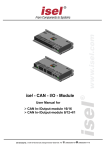
isel – CNC-Joystick User Manual for isel CNC-Joystick isel Germany AG, D-36124 Eichenzell, Bürgermeister-Ebert-Str. 40 (06659)981-0 (06659)981-776 About this manual: The information, technical data and dimensions contained in this print have been up-todate when published. Any eventually existing misprints and mistakes cannot be excluded however. We are thankful for any suggestion for improvement and indication of mistakes. Please note that the used software- and hardware descriptions of each individual company are generally subject to protection of trademarks and patent law. All rights reserved. It is not permitted to reproduce or electronically process, duplicate or spread any part of our prints in any way (print, copy etc.) without written permission of iselautomation. Manufacturer: isel Germany AG Bürgermeister-Ebert-Straße 40 D-36124 Eichenzell Tel.: (06659) 981-0 Fax: (06659) 981-776 Email: [email protected] http://www.isel.com Part.-No.: 970359 BE008 Status: 08/2008 CB Contents 1 Introduction ......................................................................................................... 1 1.1 2 Description of the CNC-Joystick ....................................................................... 1 2.1 3 4 Preamble ...................................................................................................... 1 Specifications ............................................................................................... 1 Connections and plug allocation ...................................................................... 2 3.1 Integration in the security circuit (SK-Modul SKM-S1.2-E) ........................... 2 3.2 Integration in the security circuit of external controller .................................. 2 3.3 Function keys ............................................................................................... 3 Operating ............................................................................................................. 4 4.1 Integration in the graphical user interface (ProNC, Remote) ....................... 4 4.2 Joytick functions ........................................................................................... 7 4.2.1 Joystick buttons and switches 7 4.2.2 Activating the Joystick 7 4.2.3 Moving the axis 8 4.2.4 Changing Step Widths and Override 9 4.2.5 Special functions 9 isel- CNC- Joystick- user manual 1 Introduction 1.1 Preamble isel® has been known for many years for its driving systems and CNC controls with stepper and servo motors. The isel-CNC-Joystick is the ideal supplement for controlling isel – machines. He has a robust and ergonomic molded plastic case. Up to four axes can be used with the joystick. He has a middle position and eight movement directions. Furthermore wear free mechanical contact elements are put into action. The integrated LC-Display shows axis positions, incremental widths and the current Override value. It is no more necessary to observe the graphic surface of the control program when moving to machine axis to new positions. For the connection of the CNC-Joystick to the control cabinet a special connector can be used. Furthermore all important and security-relevant control elements are integrated as buttons or switches. 2 Description of the CNC-Joystick 2.1 Specifications - Data transfer via USB - bus without special software drivers Maximum 4 axes controlable 8 movement directions per plane automatic replacement to mid position when unleashed wear free mechanical contact elements integrated switch for continious and stepwise movement of the axes defined step widths and override adjustable over the joystick well readable LC-Display Power supply voltage +5V over USB bus emergency stop, cover and acknowledge buttons integrated Page - 1 isel- CNC- Joystick- user manual 3 Connections and plug allocation 3.1 Integration in the security circuit (SK-Modul SKM-S1.2-E) The integration in the security circuit takes place over a connection with the security circle module in the control cabinet. The CNC-Joystick is plugged with a connector at the end of the spiral cable to the connection socket intended for it at the front of the control cabinet. The wires of the connection socket are connected with the security circuit module and the USB – bus of the control PC. You find the cable allocation in the wiring diagrams. Note: As soon as the CNC-Joystick is connected, the ACK-button of the joystick can only be used. That means the function key ACK at the Control panel is inactive. 3.2 Integration in the security circuit of external controller CNC Joystick + Adapter Box for external CNC Controller Part-Nr. 359009 Phoenix contact, 6-pins Pin 1-2 3-4 5 -6 Description Emergency-Stop Channel 1 (break contact, Input) Emergency-Stop Channel 1 (break contact, Input) ext. POWER ON (make contact, Input) Function Connection for an external safety circuit (emergency stop switch) Connection for an external safety circuit (emergency stop switch) This contact is switched parallel to the ON button in the controller front. Use this button to switch on the power supply. Page - 2 isel- CNC- Joystick- user manual Note The function of the right button on the CNC joystick case is different from the manuals description. The button is configured as a POWER ON button!!! Connection Adapter Box – Stepper Motor-Controller C142-4 X3 6-pin - Remote connector 3-4 - ext. Emergency stop, 1-channel 5-6 - ext. POWER ON ------- 6-polig Phoenix, Adapter Box 3-4 - Emergency stop, channel 1 5-6 - POWER ON Connection Adapter Box – Servo Motor-Controller CV Serie 10-pin Remote connector 3-4 - ext. Emergency stop, 2-channels 5-6 - ext. Emergency stop, 2-channels 7-8 - ext. POWER ON ---------- 6-polig Phoenix, Adapter Box 1-2 - Emergency stop, channel 1 3-4 - Emergency stop, channel 2 5-6 - POWER ON 3.3 Function keys Emergency stop Turn off the power supply for power amplifiers, inverter and work spindle. ACK (acknowledge) button This button must be pressed so that the axis can be moved in the TEST-mode with opened cover. Cover-button This button is used (if present) to open the cover of the machine. The cover can only be opened if the COVER button is illuminated. This is the case, if all axes are in the home position or the operating mode is switched to test mode. Page - 3 isel- CNC- Joystick- user manual 4 Operating 4.1 Integration in the graphical user interface (ProNC, Remote) The integration of the CNC-Joystick takes place over one 8 bits wide input port. To activate this port, you must bound the Joystick interface- DLL into the Input-/Output modules. Normally one I/O-module is already used in the control environment. Therefore select, for example, the path to the Dll and initialization file for the IO - module 2. Interface DLL and initialisation file are normally in the directory: {appPath}CNCworkbench\Control\IO\UsbJoystick Proceed as follows to get the CNC-Joystick in the module management: Choose an IO modul in the tree view, which is not in use and name it , meaningful with "Usb Joystick." Click on the button “>>“ beside the edit field "Module DLL". Choose "UsbJoystick.DLL" in the directory "\CNCWorkbench\Control\IO\UsbJoystick". The Edit field "Modul initialisation file" shows automatically the “CNCWorkbench\Control\IO\UsbJoystick\UsbJoystick.ini" file. You needn’t to rename the file name. Page - 4 isel- CNC- Joystick- user manual Now click on the button, "Setup"( if nothing should happen, please mark shortly another IO module in the tree view and afterwards again the IO-module for IOUSB). Open the Setup-Dialog through click on the button "Setup". If USB devices where found, they will be shown in the list field with information to serial number, product ID, type. If no USB device where found the list field is empty. Hint: Please note, that only those devices are shown which were connected to the USBbus before starting the software (ProNC/Remote). Now you must only assign the USB Joystick-Device to the Modul-DLL. Choose the device in the list field. Click on “OK“ to save the settings and close the dialog. To check the settings for these Modul-DLL click on “Setup“. The Setup-Dialog will be shown again: The USB device you have selected has an yellow background colour. That means that the Modul-DLL with the device was correctly initialized. Keep in mind that assignment from more than one module DLL to one USB-Device can result an undefined state. Page - 5 isel- CNC- Joystick- user manual Setting inside the Control-Administration To get access to the USB Joystick inside the Control-Administration one setting in the top level must be change. Open the "Extended settings-IO" - Dialog as follows. Highlight in the tree structure "IO modules". Click on "Extended settings" on the right side. You can see following dialog: The available IO modules will be shown in the upper part of the dialog window. Mark the entry “USB Joystick“ Select the next free logical input port (in this case input port 2) in the list field. Click on “Assign selection“ to assign the logical input port 2 to the local port of the USB Joystick module. Click on “OK“ to close the dialog. Close the dialog “Control modules and settings” over the buuton “Close & Initialize” to reinitialize the new modules. Now you must assign the logical port number of used input port to the Joystick-Teach dialog. Open the Joystick-Teach dialog over the button in the toolbar “Control panels” Click on “Setup“ and choose register card “Joystick”. Activate “A Joystick is available“. Fill in the logical port number of the input port you have choosen in the “Extended settings-IO” dialog. In this case the port number of the used logical input port is 2. Click on “OK“ to overtake the settings. Page - 6 isel- CNC- Joystick- user manual 4.2 Joytick functions 4.2.1 Joystick buttons and switches Button/Switch function Joystick moving 1 - 4 axis, 8 movement directions per plane (2x horizontal, 2x vertical, 4x transverse) per plane FIRE-Switch Switch to show the current position of the 3. and 4. Axis and move the 3rd and 4th axis instead of the 1st or 2nd axis. MODE-Switch Toggle switch between TEACH-MODE and SETUP-MODE N/S-Switch Toggle switch between stepwise and continuous moving of the axis 4.2.2 Activating the Joystick To use the Joystick be sure that the Module-Dll is correct integrated into the Modulmanagement. On the LC-Display of the Joystick should be shown the text “isel CNC Joystick”. To activate the Joystick use the button dialog will be shown: toolbar “Control panels”. The following Page - 7 isel- CNC- Joystick- user manual After opening the dialog window there will be displayed the current mode and coordinates of the first two axes. With the button “Setup” you can change the default settings for Teach-velocities or step width. If you have closed the Joystick-Teach-Dialog the message “Joystick –INACTIVE-” will be displayed on the LC-Display. 4.2.3 Moving the axis Moving the axis is only possible if you are in “TEACH-MODE”. You can see it on the text “TEACH-MODE” in the first line of the LC-Display. 1. axis – X 2. axis – Y 3. axis – Z 4. axis – A Joystick Right or Left Joystick Up or Down FIRE- Button + Joystick Up or Down FIRE- Button + Joystick Right or Left For the interpolation of two axis (1st and 2nd resp. 3rd and 4th) the Joystick will be moved to the middle positions. During moving of the axis the current axis positions will be shown on the LC-Display. Furthermore the current velocity will be shown. If you want to see the position of the 3rd and 4t axis press and hold the FIRE-Button. The switch N/S is used to toggle between stepwise and continuous moving of the axis. If the switch is in Stepwise-mode “-STEP- “ otherwise “-CONT-“ will be shown on the display. Page - 8 isel- CNC- Joystick- user manual 4.2.4 Changing Step Widths and Override If you want change the step width or the override value you must switch on the SETUP-MODE. To toogle between TEACH-MODE and SETUP-Mode you must use the MODE switch. If you have switched to SETUP-MODE in the first line of the LCDisplay is displayed “SETUP-MODE”. The folowing combinations are possible to change step width and override: Following step width Joystick Right Previous step width Joystick Left Increase override value Joystick Up Decrease override value Joystick Down 4.2.5 Special functions Overtaking the current axis positions in a user programm 1) Set the cursor in the line of the user programm you wish to insert absolute machine positions. 2) Press the FIRE button twice, short one after another. The current coordinate values will be overtaken as absolute target coordinates. Close the Teach-Dialog with the Joystick - Switch in SETUP-MODE. Now press and hold the FIRE-button and move the Joystick right or left The Teach-Dialog-Window will be closed. Page - 9