1
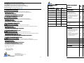
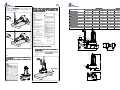
SECTION 3
TECHNICAL FEATURES
c.
d.
2 pole 50 Hz - VORTEX IMPELLER
P2
P1
ThreeThree-phase 400V - 50 Hz
HP
KW
KW
A max
Cable m.
DNM
Solid passage Ø
SEMISOM 1555/80 T
5,5
4
5,34
9,15
10
80
74
SEMISOM 1255/80 T
5,5
4
5,31
9,1
10
80
74
SEMISOM 1055/80 T
5,5
4
5,41
9,2
10
80
74
SEMISOM 1775/80 T
7,5
5,5
6,8
11,9
10
80
74
SEMISOM 1675/80 T
7,5
5,5
7
12
10
80
74
SEMISOM 1375/80 T
7,5
5,5
6,8
11,9
10
80
74
SEMISOM 2100/80 T
10
7,5
9
16,2
10
80
74
SEMISOM 1600/80 T
10
7,5
9
16,2
10
80
74
SEMISOM 1200/80 T
10
7,5
9,1
16,4
10
80
74
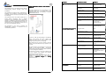
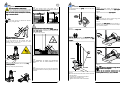
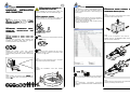
Turn the MAINS SWITCH on “1” for 1 (one)
second,
second then reposition it on “0” zero.
Check the RECOIL of the electric pump. IT
MUST BE OPPOSITE TO THE SENSE OF THE
ARROW
1”
0
4.2.8
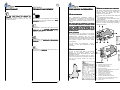
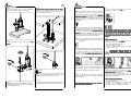
Paying attention to the electric cable, gently let
the electric pump down until it reaches the place
of installation.
4.2.9
Operation to executed by two persons!
Release the safety hook and position the electric
pump close to the system flange.
4.2.10
Position the gasket between the two flanges.
1
4.2.12
Flow rate
m³/h
0
12
24
30
36
48
60
l/m
0
200
400
500
600
800
72
78
90
96
108
114
123
1000 1200 1300 1500 1600 1800 1900 2050
Total manometric head in meters
1555/80 T
1255/80 T
14
13,6
13
12,6 12,1 10,6
8,2
6,3
15,5 14,8 14,1 13,7 13,2 11,9
9,7
7,7
5,5
4
4.2.9
1055/80 T
17
16,5 15,9 15,5 15,1 13,7
11,4
1775/80 T
17
16,5 15,9 15,5 15,1 13,7
11,4
9,1
8,1
6,5
5,7
1675/80 T
19
18,3 17,6 17,2 16,8 15,6
13,7
11,1
9,9
8,1
7,4
1375/80 T
21
20,1
19
18,5
18
16,8
15
12,7
11,6
2100/80 T
21
20,1
19
18,5
18
16,8
15
12,7
11,6
9,6
8.7
1600/80 T
24
23,2 22,3 21,7 21,3 19,9
18,3
16,1
14,9
12,6
1200/80 T
27
25,7 24,4 23,8 23,2
20,4
18
22
4,4
6,7
5,7
4
♦
If the SENSE OF ROTATION is correct,
proceed as follows.
4.2.10
2 pole 50 Hz - DOUBLE CHANNEL IMPELLER
P2
P1
ThreeThree-phase 400V - 50 Hz
HP
KW
SEMISOM 2700/80 T
11
8
KW
Portata
10,4
A max
Cable m.
DNM
Solid passage Ø
18
10
80
45x62
If the SENSE OF ROTATION is not correct, it is
nec essary
FOR THE ELECTRIC
MAINTENANCE OPERATOR to invert two poles
at the terminal board of the MAINS SWITCH.
Afterwards, repeat the operations at
4.2.7 a, b, c, d.
d
4.2.11
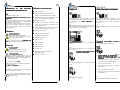
Introduce the bolts into the holes and screw in the
nuts. Tighten all nuts well.
NOTE!
A wrong SENSE OF ROTATION provokes reduction
of flow rate, rise in absorption and damages to the
electric pump.
4.2.12
Let the Power Supply Cable out from the basin; fix
it firmly with clamps, fairleads, etc., so that it will
not get to the basin bottom and close to the
suction of the electric pump .
♦
Flow rate
m³/h
0
30
45
60
72
78
90
l/m
0
500
750
1000
1200
1300
96
1500 1600
108
123
135
150
165
1800
2050
2250
2500
2750
12,1
10,4
8,7
6,5
4
4.2.11
Total manometric head in meters
2700/80 T
20
18,5
17
15,8
15,3
14
13,4
4 pole 50 Hz - VORTEX IMPELLER
P2
P1
ThreeThree-phase 400V - 50 Hz
HP
KW
SEMISOM 1504/80 T
3,5
2,6
KW
Portata
3,64
A max
Cable m.
DNM
Solid passage Ø
8,15
10
80
74
Flow rate
m³/h
0
12
24
30
36
48
l/m
0
200
400
500
600
800
60
66
72
78
84
90
e.
1000 1100 1200 1300 1400 1500
Total manometric head in meters
1504/80 T
9,7
9,3
8,8
8,6
8,3
7,6
6,8
6,3
5,8
f.
5,4
4,9
P1 = Maximum power absorbed by the mains P2 = Nominal power of the motor
4,4
12
Disconnect the electric pump from the
terminal boards of the MAINS SWITCH.
SWITCH
The check OF THE SENSE OF ROTATION is
finished.
4.2.13
THE INSTALLATION OF THE ELECTRIC PUMP
WITHOUT DESCENT AND ANCHORAGE DEVICE is
finished.
17