1
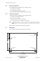
LAN9514 Evaluation Board User Manual 2.5.1 Bus-Powered Operation For bus-powered operation, the EVB9514 must be configured as follows: 2.5.2 JP1 must be in the 1-2 position JP22 must be in the 1-2 position The S1 power switch must be in the open position The +5V power brick must be disconnected from the P1 barrel plug Self-Powered Operation For self-powered operation, the EVB9514 must be configured as follows: JP1 must be in the 2-3 position (5V select) JP22 must be in the 2-3 position The S1 power switch must be in the closed position The +5V power brick must be connected to the P1 barrel plug Note: The EVB9514 includes a 3A fuse (F1) to protect from overcurrent conditions during selfpowered operation. If this fuse becomes damaged, it can be replaced with a 3A Littlefuse154003. Note: Self-powered operation is the default EVB9514 configuration. 2.6 Mechanicals Figure 2.2 details the EVB9514 mechanical dimensions and properties. 0.200 Ø0.125 0.800 2.500 Ø0.125 Ø0.125 Ø0.125 0.200 0.200 0.200 4.000 TOP VIEW Figure 2.2 EVB9514 Mechanicals Revision 1.0 (12-04-12) USER MANUAL 6 SMSC LAN9514