1
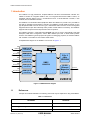
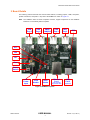
LAN9514 Evaluation Board User Manual
2.3
Test Points
Table 2.3 Test Points
TEST POINT
DESCRIPTION
CONNECTION
TP2
Single pin populated gold post GND testpoint GND
TP3
Single pin unpopulated nRESET
nRESET
TP4
Single pin unpopulated CLK24_EN
CLK24_EN
TP5
Single pin unpopulated CLK24_OUT
CLK24_OUT
TP7
Single pin unpopulated VDD18CORE
VDD18CORE
TP8
Single pin unpopulated VDD18USBPLL
VDD18USBPLL
2.4
System Connections
Table 2.4 System Connections
PLUG/HEADER
DESCRIPTION
PART
J15
10-pin populated GPIO header
10-pin (1x10) header
J16
6-pin populated JTAG header
6-pin (1x6) header
P1
+5V DC power connector
Barrel plug, 2.0mm, center positive
P3
USB type B right angle - upstream
AMP 292304-1
P4
USB type A right angle - downstream
FCI 87520-0010BLF
P5
USB type A right angle - downstream
FCI 87520-0010BLF
P6
USB type A right angle - downstream
FCI 87520-0010BLF
P7
USB type A right angle - downstream
FCI 87520-0010BLF
2.5
Power
Table 2.5 Power Switch
SWITCH
S1
DESCRIPTION
PART
SPDT tiny toggle power switch
Connects +5V brick power to board
The EVB9514 supports both bus-powered and self-powered modes of operation. The following
subsections detail the proper power settings for bus-powered and self-powered operation.
SMSC LAN9514
USER MANUAL
5
Revision 1.0 (12-04-12)