1
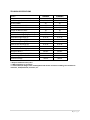
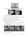
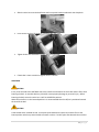
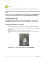
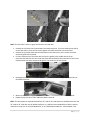
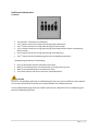
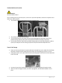
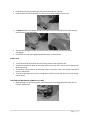
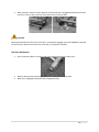
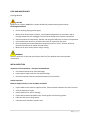
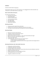
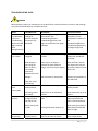
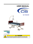
PRIME CARE B900 BED FRAME OWNER’S MANUAL 1 | P a g e STANDARD CONVENTIONS USED IN THIS MANUAL Note: The information within this document is subject to change without notice. This manual includes important information about safety of personnel and equipment. As you read through this manual be aware of the four signal terms. DANGER Information that appears under the DANGER description concerns the protection of personnel from direct and pending hazards that, if not avoided, will result in immediate, serious personal injury or death in addition to damage of the equipment. WARNING Information that appears under the WARNING description concerns the protection of personnel from possible hazards that can result in injury or death in addition to damage of the equipment. CAUTION Information that appears under the CAUTION description concerns the protection of personnel from possible hazards that may result in minor injury or damage of the equipment. NOTE Information that appears under the NOTE description gives added information, which helps in understanding the item being described. 2 | P a g e FEATURES AND TECHNICAL SPECIFICATIONS Standard Features 76” or 84” Sleep Surface Travel Range: Low‐to‐Roll‐7.5”‐30.125” Roll‐at‐any‐Height‐6.875”‐30.875” Locking System: Low‐to‐Roll‐Foot Pad Lock Mechanism Roll‐at‐any‐Height‐Foot Lock Mechanism Pendant Connection on left and right sides Cable connection for Attendant Control Panel Welded Tubular Frame Slat Sleep Deck Wall Guard Heavy Duty Casters Mattress Retainers Heel Lift Ratchet Length Extender Soft Pearl Gray Frame Color Accessories and Options Primus Medical 76”, 80”, and 84” Foam Mattresses Primus Medical Air Force One and Concord Plus Air Mattresses Primus Medical End Panels 42” Width Extension Staff Control Panel Assist Bar Prime Mat Battery Back‐Up Trapeze and Adapter 42” Mattress Expander Overlay Bed Frame Serial Numbers When ordering parts or when contacting Primus Medical Customer Service Department, please include bed’s model and serial numbers, found on the identification labels. The identification labels are located under the sleep deck on the frame rail below the head section on either side of the bed. 3 | P a g e TECHNICAL SPECIFICATIONS Model Length Overall Length (with head & foot boards) Overall Width* Overall Width* with 1 Extension Overall Width* with 2 Extension Length of Mattress Deck Mattress Deck Height (low position) Mattress Deck Height (high position) Head deck angle range (X) Thigh deck angle range (Y) Foot deck angle range (Z) Knee to foot deck angle (K) Trendelenburg Capable** Reverse Trendelenburg Capable** Weight of Bed*** Maximum Weight Capacity**** Input Voltage Actuator Voltage PCB900LR 76"/80"/84" 85¼"/89¼"/93¼" 35" 39" 42" 78" 7½" 30⅛" 0° to 70° 0° to 32° 0° to 11° 0° to 43° Yes Yes 202 Lbs. 500 Lbs. 110V AC 24V DC PCB900RH 76"/80"/84" 85¼"/89¼"/93¼" 35" 39" 42" 78" 6⅞" 30⅞" 0° to 70° 0° to 32° 0° to 11° 0° to 43° Yes Yes 219 Lbs. 500 Lbs. 110V AC 24V DC *Assist Bars add 3” to each side of the bed **Requires footboard control panel ***Without mattress or accessories ****This includes the weight of the resident/patient and all other accessories including, but not limited to mattresses, head/footboards, assist bars, etc. 4 | P a g e SAFETY NOTE: The information contained in this document is subject to change without notice. DO NOT operate this product without first reading and understanding this user manual. Damage or injury may result from improper use of this product. WARNING DO NOT plug anything into housing components of bed (pendants or actuators) while power cord is plugged into the wall outlet. Any cords or tubing used on or with this bed MUST be routed and secured properly to ensure that they do NOT become entangled, kinked or severed during normal operation of the bed. DO NOT use near explosive gases. Possible Fire Hazard if the use of nasal mask in ½ bed tent O₂ administering equipment. If O₂ tent is being used it should not fall below mattress deck. The pendant should not be placed in oxygen enriched environment such as an O₂ tent. Possible Injury or Death may occur if replacement parts are not provided by Primus Medical, LLC on any Primus Medical bed. Possible Injury or Death may occur if accessories are not provided by Primus Medical, LLC for Primus Medical beds. Please contact Primus Medical for accessories that are compatible before use of bed. Possible Injury may occur when activating the Foot Lock Mechanism. This feature was designed to be activated by your foot. Using your hand could result in injury. Caution‐This bed frame complies with EMC requirements of IEC 60601‐1‐1. Radio transmitting equipment, cell phones or similar electronic devices, used in proximity of the bed, may affect the beds performance. The Primus Medical Low‐to‐Roll and Roll‐at‐any‐Height beds are intended for use within an institutional healthcare environment (ie: Skilled Nursing, Transitional Care, Rehabilitation Care, Assisted Living). Primus Medical recommends compliance to the regulations and guidelines specified by your facility. DO NOT roll the bed over any power or pendant cords. Keep all moving parts free of obstructions. 5 | P a g e DO NOT use assist bars as handles for moving the bed. NEVER permit more than one (1) person in/on the bed at any time. The weight capacity of this bed is 500 pounds. Body weight should be evenly distributed over the sleeping surface of the bed. Avoid situations where entire body weight is on a raised head or foot surface. This includes while assisting the user in repositioning or transferring in or out of bed. NEVER allow anyone under the bed at any time. Supervision is required when this product is operated by or near children or people with disabilities. Ensure that the individual using this bed is properly positioned, particularly when the bed is being operated or moved. DO NOT let any body parts protrude over the side or between parts, especially when the bed is being moved or operated. Caster and floor locks (if equipped) shall be used except when bed is being moved. This bed is equipped with a three‐prong grounding plug for protection against possible shock hazard. DO NOT under any circumstances cut or remove the grounding prong. DO NOT open any actuators, control boxes or pendants. Service is only to be performed by authorized service personnel. If unauthorized service is performed on any components the warranty is void. Possible Injury may occur if bed is not kept in lowest position except when care is being provided. Bed should be at lowest suitable height for entry and exit. Possible Injury or Death may occur due to pendant cord being a source for entangling patient/resident. Patients/residents with decreased mental acuity should NOT have access to pendant. Possible Injury or Death may occur if bed is pushed over abrupt thresholds while bed is occupied. This bed was not designed to transport patients. 6 | P a g e ENTRAPMENT WARNING Accurate assessment of the patient and monitoring of correct maintenance and use of equipment are required to prevent entrapment. For additional information on product and safety issues for bed frames and rails refer back to product manuals. If bed frames have been serviced or any other adjustments have been made, make sure all parts are securely back in place before operating the bed frame. Other manufacturers assist bars may not be compatible and can lead to entrapment issues or harm to patients. Make sure mattress is the correct size for bed frame and the assist bars are secure to frame to decrease the risk of entrapment. PRIMUS MEDICAL COMPLIANCE INFORMATION Matching the correct bed components to meet regulatory specifications can be complicated. Primus Medical offers a wide variety of compliance options. Primus Medical can assist your facility in selecting correct components or accessories that is recommended for the specific bed model. MATTRESS SPECIFICATIONS WARINING Possible ENTRAPMENT Hazard may occur if you do not use the recommended specification mattress. Resident entrapment may occur leading to injury or death. A mattress may not be included with this bed. It is recommended that a 35” wide mattress that is made to fit the length of a 76”, 80”, or 84” bed frame is used, such as a Primus Medical Redistribution Mattress. This mattress must be a minimum of 5 ½ inches and maximum of 8 inches. Also available is the EXP42 Mattress Overlay which converts any 35”x80” foam mattress to a 42”x80” Redistribution Mattress when the width extension is in place. UNPACKING INSTRUCTIONS (tools needed: Pliers or Wire‐cutters) CAUTION DAMAGE to the equipment may occur if the zip ties are removed wrong. If the package is standing, slowly lower to the floor. It may be necessary for two or more people to help in lowering the bed. Cut black strapping around box; remove box ends and plastic surrounding bed frame. 7 | P a g e Cut zip ties to remove wall guard at the head of the bed. Cut the zip ties to remove mattress retainers on each side of the bed. Remove ties from pendant. Remove any remaining zip ties or foam left on bed frame. Locate power cord and plug into grounded 110‐120V outlet. Raise the bed frame and check to make sure everything is plugged into the control box and no wires are loose. If wires are not in control box, match up by the color coded system. (See instructions below) NOTE: DO NOT remove zip ties that are holding any cords underneath bed frame. ASSEMBLY Tools Needed: ¾” Wrench and Socket Utility Knife 3/16” Hex Key ½” Wrench MATTRESS RETAINER ADJUSTMENT Mattress Retainer is designed to keep the mattress in place on the sleep surface. Determine what the length of bed you will need to use. Please read important information on Mattress Retainer and follow instructions on installation. Use the 76”, 80” and 84” guide on the head and foot section to place your mattress retainer in the correct spot. If you are using a 76” bed frame there is no need to move the mattress retainers at the head and foot section. If you are using a 80” bed frame you will need to move the head and foot section mattresses retainers to the 80” slots which is the middle position. If you are using an 84” bed frame you will need to move the head and foot section mattress retainers to the 84” slots which are the last slots closest to the head and foot boards. 8 | P a g e The remaining mattress retainers on the perimeter of the sleep deck should be moved in the upward position. Place mattress on mattress support deck. The mattress should now be snug against all of the mattress retainers. Replace mattress, making sure mattress fills length between Mattress Retainer stops. Also, make sure the mattress does not compress below 1.5” under patient/resident weight. HEADBOARD AND FOOTBOARD INSTALLATION AND ADJUSTMENT NOTE: 3/16” Hex key required for initial mounting of headboard and footboard support assemblies. This tool is also required for bed length adjustment. Insert headboard or footboard support assembly, whichever is appropriate for the end of the bed you are working on. There are mounting positions for 3 different mattress lengths, 76”, 80” and 84”. Choose the one appropriate for your mattress. NOTE: This location can be changed at any time by removing the 3/16” bolts and sliding the support assembly to the desired position. 9 | P a g e Thread the 3/16” bolt into both sides of the bed frame to hold the headboard/footboard support assemblies in place. Open the cam locks on the support assembly. Place the tubes of the headboard/footboard mounting brackets into the slots of the support assembly. NOTE: The mounting brackets on the footboard face toward the inside of the bed and those of the headboard face away from the bed. Slide headboard/footboard down until it stops. Close the cam locks to lock the headboard/footboard in position. ADDITIONAL INSTRUCTIONS FOR CONTROL PANEL EQUIPPED FOOTBOARD Route the cable from the control panel toward the control box keeping clear of any areas that could pinch or abrade the cable. Secure the cable to the frame in several locations along its length. ASSIST BAR ASSEMBLY (Tool Less Assembly) To install assist bar(s) locate the bracket under the sleep deck. 10 | P a g e Slide the assist bar onto the bed frame and line up with bracket underneath the sleep deck. Insert screws and use (2) Knobs to hold Assist Bar into place. Tighten knobs until Assist Bar is secure against the bracket. If Assist Bar is loose continue to tighten until it is secure. ASSIST BAR CAUTION It may cause the bed to be UNSTABLE due to the interference between the assist bar and the floor when lowering the bed. An unstable bed may tilt and/or cause property damage or personal injury. Before lowering the bed, ensure the assist bar is NOT in HORIZOTAL position. When the assist bar is in the lowered position it is recommended that the rail/bar is positioned toward the head of the bed. CAUTION Crush Hazard when installed on bed. Pinch point exists between the assist bar and the floor at the lowest position which may cause INJURY to oneself or others. Do NOT place feet beneath the assist bar. 11 | P a g e WARNING Patient entrapment with assist bars may cause injury or death. To prevent patient entrapment the mattress must fit bed frame and side rails snugly. Please follow the manufacturer’s instructions and monitor patient frequently. Please read and understand the owner’s/operator’s manual prior to using this bed. Crush point exists due to LOW BED CLEARANCE. Lowering the bed may cause oneself or other INJURY. Stay clear of the frame and ensure children or pets are not under the bed before lowering the bed. ENTRAPMENT WITH ASSIST BAR If assist bar is positioned incorrectly this may result in PATIENT ENTRAPMENT. To prevent PATIENT ENTRAPMENT the bar needs to be placed in the correct area, as shown in the instructions below. WIDTH EXTENSION ASSEMBLY (Tool Less Assembly) Determine if you will be making the bed frame a 39” or 42” bed frame. Use only (1) Width Extension if a 39” bed frame is going to be used. Use both Width Extensions if a 42” bed frame is going to be used. Remove the deck width extension assemblies from their packaging. DO NOT remove the strings attached to the Width Extension they are to keep from losing the clamps. There are three (3) sections to each side of the Width Extension. Piece together and insert the three (3) 3/16” x 1 ¼ “ bolts into the hinge points as shown. FULLY TIGHTEN! 12 | P a g e NOTE: This will make it easier to grasp and attach to the bed deck. Remove the (4) knobs that are attached to the width extension, (2) on the head section and (2) on the foot section, these will be used to tighten the width extension to the bed frame. Remove the (2) knobs underneath the bed frame at the mid‐section, this is where the width extension guides will be placed. Line the extension up to the sleep deck and use the guides at the middle section of the extension and slide into the slots under the sleep deck attached to the mid section of the frame. Replace knobs that were removed and tighten until secure to the mid‐section. Now begin at either head or foot section and replace the plastic forming clamps and knobs to the Width Extension. Make sure all knobs are tightened or the width extension will not be secure to sleep deck. Repeat process for other side if additional width is desired. NOTE: This bed expansion expands the bed from 35” wide to 39” wide with one (1) Width Extension and 35” wide to 42” wide with two (2) Width Extensions. It is HIGHLY recommended that a 500 lb. capacity mattress be used, such as a Primus Medical 39” or 42” Redistribution Mattress. Also available is the 13 | P a g e EXP42 Mattress Overlay which converts any 35”x80” foam mattress to a 42”x80” Redistribution Mattress. HEEL LIFT RATCHET With the knee‐foot section set at the preferred position, lift the foot panel. There are six fixed stops on the heel lift that it can be set at. The panel must be lifted slowly to connect each stop. The heel lift cannot be lowered to a lower adjustment without resting in the lowest position. To lower the panel, lift the panel to the last setting and lower it in one motion. In the lowest position the panel can then be lifted to the lowest position. 14 | P a g e BATTERY BACK‐UP (Tools Needed: Phillips Screw Driver and 9mm Wrench and Socket) Locate the mounting plate underneath the bed frame near the head of the bed. Attach the mounting bracket to the mounting plate by screwing (2) bolts at the top into the frame. Secure the rest of the mounting bracket with the remaining (4) bolts and locknuts to the mounting plate. Slide the battery into place; make sure it is secure into the mounting bracket. Attach the cord from the battery into the control box (black color). The battery back‐up will now work if the bed becomes unplugged from the wall outlet or there is a power failure. BED FUNCTIONS Hand Control Operation CAUTION CRUSH Hazard Do Not place feet under the frame when lowering the bed. 4 Function Hand Pendant This pendant can be plugged into the left or right side of the bed for the convenience of the patient. The top buttons control the raising and lowering of the head section. The 2nd set of buttons control the raising and lowering of the foot section. The 3rd set of buttons control the raising and lowering of the head and foot section simultaneously (Auto Contour). The last set of buttons control the raising and lowering of the bed frame. When the green light on the pendant is lit this indicates the pendant is in use. 15 | P a g e Staff Control Pad Operation 5 Function This controller is located on the footboard The 1st button controls the raising and lowering of the head section. The 2nd button controls the raising and lowering of the foot section. The 3rd button controls the raising and lowering of the head and foot section simultaneously (Auto Contour). The 4th button controls the raising and lowering of the bed frame. The 5th button controls trendelenburg and reverse trendelenburg positions. Trendelenburg and Reverse Trendelenburg Hi/Lo Lockout option with the Attendant Control Pad While in the locked position, the Hi/Lo feature on the panel will not work. While in the unlocked position, all features will work. The contour position will work in the lock or unlocked position. CAUTION The use of Trendelenburg and Reverse Trendelenburg function may not be suitable for certain patients. This function should only be used with the recommendation from medical personnel. A Primus Medical Bed Length Extension should not be used on a bed that has the Trendelenburg and Reverse Trendelenburg function. 16 | P a g e Pendant Holder and Location DANGER Electrical SHOCK Hazard Prior to working with any electrical parts, such as the 13‐pin hand pendant, make sure the power to the bed frame is disconnected. The pendant holder is to be placed at the top of the assist rail. The pendant then slides into the holder. To move the pendant to the other side of the bed, disengage the main power then lift the pendant locking hood up and remove the pendant end from the housing component. On the other side of the bed, lift the pendant locking hood on the housing component and line up the pins and push into the housing component and push hood around pendant end. Power Cord Storage Power cord strain relief hook is located underneath the bed frame at the head of the bed keeps the power cord off the floor and protects the power cord from getting severed or ran over. If the power cord is not in place under the bed, untie the power cord and stretch out toward the head of the bed. Unscrew the cap that is attached to the power cord and run cord down through the hook. After the cord is through the hook, screw the cap together, this will hold the power cord in place. 17 | P a g e Note: Make sure to disconnect the main power cord from the wall outlet and store the power cord when the bed is not in use. Make sure the power cord is placed on the sleep deck and not hanging off the bed where it may be damaged. Bed Mobilization and Stabilization WARNING Involuntary bed movement may take place if the floor lock or bed casters are left unlocked. Involuntary bed movement may lead to property DAMAGE or resident INJURY. Never leave a bed unattended while the floor lock is disengaged. Floor Lock Operation Press the floor lock bar down with your foot. Two black plungers extend to the floor on each side the bed in between the wheels indicating that floor lock is engaged. 18 | P a g e By the floor lock being occupied this will prevent the bed from moving. Press the floor lock bar down with your foot and this will disengage the floor lock. A YELLOW indicator will appear on top of the caster covers on each side of the bed indicating the floor lock is now disengaged. The two black plungers will also now be off of the floor indicating that the floor lock is disengaged. By the floor lock being disengaged the bed will move in all directions. Caster Lock To lock the head of the bed use the two locking casters at the top of the bed. To lock the casters push down on the caster knobs on the top of the caster, this will prevent the bed from moving. To unlock the casters push up on the caster knobs on top of the caster, this will allow the bed to move in all directions. The Low‐to‐Roll bed frame has four locking casters and these work the same as the two locking casters above. Foot Pad Lock Mechanism (PCB900 Low‐to‐Roll) When the bed is at its lowest position the Foot Pad Lock is disengaged and the bed is able to move in all directions. 19 | P a g e When the bed is above its lowest position the Foot Pad Lock is engaged and the bed cannot be moved, it is secure due to the four foot pads on each end of the bed. CAUTION Moving the bed while the floor lock, caster lock, or foot pad is engaged may cause DAMAGE to the bed. Do not move the bed until the floor lock, caster lock, or foot pad is unlocked. Bed Steer Mechanism Steer mechanism (Bale) is on either side of the head end resting on caster cover. With the locking caster tab facing out, flip the steer mechanism (Bale) back. When this is engaged, the bed will steer straightforwardly. 20 | P a g e CARE AND MAINTENANCE Cleaning Method CAUTION Equipment or property DAMAGE or resident INJURY may take place during maintenance. Cleaning Instructions Prior to cleaning unplug power supply. Make sure all electrical parts (motors, control boxes and pendant) are not broken and all housing components are unplugged. Ensure that NO liquids enter electrical components. Sanitize and wash all components. DO NOT sub merge the bed frame or electrical components. Use standard water pressure. DO NOT power wash or steam clean any parts. Rinse completely with water (Maximum temperature 110°F or 43°C). solvents, alcohol or petroleum should not be used on the bed surface. Make sure all parts are dry before using or storing. WARNING Failure to take care of your bed may decrease the life of your product and increase product maintenance. INITIAL INSPECTION Inspection of All Components – Receipt of assembled bed Check bed components for obvious damage. Inspect power supply cords for cuts and/or damage. Check that actuator cords are connected properly to the controller. Annual Inspection Mattress Support Surface, Frame and Base Assemblies Inspect welds on the mattress support surface, frame and base assemblies for stress fractures. Verify all fasteners are tight. Inspect fasteners for wear or damage. Inspect bed and Assist Bars/Rails bolts, if loose tighten and if missing replace. Lubricate clevis pins at hinge points. Lubricate tracks of bed for smooth travel. 21 | P a g e Actuators Inspect push tubes and end connections of all actuators for excess wear or bending. Verify that all clevis pins are in place. Casters Check that locks on casters lock properly (if equipped). Check that all casters roll properly. Check bed brake mechanism for proper function (roll at any height model). Check caster alignment mechanism to verify proper function (roll at any height model). Semi‐Annual Inspection Control Box Check power cord for chafing, cuts or wear. Make sure all attachment hardware and brackets are tight. Check electrical connections for wear or fractures. Verify that all actuator connections are tight. Pendant Check pendant cord for chafing, cuts or wear. Check all pendant buttons for proper function. Actuators Check actuator cords for chafing, cuts or wear. Check to make sure actuators do not bind at any point throughout their full range of motion. Authorized Accessories Inspect all fasteners for looseness and wear. Replace or tighten as necessary. Ensure proper function of accessory. Ensure welds do not have stress fractures. Ensure no tubes are bent. Quarterly Maintenance Check If the bed has a battery, unplug from the wall outlet and validate function. The battery may be built‐in or portable. Inspect bed and Assist Bars/Rails bolts, if loose tighten and if missing replace. Lubricate clevis pins at hinge points. Lubricate tracks of bed for smooth travel. 22 | P a g e SERVICING Actuators and Control Box are light gray. Possible Shock Hazard may occur if the Control Box is not unplugged from the wall outlet before any maintenance is performed on Motor or Control Box. Motor and Control Box Information Cord and Socket Identification Attendant Control (Green) Hand Pendant (Red) Head Section Motor (Black) Foot Section Motor (Yellow) Hi/Lo Motor (Blue) Hi/Lo Motor (White) Battery Back‐Up (Black) Removing Control Box Unplug main power supply from the wall outlet. Remove the (2) screws that are holding the control box to the actuator. The outlets on the control box are color coded so they can be reinstalled later. Removing the Motor Identify the motor that needs replaced. Tip bed on its side to remove the Hi/Lo motors. Unplug motor cord from control box. Motor is held in place by (2) cotter pins. Those can be removed with your fingers. Slide pins out of holes, they should come right out. You can now replace motor. To reassemble bed, reverse previous steps, and make sure to: ‐Assemble cotter pins as originally installed, ‐Zip ties should be replaced, with cords to their original position and routing direction to the control box. Removing the AC Power Cord (tools needed‐T10 Star Key) Unplug power cord from wall outlet. Locate power cord end on control box. Unscrew (4) bolts from the control box. Lift power cord from control box and remove (2) wires from the terminal inside the control box. Dispose of the broken power cord. Reattach (2) new wires to terminal inside control box. Screw (4) bolts back on to the control box. Plug power cord back into wall outlet. 23 | P a g e TROUBLESHOOTING GUIDE WARNING Before doing any repairs or maintenance to the bed frame, read all instructions, cautions, and warnings. The repairs should be done by a skilled technician. Effect Possible Cause Verification Corrective Action The bed must be leveled When raising/lowering the bed Actuators start When in the frame while in the reading for Trendelenburg out before you can possible overload Trendelenburg/Reverse or Reverse raise/lower it. Make sure Trendelenburg position, bed and stop so the Trendelenburg the begins to raise/lower then stops position the bed bed does Trendelenburg/Reverse and beeps begins to beep Trendelenburg position is when no longer being used. raising/lowering. Floor lock is not engaged. Black plunger is not hitting the floor or there is not enough resistance between floor and plunger. Floor lock is not functioning. Bed is not in its Bed does not lowest position. move (Low‐to‐Roll) All locking casters are locked. Bed not steering Bed is only moving correctly straight forward not side to side. Bed is moving side to side. Actuators are Wire connections not working may be loose or Bed does not stay in place Yellow indicator on caster housing is visible. There may be an object in‐ between the floor and black plunger, the floor may be slippery. Floor lock stuck in one position. Activate floor lock Yellow lock should NOT be visible. Clean the floor; remove any objects that may be in the way. Make sure the floor is dry. Contact Primus Medical 1‐ 877‐638‐2776. Casters are not touching the floor. Caster locks are in downward position. Steering mechanism (Bale) is down. Steering mechanism (Bale) is up. Use pendant to put in its lowest position. Push caster locks up on all casters. Push steering mechanism (Bale) up and bed will move in desired position. Push steering mechanism (Bale) down and bed will move straight. Reconnect any loose wires and/or power Visually check wire connections. They may be loose or frayed. 24 | P a g e damaged. Hi/Lo lockout may be on. Faulty actuator. Faulty pendant. Bed stalls while operating Thermal shut down. Bed is out of synchronization The motor becomes unplugged. The bed becomes caught on chair rail. The light on the attendant control panel is on. Disconnect power cord from bed that is not functioning and use on another bed that is functioning. Reconnect the power and test functions on that bed. A faulty actuator will not work with any connection port. Check pendant cord connection, power supply, Hi/Lo lockout is off and pendant is not functioning. Disconnect pendant cord connection with a functioning pendant if available. Connect and test functions. Bed works for a short period of time the cuts out. Check for obstructions or any interference with bed frame, such as window seal or too much weight on bed frame. The motor becomes unplugged and it gets plugged back in and the synchronization is off. The bed gets caught on the chair rail and it causes the bed to go into tilt position. cords. If cord is frayed replace immediately. Unlock panel by pushing lock button and light should go off. Contact Primus Medical 1‐ 877‐638‐2776. Contact Primus Medical 1‐ 877‐638‐2776. Wait a period of time before using the bed frame again. DO NOT keep trying to override this will shorten the life of your product. Remove at least one end on both of the Hi/Lo Actuators on the bed. Retract the actuators all the way by pressing the bed up and down buttons at the same time. Once both actuators have retracted fully‐this can happen at different speeds‐the green LED at the top of the handset will light, the controller will click and emit an audible beep. System is now synchronized. 25 | P a g e OPTION 80” and 84” BED EXTENSION (tools needed: 3/16” Hex key) Both ends of the bed need to be used for the extension to be complete. There are three different mattress lengths, 76”, 80”, and 84”. Choose the appropriate length for your mattress. NOTE: This location can be changed at any time by removing the 3/16” bolts and sliding the support assembly to the desired position. Thread the 3/16” bolt into both sides of the bed frame to hold the desired length. When the assembly bar is pulled out to the first slots it is at the 76” length. When the assembly bar is pulled out to the first slot at the head of the bed and second slot at the foot of the bed it is at the 80” length. When the assembly bar is pulled out to the second slots it is at the 84” length. Possible injury or death may occur if the use of a mattress is not long enough so the gap between the mattress and head and foot board is small enough to prevent the patient/resident from getting their head/neck caught in the gaps. Make sure increase in total length of bed frame does not present a safety hazard or impair access in room. Place new mattress against Mattress Retainer and be sure mattress covers entire length of mattress support surface. 26 | P a g e Primus Medical, LLC Warranty Primus Medical’s Prime Care 900 Beds, Models PCB900LR and PCB900RH, are guaranteed for a 3 year period from the date of delivery. This guarantee is against defects in materials and craftsmanship, under normal use and service. This 3‐year warranty includes electrical and mechanical parts and components. Welds are covered under lifetime¹ warranty of the product. Steel structural components are covered under the 15‐year warranty from the date of delivery. Damage caused by use in inappropriate environmental conditions, mistreatment or failure to maintain the product in agreement with user and service instructions is not covered under warranty. Any change, adjustments, or repair unless performed or authorized in writing by Primus Medical, will void the warranty. Parts Primus Medical beds contain a variety of parts that wear from normal use. Some products are not covered under the 3‐year warranty but do fall under the 90‐day warranty, such as DC batteries. Primus Medical’s responsibility under this warranty is limited to supplying replacement parts, servicing or replacing, at its option, which is found to be faulty by Primus Medical. Warranty replacement parts are covered by the warranty until the product’s 3‐year warranty period expires. For warranty replacement, Primus Medical requests that broken parts be sent back to them for evaluation. A credit will be issued only after the inspection. Service A majority of service requests can be handled by the facility maintenance department with assistance from the Primus Medical tech support. If a Primus Medical technician is required one will be provided by Primus Medical at our discretion. Most parts can be shipped next day air at the customer’s expense. This warranty is extended to the original purchaser of the equipment. ¹ Weld lifetime defined as 20 years 27 | P a g e APPENDIX SPECIAL NOTE For your convenience, we have provided the January 2008 addition of the FDA’s guide to bed safety. This information from the FDA’s brochure, published by Hospital Bed Safety Workgroup, is replicated verbatim; the latest version is available at http://www.fda.gov. A Guide to Bed Safety Bed Rails: In Hospitals, Nursing Homes and Home Health Care: The Facts Bed Rail Entrapment Statistics Today there are about 2.5 million hospital and nursing home beds in use in the United States. Between 1985 and 2008, 772 incidents of patients* caught, trapped, entangled, or strangled in beds with rails were reported to the U.S. Food and Drug Administration. Of these reports, 460 people died, 136 had a nonfatal injury, and 176 were not injured because staff intervened. Most patients were frail, elderly or confused. *NOTE: In this brochure, the term patient refers to a resident of a nursing home, any individual receiving services in a home care setting, or patients in hospitals. Patient Safety Patients who have problems with memory, sleeping, incontinence, pain, uncontrolled body movement, or who get out of bed and walk unsafely without assistance, must be carefully assessed for the best ways to keep them from harm, such as falling. Assessment by the patient’s health care team will help to determine how best to keep the patient safe. Historically, physical restraints (such as vests, ankle or wrist restraints) were used to try to keep patients safe in health care facilities. In recent years, the health care community has recognized that physically restraining patients can be dangerous. Although not indicated for this use, bed rails are sometimes used as restraints. Regulatory agencies, health care organizations, product manufactures and advocacy groups encourage hospitals, nursing homes and home care providers to assess patients’ needs and to provide safe care without restraints. The Benefits and Risks of Bed Rails Potential benefits of bed rails include: Aiding in turning and repositioning within the bed. Providing a hand‐hold for getting into or out of bed. Providing a feeling of comfort and security. Reducing the risk of patients falling out of bed when being transported. Providing easy access to bed controls and personal care items. Potential risks of bed rails may include: Strangling, suffocating, bodily injury or death when patients or part of their body are caught between rails or between the bed rails and mattress. More serious injuries from falls when patients climb over rails. Skin bruising, cuts, and scrapes. 28 | P a g e Inducing agitated behavior when bed rails are used as a restraint. Feeling isolated or unnecessarily restricted. Preventing patients, who are able to get out of bed, from performing routine activities such as going to the bathroom or retrieving something from a closet. Meeting Patient’s Needs for Safety Most patients can be in bed safely without bed rails. Consider the following: Use beds that can be raised and lowered close to the floor to accommodate both patient and health care worker needs. Keep the bed in the lowest position with wheels locked. When the patient is at risk of falling out of bed, place mats next to the bed, as long as this does not create a greater risk of accident. Use transfer or mobility aids. Monitor patients frequently. Anticipate the reasons patients get out of bed such as hunger, thirst, going to be the bathroom, restlessness and pain; meet these needs by offering food and fluids, scheduling ample toileting, and providing calming interventions and pain relief. When bed rails are used, perform an on‐going assessment of the patient’s physical and mental status; closely monitor high‐risk patients. Consider the following: Lower one or more sections of the bed rail, such as the foot rail. Use a proper size mattress or mattress with raised foam edges to prevent patients from being trapped between the mattress and rail. Reduce the gaps between the mattress and side rails. Which Ways of Reducing Risk are Best? A process that requires ongoing patient evaluation and monitoring will result in optimizing bed safety. Many patients go through a period of adjustment to become comfortable with new options. Patients and their families should talk to their health care planning team to find out which options are best for them. Patient or Family Concerns About Bed Rail Use If patients or family ask about using bed rails, health care providers should: Encourage patients or family to talk to their health care planning team to determine whether or not bed rails are indicated. Reassure patients and their families that in many cases the patient can sleep safely without bed rails. Reassess the need for using bed rails on a frequent regular basis. To report an adverse event or medical device problem, please call FDA’s MedWatch Reporting Program at 1‐800‐FDA‐1088. For additional copies of this brochure, see the FDA’s website at http://www.fda.gov/cdrh/beds/. 29 | P a g e For more information about this brochure, contact Beryl Goldman at 610‐335‐1280 or by e‐mail at [email protected]. She has volunteered to answer questions. For information regarding a specific hospital bed, contact the bed manufacturer directly. Developed by the Hospital Bed Safety Workgroup AARP ABA Tort and Insurance Practice Section American Association of Homes and Services for the Aging American Health Care Association American Medical Directors Association American Nurses Association American Society for Healthcare Engineering of the American Hospital Association American Society for Healthcare Risk Management Basic American Metal Products Beverly Enterprises, Inc. Care Providers of Minnesota Carroll Healthcare DePaul College of Law ECRI Evangelical Lutheran Good Samaritan Society Hill‐Rom Co., Inc. Joerns Healthcare, Inc. Joint Commission on Accreditation of Healthcare Organizations Medical Devices Bureau, Health Canada National Association for Home Care National Citizens’ Coalition for Nursing Home Reform National Patient Safety Foundation RN+ Systems Stryker Medical The Jewish Home and Hospital Untie the Elderly, The Kendal Corporation U.S. Food and Drug Administration Updated January 2008 30 | P a g e