1
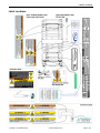
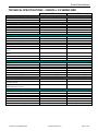
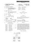
USER MANUAL by Invacare An Invacare Company Read and understand this manual prior to using the bed. This manual contains important information regarding the safe operation of the Carroll CS Series bed. Table of Contents Carroll CS Bed Manual - Table of Contents REGISTER YOUR P RODUCT ...........................................................................................................................................................2 Label Locations.......................................................................................................................................................................5 STANDARD C ONVENTIONS USED IN THIS MANUAL ........................................................................................................................6 Symbols Used on the CS Bed .................................................................................................................................................6 TECHNICAL S PECIFICATIONS - CARROLL CS SERIES BED ............................................................................................................7 MATTRESS S PECIFICATIONS ....................................................................................................................................................... 12 UNPACKING INSTRUCTIONS ........................................................................................................................................................13 ASSEMBLY INSTRUCTIONS..........................................................................................................................................................15 Attach Head and Foot Ends ..................................................................................................................................................15 Install Head and Foot Ends ................................................................................................................................................... 15 Install the Mattress Keeper Rod to the Head and Foot Decks...............................................................................................16 Assist Rail / Assist Bar– Installation.....................................................................................................................................18 Change Assist Rail from “Guard” to “Assist” to “Transfer” ................................................................................................20 Change Assist Bar from “Storage” to “Assist” ..................................................................................................................... 20 UNDERSTANDING B ED FUNCTIONS .............................................................................................................................................21 Hand Control Pendant Operation ..........................................................................................................................................21 Raise Heel Lift Ratchet ......................................................................................................................................................... 22 Lower Heel Lift Ratchet ....................................................................................................................................................... 22 Pendant Stowage and Location.............................................................................................................................................22 Power Cord Stowage.............................................................................................................................................................23 CS Bed Mobilization and Stabilization.................................................................................................................................24 Floor Lock Operation............................................................................................................................................................24 Bed Steer Mechanism ...........................................................................................................................................................24 Cardiopulmonary Resuscitation (CPR) Release (Optional)..................................................................................................25 Using the CPR Release ......................................................................................................................................................... 25 Pendant HILO Lock Out - Optional......................................................................................................................................26 CARE AND MAINTENANCE ..........................................................................................................................................................27 Sanitizing Method.................................................................................................................................................................27 Annual Maintenance Check..................................................................................................................................................27 Quarterly Maintenance Check ..............................................................................................................................................27 Environmental Conditions for Storage and Transport ..........................................................................................................28 Environmental Conditions for Operation..............................................................................................................................28 TROUBLESHOOTING G UIDE......................................................................................................................................................... 29 OPTIONS INFORMATION ..............................................................................................................................................................30 Touch-up Paint......................................................................................................................................................................30 Trapeze Adapter Installation.................................................................................................................................................30 LIMITED WARRANTY OF CARROLL HEALTHCARE , INC. ...............................................................................................................32 APPENDIX................................................................................................................................................................................... 33 A Guide to Bed Safety Bed Rails in Hospitals, Nursing Homes and Home Health Care: The Facts ...................................33 Bed Rail Entrapment Statistics .............................................................................................................................................33 Patient Safety ........................................................................................................................................................................33 The Benefits and Risks of Bed Rails.....................................................................................................................................33 Potential risks of bed rails may include: ...............................................................................................................................33 Meeting Patients' Needs for Safety.......................................................................................................................................34 Which Ways of Reducing Risks are Best?............................................................................................................................34 Patient or Family Concerns About Bed Rail Use..................................................................................................................34 Developed by the Hospital Bed Safety Workgroup..............................................................................................................35 1-150-068-A CS Bed Manual.doc © Carroll Healthcare Inc. Page 1 of 35 REGISTER YOUR PRODUCT The benefits of registering: 1. Safeguard your investment. 2. Ensure long term maintenance and servicing of your purchase. 3. Receive updates with product information, maintenance tips, and industry news. 4. Invacare can contact you or your provider, if servicing is needed on your product. 5. It will enable Invacare to improve product designs based on your input and needs. Register ONLINE at www.invacare.com - or Complete and mail the form on the next page Any registration information you submit will be used by Invacare Corporation only, and protected as required by applicable laws and regulations. 1-150-068-A CS Bed Manual.doc © Carroll Healthcare Inc. Page 2 of 35 PRODUCT REGISTRATION FORM Register ONLINE at www.invacare.com - or Complete and mail this form Name _______________________________________________________________ Address _____________________________________________________________ City ___________________ State/Province __________ Zip/Postal Code ________ Email ___________________________________ Phone No. _________________ Fold here Invacare Model No. ______________________ Serial No. __________________ Purchased From _________________________ Date of Purchase: ___________ Cut Along Line 1. Method of purchase: (check all that apply) ❏ Medicare ❏ Insurance ❏ Medicaid ❏ Other __________________________ 2. This product was purchased for use by: (check one) ❏ Self ❏ Parent ❏ Spouse ❏ Other 3. Product was purchased for use at: ❏ Home ❏ Facility ❏ Other 4. I purchased an Invacare product because: ❏ Price ❏ Features (list features) _________________________________________ 5. Who referred you to Invacare products? (check all that apply) ❏ Doctor ❏ Therapist ❏ Friend ❏ Relative ❏ Dealer/Provider ❏ Other_________ ❏ Advertisement (circle one): TV, Radio, Magazine, Newspaper ❏ No Referral_____ 6. What additional features, if any, would you like to see on this product? __________________________________________________________________________ Fold 7. Would you like information sent to you about Invacare products that may be available for a here particular medical condition? ❏ Yes ❏ No If yes, please list any condition(s) here and we will send you information by email and/or mail about any available Invacare products that may help treat, care for or manage such condition(s): __________________________________________________________________________ 8. Would you like to receive updated information via email or regular mail about the Invacare home medical products sold by Invacare's dealers? ❏ Yes ❏ No 9. What would you like to see on the Invacare website? __________________________________________________________________________ 10. Would you like to be part of future online surveys for Invacare products? ❏ Yes ❏ No 11. User's Year of birth: ______________________________________________________ If at any time you wish not to receive future mailings from us, please contact us at Invacare Corporation, CRM Department, 39400 Taylor Parkway, Elyria, OH 44035, or fax to 877-619-7996 and we will remove you from our mailing list. To find more information about our products, visit www.invacare.com. Part No 1134871 5 Long Term Care Beds Cut Along Line Fold here Fold here Invacare Product Registration Form Please Seal with Tape Before Mailing Long Term Care Beds 6 Part No 1134871 Label Locations Label Locations 1-150-068-A CS Bed Manual.doc © Carroll Healthcare Inc. Page 5 of 35 Product Specifications STANDARD CONVENTIONS USED IN THIS MANUAL Please Note: The information contained in this document is subject to change without notice. This manual includes information essential to the safety of personnel and equipment. As you read through this manual be alert to the four signal words. Information appearing under the DANGER caption concerns the protection of personnel from the immediate and imminent hazards that, if not avoided, will result in immediate, serious personal injury or loss of life in addition to equipment damage. Information appearing under the WARNING caption concerns the protection of personnel from potential hazards that can result in personal injury or loss of life in addition to equipment damage. Information appearing under the CAUTION caption concerns the protection of personnel from potential hazards that can result in minor personal injury or equipment damage. NOTE Information appearing in a NOTE caption provides additional information, which is helpful in understanding the item being explained. Symbols Used on the CS Bed 1-150-068-A CS Bed Manual.doc © Carroll Healthcare Inc. Page 6 of 35 Product Specifications TECHNICAL SPECIFICATIONS - CARROLL CS SERIES BED CS7 CS9 Certifications Canada USA CSA C22.2 No. 601.1 UL Std. 60601-2-38 CSA C22.2 No. 601.1 UL Std. 60601-2-38 7" to 30" (178 to 762 mm) 7" to 30" (178 to 762 mm) 0° to 70° 0° to 30° 14” (356 mm) 9" to 30" (229 to 762 mm) 9" to 30" (229 to 762 mm) 0° to 70° 0° to 30° 14” (356 mm) 120V~ 3.5A max 60 Hz 24 Volts DC (70W max) 10% Max (2 min ON 18 min OFF) 24 Volts DC 24 Volts DC 120V~ 3.5A max 60 Hz 24 Volts DC (70W max) 10% Max (2 min ON 18 min OFF) 24 Volts DC 24 Volts DC 24 Volts DC 24 Volts DC 24 Volts DC standard 24 Volts DC standard Class I Type B IPX4 standard optional optional (24V DC 9.2 Amps) optional (24V DC 9.2 Amps) Class I Type B IPX4 standard optional optional (24V DC 9.2 Amps) optional (24V DC 9.2 Amps) standard optional standard optional optional optional 86-1/4” (2191 mm) 83-3/4" (2127 mm) 80" (2032 mm) 40" (1016 mm) 35-1/2" (902 mm) 190 lb. (86 kg) 500 lb. (228 kg) 86-1/4” (2191 mm) 83-3/4" (2127 mm) 80" (2032 mm) 40" (1016 mm) 35-1/2" (902 mm) 190 lb. (86 kg) 500 lb. (228 kg) Elevation Range (floor to deck) Stability Range (off casters) Mobility Range (on Casters) Head Deck Angle Knee - Foot Angle Under-bed clearance for 2/3 of bed - centered Electrical Specifications Control Box Mains Voltage Control Box Input Current Control Box Current Frequency Control Box Output Voltage Control Box Duty Cycle Motorised Linear Head Actuator Motorised Linear HILO Actuator (head end mount) Motorised Linear HILO Actuator (foot end mount) Motorised Linear Foot Actuator Eight button hand pendant with contour function Safety Features Protective Earth Ground Electric shock protection Enclosure protection Floor Lock Quick Release CPR Handle Built-in Battery Back-up Portable Battery Back-up Security - Pendant Lock-Out Pendant Disconnection ACL (Attendant Control Lockout) Pendant HILO Function Lock-Out ACP (Attendant Control Panel) Individual Pendant Function Lock-Out Dimensions and Weight Length (overall) Length - Between head & foot end Length - Mattress Platform Width (with Assist Rails) Width - Mattress Platform Weight (pounds) Load Capacity - Safe Working Load 1-150-068-A CS Bed Manual.doc © Carroll Healthcare Inc. Page 7 of 35 Product Specifications NEVER operate if the unit has a damaged cord or plug. If it is not working properly, call a qualified technician for examination and repair. Keep all electrical cords away from heated or hot surfaces. Ensure all cables and cords are routed such that they will not become entangled or pinched. Otherwise damage or injury may result. DO NOT unplug power cord from control box. The pendant and power cords must be routed and secured properly to ensure that the cords DO NOT become entangled, pinched and/or severed during operation of the electric bed. NEVER operate the unit if these cords are damaged. Refer servicing to qualified personnel only. Grounding reliability depends upon a properly grounded wall outlet. Improper connection of the equipment-grounding conductor can result in electrocution. Check with a qualified electrician or service person if you are doubtful that the electrical outlet is properly grounded. DO NOT modify the grounding plug provided. If it will not fit into the electrical outlet, have a proper outlet installed by a qualified electrician. Grounding reliability can only be achieved when connected to an equivalent receptacle marked Hospital Only or Hospital Grade. Electric components, such as motors exposed to water, may cause severe injury including electrocution. During routine bed operation or when cleaning, DO NOT expose electrical components to water. Unplug and de-energize electrical components when water products are near these components. Repair or Service Information DO NOT open assemblies such as the motors, pendant, control boxes or gearboxes. No user serviceable parts are inside. Only qualified technicians are permitted to repair these parts. If unqualified individuals perform any work on these beds, the warranty is void. Unplug the power cord from its power source before performing any maintenance on the electric bed. DO NOT unplug the power cord from the control box. Damage to cord will result. The control box is mounted to the foot motor with an actuator clip-lock. If replacing the control box, remove the actuator clip-lock and slide the control box away from the foot motor until it is free. Disconnect all cable connections. Before connecting/disconnecting the connections at the control box, make sure the cable lock is removed by lightly depressing on the end tabs and lifting. After connectors are plugged in, route all cables into the cable lock slots and snap the cable lock in place. When installing any connectors into the control box, be sure the cable lock is secure after installation - otherwise, injury or damage may occur. DO NOT force the connector into the control box, otherwise - injury or damage may occur. EXPLOSION Hazard. DO NOT operate this bed in the presence of a flammable anaesthetic mixture with air or with nitrous oxide. DO NOT use near explosive gases. Keep the product a minimum of 12" away from any direct heat source. 1-150-068-A CS Bed Manual.doc © Carroll Healthcare Inc. Page 8 of 35 Product Specifications Possible FIRE hazard exists if the hand control pendant is not disabled when using oxygenadministering equipment. Disconnect the pendant from the cable coupling and hang it on the pendant hook (in holder) when not in use. Keep pendant cord clear of moving equipment. Possible FIRE hazard exists when connecting the electric cord to a 120V~ wall outlet if oxygen administering equipment is in use. Use either the nasal mask or 1/2 length tent, ensuring the tent never extends below the mattress support level, when administering oxygen. DO NOT use an extension cord. DO NOT permit the cord, wall outlet, motors, control box or pendant to become wet or submerged. DO NOT operate the bed if the cord or outlet is damaged. DO NOT operate the bed if any motor has malfunctioned or is damaged in any manner. DO NOT use this bed in Active Treatment "Ether Environments". Plug the three prong electrical cord ONLY into a properly grounded 110 VAC to 120 VAC, 60 cycle outlet that is rated to at least six amps. Grounding Instructions: This electric bed must be grounded. In the event of a malfunction or breakdown, grounding provides a path of least resistance for electric current, thereby reducing the risk of electric shock. This product is equipped with a cord having an equipment-grounding conductor and a grounded plug. The plug must be inserted into an appropriate electric outlet that is properly installed and grounded in accordance with all local codes and ordinances. DO NOT roll the bed over the power cord or pendant cord. DO NOT entangle the cords on other objects. A pinched electric cord is dangerous and can become damaged. Use the Power Cord Strap when moving the bed. Refer Bed Manual for proper pendant stowage. DO NOT use this product or any available optional equipment without first completely reading and understanding these instructions and any additional instructional material such as owner’s manuals, service manuals or instruction sheets supplied with this product or optional equipment. If you are unable to understand the warnings, cautions or instructions contact a healthcare professional, dealer or technical personnel before attempting to use this equipment - otherwise, injury or damage may occur. The initial set up of this bed must be performed by a qualified technician. Procedures other than those described in this manual must be performed by a qualified technician. This bed is rated to 500 lbs. (228 kg). DO NOT overload the bed. The combined weight of patients, visitors, mattress, bedding and all accessories must NOT exceed 500 lbs. (228 kg). Body weight should be evenly distributed over the surface of the bed. DO NOT lay, sit or lean in such a way that your entire body weight is placed only on raised head or foot sections of the bed. This includes when assisting the user in repositioning or transferring in or out of bed. 1-150-068-A CS Bed Manual.doc © Carroll Healthcare Inc. Page 9 of 35 Product Specifications ENTRAPMENT WARNING Proper patient assessment and monitoring and proper maintenance and use of equipment are required to reduce the risk of entrapment. Variations in bed rail dimensions, and mattress thickness, size or density could increase the risk of entrapment. Visit the FDA website at http://www.fda.gov to learn about the risks of entrapment. Review “A Guide to Bed Safety”, published by the Hospital Bed Safety Workgroup, located at www.invacare.com. Use the link located under each bed rail product entry to access this bed safety guide. Refer to the owners manuals for beds and rails for additional product and safety information. After any adjustments, repair or service and before use, make sure all attaching hardware is tightened securely. Assist rails with dimensions different from the original equipment supplied or specified by the bed manufacturer may not be interchangeable and may result in entrapment or other injury. Mattress MUST fit bed frame and assist rails snugly to reduce the risk of entrapment. DO NOT drop the bed. DO NOT allow patients to fall on the bed. DO NOT jump on the bed. Each of the preceding impacts can permanently damage either HILO motor resulting in an inoperable bed. In the case of an inoperable bed due to a damaged HILO motor, the HILO motor must be replaced immediately. If left unattended, a damaged HILO motor can cause the bed to fall from the highest extended position, resulting in patient injury. DO NOT exceed the maximum continuous duty cycle. Refer to Technical Specifications. Operating Information When bed is not to be used for an extended period, unplug electric bed from the wall outlet. The electric bed is NOT designed to be used as a patient transport. When transporting a patient, use an approved patient transport. Otherwise, injury or damage may result. If the unit is not working properly, call a qualified technician to examine the unit and repair it. Keep all moving parts, including the main frame, mattress deck (head and foot springs/sections) and all drive shafts, free of obstruction (i.e. blankets/sheets, heating blankets/pads, tubing, wiring, etc. and other types of products using electric cords which may get tangled around the bed, side rails or legs) during operation of the manual/electric bed. The electric bed is equipped with locking casters. When transferring into or out of the electric bed, always lock the locking caster(s). Inspect the wheel locks for correct locking action before actual use. Even with casters properly locked some flooring surfaces such as tile or wood will allow the bed to move under some conditions. Use on surfaces such as these must be evaluated by the care provider. Check all parts for shipping damage and test before using. In case of damage, DO NOT use. Contact a qualified technician for further instruction. After any adjustments, repair or service and before use, make sure all attaching hardware is tightened securely. If a liquid is spilled in or around the electric bed, unplug the electric bed before cleaning. Clean up the spill and allow the electric bed or the area around the electric bed to dry thoroughly before using the electric controls again. When operating/moving electric beds, always ensure that the individual utilizing the bed is positioned properly within the confines of the bed. DO NOT let any extremities protrude over the side or between the bed rails when performing these functions. 1-150-068-A CS Bed Manual.doc © Carroll Healthcare Inc. Page 10 of 35 Product Specifications A safety feature of this product includes protection against overheating caused by excessive or extended periods of operation. Depending on the duration, this includes multiple or repeated adjustments or the use of multiple functions at one time. To assure trouble free operation, ALWAYS allow a slight pause between multiple adjustments and avoid pressing more than one function button at a time. If thermal protection activation should occur, the bed will not respond to pendant commands. Given this situation, release the pendant button and allow the bed unit to sit for several minutes. This will allow the protection function time to reset and restore bed function. Depending on the severity of the initial overheating, this could take up to 30 minutes. This equipment may cause electromagnetic disturbances to its environment. The bed has NOT been evaluated for electromagnetic compatibility (EMC). The performance of this equipment may be degraded when exposed to electromagnetic disturbances and / or electrostatic discharge. Hang pendant on hook or secure with linen clip when not in use. Keep cord clear of moving parts. General Precautions: Do not use head/foot panels from other manufacturers. Invacare products are specifically designed and manufactured for use in conjunction with Invacare accessories. Accessories designed by other manufacturers have not been tested by Invacare and are not recommended for use with Invacare products. When used with an electrical bed, the bed rails DO NOT fall under any weight limitations. Bed rails can be deformed or broken if excessive side pressure is exerted on the bed rails. These bed rails are used for the purpose of preventing an individual from inadvertently rolling out of bed. The bed rails are NOT intended nor may be used for restraint purposes. If an individual is capable of injuring himself/herself, a physician or a healthcare professional should be consulted for alternative means of safe restraint. If patient assessment concludes that the patient’s condition increases the chance of entrapment, the bed MUST be in the flat position when left unattended. NEVER allow patients to use trapeze or traction units as a total individual weight support. Trapeze units are to be used only for immobilizing a patient in various traction set-ups or assisting the patient in repositioning or transferring into or out of bed. Replacement mattresses and bedside rails with dimensions different than the original equipment supplied or specified by the bed frame manufacturer are not interchangeable. Variations in bedside rail design, width and thickness or firmness of the mattress could cause/contribute to entrapment. Use only authorized Invacare replacement parts and/or accessories otherwise the warranty is void. Invacare will not be responsible for any damage or injury that may result. PINCH-POINT between rail and floor is created when lowering bed to the lowest position. Keep feet clear of bed rail when lowering bed. Close supervision is necessary when this product is used by or near children or people with disabilities. DO NOT let any individual underneath the bed or in between the raised bed frame components at anytime. This product has been supplied from an environmentally aware manufacturer that complies with the Waste Electrical and Electronic Equipment (WEEE) Directive 2002/96/CE. This product may contain substances that could be harmful to the environment if disposed of in places (landfills) that are not appropriate according to legislation. Please be environmentally responsible and recycle this product through your recycling facility at its end of life. 1-150-068-A CS Bed Manual.doc © Carroll Healthcare Inc. Page 11 of 35 Product Specifications MATTRESS SPECIFICATIONS A mattress may not be included with this bed. It is highly recommended that you use a 36” (914.4mm) (min-max 35.5" to 36.5” (901.7mm to 927.1mm)) wide mattress that is designed to conform to the bed length of 76" (1930.4mm) (min-max 75.0” to 76.0” (1905mm to 1930.4mm)) or 80" (2032mm) (min-max 79.0” to 80.0” (1930 mm or 2032 mm)), or 84” (2133.6mm) (min-max 83.0” to 84.0” (2108.2mm to 2133.6mm)) such as a Invacare Solace Mattress. The mattress must be at least 6±1/8" (152±3 mm) thick. Possible patient ENTRAPMENT Hazard if using non-specified mattress. Patient entrapment may result in injury or death. Use only a mattress of recommended specifications with this bed. 1-150-068-A CS Bed Manual.doc © Carroll Healthcare Inc. Page 12 of 35 Unpacking Instructions UNPACKING INSTRUCTIONS Degree of Difficulty: Tools Required: Estimated time to complete: 10 minutes Diagonal Cutting Pliers or other Wire-cutters / Equipment DAMAGE may result from improper wire tie removal. Do not cut any trimmed plastic wire ties. Cut only the untrimmed plastic ties around the wood spacer. All other plastic ties are used to secure the electric cables in-place and should not be cut. Steady upright bed. Slowly lower to floor - use two people if necessary. Cut strapping at both ends. Bed DAMAGE or personal INJURY may occur if the bed is dropped. Ensure the bed is lowered slowly to the floor. Use additional people, if necessary. Slide off end boxes and remove plastic sleeve. 1-150-068-A CS Bed Manual.doc Using wire cutters, cut and remove the plastic ties around the wood spacer. © Carroll Healthcare Inc. Remove wood spacer. Page 13 of 35 Unpacking Instructions Cut the plastic tie holding the head panel to the frame. Cut the plastic tie holding the knee-foot panel to the frame. Untie the mattress keepers. Untie the hand pendant twist ties. Carefully cut the untrimmed plastic tie securing the mains power cable bundle. Plug power cord into a properly grounded 120V~ Press HILO UP button on the hand pendant. After bed is raised, untie the twist ties on the wall bumper. Rotate the wall bumper to the floor at the head end of the bed. 1-150-068-A CS Bed Manual.doc © Carroll Healthcare Inc. Page 14 of 35 Assembly Instructions ASSEMBLY INSTRUCTIONS Attach Head and Foot Ends Degree of Difficulty: Tools Required: NOTE Estimated time to complete: Hardware Included: none 5 minutes none Head and footends are normally packaged together either in a cardboard box or on a wooden skid separate from the bed. Install Head and Foot Ends Position Foot End. Align the foot plate screws. Note ACL mounting plate removed for clarity. Slide foot end down. Note ACL mounting plate removed for clarity. Lock with tab-both sides. Position Head End. Align the head post screws. Slide head end down. Lock with rotating tabs - both sides. 1-150-068-A CS Bed Manual.doc © Carroll Healthcare Inc. Page 15 of 35 Assembly Instructions Install the Mattress Keeper Rod to the Head and Foot Decks Degree of Difficulty: Estimated time to complete: 2-4 minutes 80” Option Hardware Included Tools Required: No tools required none required The Mattress Keeper Rods are an integral part of the bed rail system. By securing the mattress in place, the Mattress Keeper Rods prevent unsafe gaps from forming between the bed ends or rails and the mattress. Install the Mattress Keeper Rods correctly to prevent patient entrapment. NOTE The mattress keeper rods hold the mattress in place. Install them in the head and foot decks. With the mattress keeper upright, insert the rod ends into the appropriate deck holes. There are two choices for mattress keeper rod insertion. (76” bed option shown above). Mattress keeper rod insertion on 80” bed. Fold the mattress keeper around the bend in the rod. The mattress keepers should rest flat on the foot deck and the head deck. 76” Bed ONLY Remove the Foot End and Head End 76” Bed ONLY With a 7/16” socket wrench and 7/16” wrench loosen and remove the bed end bracket fasteners. 1-150-068-A CS Bed Manual.doc © Carroll Healthcare Inc. Page 16 of 35 Assembly Instructions 76” Bed ONLY Remove the fasteners on the bed end bracket 76” Bed ONLY Slide the bed end bracket in the mounting channel. Align the hole in the bracket with the channel hole. 76” Bed ONLY Reinsert the bed end bracket fasteners 76” Bed ONLY Tighten the fasteners with two 7/16 wrenches. Reposition the other three brackets and reapply the ends. Position the mattress on the deck. Press the mattress inside the mattress keeper. Ensure the mattress is engaged on all four corners. 1-150-068-A CS Bed Manual.doc © Carroll Healthcare Inc. Page 17 of 35 Assembly Instructions Assist Rail / Assist Bar– Installation Degree of Difficulty: Tools Required: Estimated time to complete: none 5 minutes Hardware Included: Incorrect Assist Rail mounting may result in PATIENT ENTRAPMENT. To meet FDA Rail Guidelines, mount the Assist Rail bracket ONLY on the welded frame tab. Never Install two Assist Rails on the same side of the bed. Refer to the Hospital Bed System Dimensional and Assessment Guidance to Reduce Entrapment published by the U.S. Department of Health and Human Services Food and Drug Administration. Patient ENTRAPMENT may occur with assist rail in the transfer position and the bed in the lowest position. The transfer position should be used only while attending to the resident. When unattended, the assist rail must be returned to either of the locking positions: Guard or Assist. Patient entrapment with Assist Bar may cause injury or death. Mattress must fit snugly within the mattress keepers to prevent patient entrapment. Use only a mattress of recommended specifications with the bed. Monitor patient frequently. Assess the needs of the resident prior to using the Assist Bar. Crush Hazard exists between Assist Rail or Assist Bar and Floor at the lowest bed position. Lowering the bed may cause INJURY to oneself or others. Lockout the Hand Control when working near the bed and do NOT place feet or limbs in the crush zone located beneath the Assist Rail or Assist Bar. Friction between the floor and the Assist Rail may cause the bed to become UNSTABLE. An unstable bed may tilt from horizontal and / or drop suddenly causing property DAMAGE or personal INJURY. Before lowering the bed, ensure the Assist Rail is NOT in the TRANSFER position. INJURY from patient falls may occur even when operating the side rails as instructed. Place the bed in the lowest position to minimize the risk from falls. Risk of FALL when Assist Bar is UNLATCHED. Assist Bar may rotate quickly and drop to the next locked position causing the patient to lose their balance and fall. Ensure the Assist Bar is fully latched in down position after each use. Check that the Assist Bar is locked before leaving a patient unattended. Never use the Assist Bar as a Rail. NOTE When assembling the Assist Rail to the bed frame, it may be easier to raise the head deck fully. This will expose the bed frame on which to mount the rail. The Assist Rail can travel beyond the "Assist" position to allow patient transfer to and from the bed with the rail out of the way. 1-150-068-A CS Bed Manual.doc © Carroll Healthcare Inc. Page 18 of 35 Assembly Instructions Assist Rail Assist Rail Assist Rail Raise the head section to expose the bed frame. Position the Assist Rail bracket over the mounting tab on the frame. Lower the bracket to engage the mounting tab in the bracket slot. Assist Bar Assist Bar Assist Bar Raise the head section to expose the bed frame. Position the Assist Bar bracket over the mounting tab on the frame. Lower the bracket to engage the mounting tab in the bracket slot. Insert the 5/16-18 x .78 threaded rod handle through the Assist Rail or Assist Bar bracket aligned with the tab mounting hole. Place 5/16” Keps nut on the threaded rod. Hand-tighten. Tighten the handle while holding the nut with your other hand. Use a quick twist of the handle to tighten. Lift the handle to ratchet it counter-clockwise. It is important that caregivers know how to operate the Assist Rails safely. Assist Rails lock in two positions and allow patient transfer in a third unlocked position. 1-150-068-A CS Bed Manual.doc © Carroll Healthcare Inc. Page 19 of 35 Assembly Instructions Change Assist Rail from “Guard” to “Assist” to “Transfer” Change Assist Bar from “Storage” to “Assist” 1-150-068-A CS Bed Manual.doc © Carroll Healthcare Inc. Page 20 of 35 Bed Function UNDERSTANDING BED FUNCTIONS Hand Control Pendant Operation CRUSH Hazard. Do Not place feet under the frame when lowering the bed. 1-150-068-A CS Bed Manual.doc © Carroll Healthcare Inc. Page 21 of 35 Bed Function Raise Heel Lift Ratchet With knee-foot platform adjusted to the highest position, lift the foot panel. The foot section can rest at any of the six pre-set stops Slowly lower the platform to engage the nearest stop. To reset the ratchet mechanism, raise the platform to the highest level then lower the platform in one motion. At the lowest position the deck can once again be raised to the desired stop. Lower Heel Lift Ratchet The platform can not lower past the nearest stop while being adjusted. Pendant Stowage and Location Electrical SHOCK Hazard. Before working on any electrical part, such as the 9-pin pendant coupling, ensure the main power to the bed is disconnected and the capacitor inside the control box is fully discharged. Full capacitor discharge can be achieved by sequentially depressing the 'Up' and 'Down' buttons on the hand pendant at least 20 times after main electrical power to the control box is cut. Ensure the hand pendant is not locked-out when discharging it. Place the pendant holster between the top rail bars 1-150-068-A CS Bed Manual.doc Slide the pendant into the holster © Carroll Healthcare Inc. Alternatively, use the pendant clip to secure the pendant to bed linen. Page 22 of 35 Bed Function The pendant can also be attached to the back of either side of the Head end To move the pandant to the other side of the bed, disconnect the main power then unscrew the coupling cap on the pendant cable. Remove the cable end from the Y cable housing. On the other side of the bed, remove the cap from the Y cable housing. Replace the cap on the other side of the bed. Align arrows then insert the pendant cable end into the Y cable housing. Screw the coupling cap to the threaded Y cable housing end. Power Cord Stowage NOTE Disconnect the main power cable from the wall outlet and store the power cord when the bed is not in use. Secure the power cord to the back of the head end with the Velcro® strap when moving the bed. 1-150-068-A CS Bed Manual.doc © Carroll Healthcare Inc. Page 23 of 35 Bed Function CS Bed Mobilization and Stabilization Unintended bed movement may occur if the floor lock or bed casters are left unlocked. Unintended bed movement may cause property DAMAGE or resident INJURY. Never leave the bed unattended while the floor lock is disengaged. Floor Lock Operation Depress the floor lock pedal bar with your foot. The plunger provides a visible clue that the floor lock is engaged Floor lock engaged will prevent the bed from moving . Depress the floor lock pedal bar again from the locked position. The visible green plunger indicates that the floor lock is NOT engaged. Floor lock disengaged will allow the bed to move in all directions. Moving the bed while the floor lock is engaged may DAMAGE the bed. Do not move the bed unless the floor lock is disengaged (unlocked). Bed Steer Mechanism Steer mechanism is on either side of the head end of the bed. 1-150-068-A CS Bed Manual.doc With the locking wheel tab facing outward, flip the steer mechanism. © Carroll Healthcare Inc. When engaged, the bed will steer easily. Page 24 of 35 Bed Function Cardiopulmonary Resuscitation (CPR) Release (Optional) Activation of the CPR release may cause attendant or resident injury. Use with Caution. Use the CPR release only for emergency situations. This function will rapidly bring the backrest to a flat position. Two-person operation is recommended; one person to release the backrest, and another to hold and gently guide the backrest down. PINCH-POINT hazard exists when guiding the backrest during CPR release. Avoid placing hands directly between the adjustable backrest and the bed frame. Place hands only on the outside of the backrest, away from the bed frame. Using the CPR Release When using the CPR Release function, it is recommended to use two people; one person to release the backrest at the foot end of the bed and another person to gently guide the backrest to a horizontal position. CPR handle is at the foot of the bed. A second person is recommended to gently lower the head section. Grip the CPR handle (at foot end of bed - note: footend not shown for clarity). Squeeze the CPR handle to drop the head section. Once the CPR handle is squeezed, the head section will drop rapidly. 1-150-068-A CS Bed Manual.doc © Carroll Healthcare Inc. Page 25 of 35 Bed Function Pendant HILO Lock Out - Optional NOTE When in the Locked position, the HILO function on the pendant will NOT operate. When in the Unlocked position, all pendant functions will operate normally. The head function and kneefoot function on the pendant remains operational whether the lock out is locked or unlocked. 1-150-068-A CS Bed Manual.doc © Carroll Healthcare Inc. Page 26 of 35 Care and Maintenance CARE AND MAINTENANCE Sanitizing Method Equipment or property DAMAGE or resident INJURY may occur during maintenance. Cleaning Instructions 1. Unplug product before washing. 2. Make sure all electrical parts (motors, control box and pendant) are not damaged and that all connection ports are plugged. DO NOT allow liquids to enter electrical components. 3. Disinfect and wash all components. DO NOT submerge the bed frame or electrical parts. 4. DO NOT power wash or steam-clean. Use household water pressure. 5. Rinse thoroughly with water (maximum temperature 110°F or 43°C). DO NOT use solvents, alcohol or petroleum products on the surface 6. Dry all components before storing. Annual Maintenance Check Failure to maintain your bed may reduce product life and increase unplanned maintenance. Inspect the covering of the bed’s control panel and the patient control panel to assure that the covering is not cracked or damaged. Inspect for damaged or loose wiring. Have a qualified technician replace any frayed or damaged cords. Inspect for secure grounding. Inspect rail latches. Ensure that all rails engage and lock as specified. Inspect bed, rails, Assist Rails or Assist Bars for the presence of tubing end caps and replace as required. Tighten, adjust or replace any parts or bolts etc. that are loose or show signs of wear. Lubricate clevis pins at all mechanical hinge points. Inspect for wear on clevis pins and hitch pins and replace if worn or missing. If epoxy coated rails become scratched or chipped, use a matching enamel touch up paint. (Refer to Options for paint specification). Quarterly Maintenance Check Unplug bed from wall outlet and verify battery function, if equipped. (Battery may be built-in or portable) 1-150-068-A CS Bed Manual.doc © Carroll Healthcare Inc. Page 27 of 35 Care and Maintenance Environmental Conditions for Storage and Transport Store and/or transport the bed in a clean and dry environment with an ambient temperature range between -10° and 50° Celsius (0° to 125° F). Environmental Conditions for Operation Bring the bed to a Safe Operating Temperature between 5° and 40° Celsius (41° and 100° F) before operating the bed. 1-150-068-A CS Bed Manual.doc © Carroll Healthcare Inc. Page 28 of 35 Troubleshooting TROUBLESHOOTING GUIDE Read all general guidelines, warnings and cautions before performing any repair/maintenance on the bed. All repair and maintenance on the bed should be performed by a qualified technician. Effect Bed does not stay in-place Possible Cause Verification Corrective Action Floor lock not engaged. Green plunger on floor lock post is visible. Activate floor lock - green plunger should NOT be visible. Insufficient static friction between floor lock foot bumper and floor. Floor surface is slippery and/or foreign membrane between bumper and floor. Clean the surrounding floor and remove loose material under the bed. Floor lock not functioning Floor lock is stuck in one position. Contact Carroll Healthcare Service Department 1-800-6682337. HILO lock-out is on Dial on ACL box is locked-out (pointing up) Rotate the lockout dial to the “unlocked” position (horizontal). Lockout LED on the Attendant Control Pad (ACP) is ON. Toggle-off the individual function lockout (LED should be OFF). Loose wire connections Check cable connections visually Connect any loose cable couplings and/or power supplies. Faulty actuator Disconnect power supply, swap cable from unresponsive actuator with a funtional actuator. Reconnect power and test functions. Faulty actuator will not work regardless of the connection port. Contact Carroll Healthcare Service Department 1-800-6682337. faulty hand control pendant Pendant cable is connected, power is on, lock-out is off and hand control pendant does not function. Disconnect power supply then replace hand pendant with functioning unit (from another bed, if available). Reconnect power and test. Contact Carroll Healthcare Service Department 1-800-6682337. Visually ensure the brackets are parallel to the frame. Carefully straighten minor deformations. Call Service Department to replace significantly bent brackets, 1-800668-2337. Actuator not working Bed ends do Bent brackets not fit properly 1-150-068-A CS Bed Manual.doc © Carroll Healthcare Inc. Page 29 of 35 Options OPTIONS INFORMATION Touch-up Paint Shermin Williams 5A-58147 00(A) CODE 82X WHITE BIRCH 2nd Dimension 5.0 Acrylic Enamel Trapeze Adapter Installation Degree of Difficulty: Tools Required: Estimated time to complete: 5 minutes Hardware Included: Incompatible trapeze units may cause injury and/or damage. Use only compatible trapezes that will securely mount to the steel frame structure of the trapeze adapter. Test the installation before leaving a resident alone with the unit. Overloading the trapeze adapter may cause injury and/or damage. Do NOT use this frame for mounting trapeze units if the resident weighs more than 175 lbs. (80 kg). Do not exceed the maximum weight capacity for the bed. Maximum weight rating includes the combined weight of all accessories, patients, visitors, mattress and bedding. Consult your owner’s manual or bed label for weight rating. Use of trapeze may be hazardous to residents or guests. Possible entanglement may result from improper use of trapeze. Evaluate residents prior to allowing them to use a trapeze. Never use trapeze units with confused or suicidal residents. Never allow children to use, play, or swing on the trapeze. Improper installation of the trapeze adapter may result in unsafe bed gaps. Unsafe gaps may cause patient entrapment. Ensure the trapeze adapter is installed next to the head end. Do NOT remove the head end or the head posts during installation or use. The head end and post system provides the proper boundaries to prevent patient entrapment as specified by FDA guidelines. 1-150-068-A CS Bed Manual.doc © Carroll Healthcare Inc. Page 30 of 35 Options Slide the trapeze adapter into the bed frame at the head end of the bed. Fit the spacers between the outside of the trapeze bracket and the inside of the frame bed end brackets Insert the cap screw through the bolt hole and fasten the lock nut to the screw. Tighten with two 7/16” wrenches. The trapeze will fit on either mounting post. Ensure the trapeze is properly seated. The trapeze will lock passively in the trapeze position and in the storage position. In the trapeze position, the grip handle is centered across the mattress. For storage: lift the trapeze slightly and rotate it parallel to the bed end. 1-150-068-A CS Bed Manual.doc © Carroll Healthcare Inc. Page 31 of 35 Product Warranty LIMITED WARRANTY OF CARROLL HEALTHCARE, INC. PLEASE NOTE: THIS WARRANTY HAS BEEN DRAFTED TO COMPLY WITH U.S. FEDERAL LAW APPLICABLE TO PRODUCTS MANUFACTURED AFTER JULY 4, 1975. This warranty is extended only to the original purchaser who purchases this product when new and unused from Carroll Healthcare, Inc. (“Carroll”) or a dealer. This warranty is not extended to any other person or entity and is not transferable or assignable to any subsequent purchaser or owner. Coverage under this warranty will end upon any such subsequent sale or other transfer of title to any other person. This warranty gives you specific legal rights and you may also have other legal rights which vary from province to province and/or state to state. Carroll warrants the electrical components of this product when purchased new and unused to be free from defects in materials and workmanship for a period of two (2) years from the date of purchase from Carroll or a dealer, with a copy of the seller’s invoice required for coverage under this warranty. Carroll warrants the mechanical components of this product when purchased new and unused to be free from defects in materials and workmanship for a period of five (5) years from the date of purchase from Carroll or a dealer, with a copy of the seller’s invoice required for coverage under this warranty. Carroll warrants the structure of this product when purchased new and unused to be free from defective material and workmanship for a period of ten (10) years from the date of purchase from Carroll or a dealer, with a copy of the seller’s invoice required for coverage under this warranty. If within such warranty periods any such product component shall be proven to be defective, the product component shall be repaired or replaced, at Carroll’s option. This warranty does not include any labor or shipping charges incurred in replacement part installation or repair of any such product. Carroll’s sole obligation, and the warranty holder’s exclusive remedy under this warranty, shall be limited to such repair and/or replacement. For warranty service, please contact the dealer from whom you purchased your Carroll product. In the event you do not receive satisfactory warranty service, please write directly to Carroll at the address listed below. Provide dealer's name address, date of purchase, indicate nature of the defect and, if the product is serialized, indicate the serial number. Do not return products to Carroll without Carroll’s prior written consent. A Return Goods Authorization number (RGA) must be obtained before returning any products or parts to Carroll; no returns will be accepted without an RGA number. LIMITATIONS AND EXCLUSIONS: THIS WARRANTY SHALL NOT APPLY TO SERIAL NUMBERED PRODUCTS IF THE SERIAL NUMBER HAS BEEN REMOVED OR DEFACED, PRODUCTS SUBJECT TO NEGLIGENCE, ACCIDENT, IMPROPER OPERATION, MAINTENANCE OR STORAGE, PRODUCTS MODIFIED WITHOUT CARROLL'S EXPRESS WRITTEN CONSENT (INCLUDING, BUT NOT LIMITED TO, MODIFICATION THROUGH THE USE OF UNAUTHORIZED PARTS OR ATTACHMENTS); PRODUCTS DAMAGED BY REASON OF REPAIRS MADE TO ANY COMPONENT WITHOUT THE SPECIFIC CONSENT OF CARROLL, OR TO A PRODUCT DAMAGED BY CIRCUMSTANCES BEYOND CARROLL'S CONTROL, AND SUCH EVALUATION WILL BE SOLELY DETERMINED BY CARROLL. THE WARRANTY SHALL NOT APPLY TO PROBLEMS ARISING FROM NORMAL WEAR AND TEAR OR FAILURE TO ADHERE TO THE PRODUCT INSTRUCTIONS. A CHANGE IN OPERATING NOISE, PARTICULARLY RELATIVE TO MOTORS AND GEARBOXES DOES NOT CONSTITUTE A FAILURE OR DEFECT AND WILL NOT BE REPAIRED; ALL DEVICES WILL EXHIBIT CHANGES IN OPERATING NOISE DUE TO AGING. THIS WARRANTY IS EXCLUSIVE AND IN LIEU OF ANY OTHER WARRANTIES WHATSOEVER, WHETHER EXPRESS OR IMPLIED, INCLUDING THE IMPLIED WARRANTIES OF MERCHANTABILITY AND FITNESS FOR A PARTICULAR PURPOSE, AND THE SOLE REMEDY FOR VIOLATIONS OF ANY WARRANTY WHATSOEVER, SHALL BE LIMITED TO REPAIR OR REPLACEMENT OF THE DEFECTIVE PRODUCT PURSUANT TO THE TERMS CONTAINED HEREIN. THE APPLICATION OF ANY IMPLIED WARRANTY WHATSOEVER SHALL NOT EXTEND BEYOND THE DURATION OF THE EXPRESS WARRANTY PROVIDED HEREIN AND CARROLL SHALL NOT BE LIABLE FOR ANY CONSEQUENTIAL OR INCIDENTAL DAMAGES WHATSOEVER; SOME STATES DO NOT ALLOW THE EXCLUSION OR LIMITATION OF INCIDENTAL OR CONSEQUENTIAL DAMAGE, OR LIMITATION OF HOW LONG AN IMPLIED WARRANTY LASTS, SO THE ABOVE EXCLUSION AND LIMITATION MAY NOT BE APPLICABLE. THIS WARRANTY SHALL BE EXTENDED TO COMPLY WITH STATE/PROVINCIAL LAWS AND REQUIREMENTS. Mailing Address Carroll Healthcare Inc. 994 Hargrieve Road London, Ontario N6E 1P5. CANADA 1-150-068-A CS Bed Manual.doc Phone in London: 519-659-1395 Toll Free: 800-668-2337 (800-668-BEDS) http://www.invacare-ccg.com © Carroll Healthcare Inc. Page 32 of 35 Appendix APPENDIX SPECIAL NOTE For your convenience, the March 2006 version of the FDA’s bed safety guidelines is provided in this section. The information from the FDA’s brochure, published by Hospital Bed Safety Workgroup, is reproduced verbatim, the latest revision of which is available at http://www.fda.gov. A Guide to Bed Safety Bed Rails in Hospitals, Nursing Homes and Home Health Care: The Facts Bed Rail Entrapment Statistics Today there are about 2.5 million hospital and nursing home beds in use in the United States. Between 1985 and 2005, 691 incidents of patients* caught, trapped, entangled, or strangled in beds with rails were reported to the U.S. Food and Drug Administration. Of these reports, 413 people died, 120 had a nonfatal injury, and 158 were not injured because staff intervened. Most patients were frail, elderly or confused. *NOTE: In this brochure, the term patient refers to a resident of a nursing home, any individual receiving services in a home care setting, or patients in hospitals. Patient Safety Patients who have problems with memory, sleeping, incontinence, pain, uncontrolled body movement, or who get out of bed and walk unsafely without assistance, must be carefully assessed for the best ways to keep them from harm, such as falling. Assessment by the patient’s health care team will help to determine how best to keep the patient safe. Historically, physical restraints (such as vests, ankle or wrist restraints) were used to try to keep patients safe in health care facilities. In recent years, the health care community has recognized that physically restraining patients can be dangerous. Although not indicated for this use, bed rails are sometimes used as restraints. Regulatory agencies, health care organizations, product manufacturers and advocacy groups encourage hospitals, nursing homes and home care providers to assess patients’ needs and to provide safe care without restraints. The Benefits and Risks of Bed Rails Potential benefits of bed rails include: Aiding in turning and repositioning within the bed. Providing a hand-hold for getting into or out of bed. Providing a feeling of comfort and security. Reducing the risk of patients falling out of bed when being transported. Providing easy access to bed controls and personal care items. Potential risks of bed rails may include: Strangling, suffocating, bodily injury or death when patients or part of their body are caught between rails or between the bed rails and mattress. More serious injuries from falls when patients climb over rails. Skin bruising, cuts, and scrapes. Inducing agitated behavior when bed rails are used as a restraint. Feeling isolated or unnecessarily restricted. 1-150-068-A CS Bed Manual.doc © Carroll Healthcare Inc. Page 33 of 35 Appendix Preventing patients, who are able to get out of bed, from performing routine activities such as going to the bathroom or retrieving something from a closet. Meeting Patients' Needs for Safety Most patients can be in bed safely without bed rails. Consider the following: Use beds that can be raised and lowered close to the floor to accommodate both patient and health care worker needs. Keep the bed in the lowest position with wheels locked. When the patient is at risk of falling out of bed, place mats next to the bed, as long as this does not create a greater risk of accident. Use transfer or mobility aids. Monitor patients frequently. Anticipate the reasons patients get out of bed such as hunger, thirst, going to the bathroom, restlessness and pain; meet these needs by offering food and fluids, scheduling ample toiletting, and providing calming interventions and pain relief. When bed rails are used, perform an on-going assessment of the patient’s physical and mental status; closely monitor high-risk patients. Consider the following: Lower one or more sections of the bed rail, such as the foot rail. Use a proper size mattress or mattress with raised foam edges to prevent patients from being trapped between the mattress and rail. Reduce the gaps between the mattress and side rails. Which Ways of Reducing Risks are Best? A process that requires ongoing patient evaluation and monitoring will result in optimizing bed safety. Many patients go through a period of adjustment to become comfortable with new options. Patients and their families should talk to their health care planning team to find out which options are best for them. Patient or Family Concerns About Bed Rail Use If patients or family ask about using bed rails, health care providers should: Encourage patients or family to talk to their health care planning team to determine whether or not bed rails are indicated. Reassure patients and their families that in many cases the patient can sleep safely without bed rails. Reassess the need for using bed rails on a frequent, regular basis. To report an adverse event or medical device problem, please call FDA’s MedWatch Reporting Program at 1-800-FDA-1088. For additional copies of the brochure, see the FDA’s website at http://www.fda.gov/cdrh/beds/ For more information about this brochure, contact Beryl Goldman at 610-388-5580 or by e-mail at [email protected]. She has volunteered to answer questions. For information regarding a specific hospital bed, contact the bed manufacturer directly. 1-150-068-A CS Bed Manual.doc © Carroll Healthcare Inc. Page 34 of 35 Appendix Developed by the Hospital Bed Safety Workgroup Participating Organizations: AARP ABA Tort and Insurance Practice Section American Association of Homes and Services for the Aging American Health Care Association American Medical Directors Association American Nurses Association American Society for Healthcare Engineering of the American Hospital Association American Society for Healthcare Risk Management Basic American Metal Products Beverly Enterprises, Inc. Care Providers of Minnesota Carroll Healthcare DePaul College of Law ECRI Evangelical Lutheran Good Samaritan Society Hill-Rom Co., Inc. Joint Commission on Accreditation of Healthcare Organizations Medical Devices Bureau, Health Canada National Association for Home Care National Citizens’ Coalition for Nursing Home Reform National Patient Safety Foundation RN+ Systems Stryker Medical Sunrise Medical, Inc. The Jewish Home and Hospital Untie the Elderly, The Kendal Corporation U.S. Food and Drug Administration Updated March 2006 1-150-068-A CS Bed Manual.doc © Carroll Healthcare Inc. Page 35 of 35