1
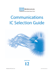
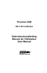
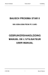
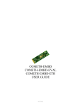
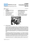
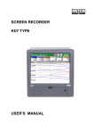
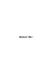
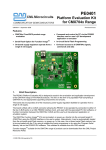
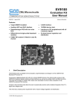
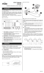
CML Microcircuits COMMUNICATION SEMICONDUCTORS DE8661 V.22bis User Manual for a "socket modem" UM8661/4 June 2004 1.0 Provisional Issue Features • CMX866-based socket modem Reference Design • FCC68 or CTR21 DAA • Fully Isolated 2-Wire Line Interface • Single 3V or 5V dc power supply operation • Opto Isolated Ring Detect Circuitry and OptoMOS Hook Relay • Break-off PCB sections support 'desktop' and 'socket' modem use • Integral AT Command Set with 'Fast Connect' • PCB layout data provided • PC Controlled via Terminal Emulator 1.1 Brief Description The DE8661 Demonstration Board is a reference design for the CMX866 V.22 bis AT command modem IC. The main "socket modem" section contains the CMX866 and associated components in addition to the line interface components. Attached to the main section are two break-off sections which contain a 9pin D type socket for PC serial communications, RJ11 line connector, supply voltage connector and a hook-state LED. The CMX866 contains an on-chip µController, which interprets AT Commands issued via a standard terminal emulator program running on a host PC or via an external µController. Interfacing to the Demonstration Board can be via socket pins on the socket modem section, or via the connectors provided on the break-off sections. The board can be operated at 3V or 5V dc, which must be provided by an external, regulated power supply. The PCB has been laid out for both CTR21 and FCC68 compliant DAA designs. However the components fitted are for the simplified European/FCC68 design. Users wishing to convert to CTR21 should contact CML. 2004 CML Microsystems Plc DE8661 Reference Design and Demonstration Board DE8661 CONTENTS Page Section 1.0 Features ............................................................................................... 1 1.1 Brief Description ................................................................................. 1 1.2 Preliminary Information ...................................................................... 4 1.2.1 Equipment............................................................................... 4 1.2.2 Handling Precautions ............................................................. 4 1.2.3 Approvals ................................................................................ 4 1.3 Quick Start........................................................................................... 5 1.3.1 Setting-Up ............................................................................... 5 1.3.2 Operation ................................................................................ 5 1.4 Signal Lists.......................................................................................... 7 1.5 Circuit Schematics and Board Layout ............................................... 9 1.6 Detailed Description.......................................................................... 11 1.6.1 Hardware Description ........................................................... 11 1.6.2 Serial Interface ...................................................................... 12 1.6.3 Reset Function...................................................................... 13 1.6.4 AT Command and S-Register Summary.............................. 15 1.6.5 General Description of AT Commands................................ 17 1.6.6 Modem Result Codes ........................................................... 18 1.6.7 Terminal Emulator ................................................................ 18 1.7 Performance Specification ............................................................... 20 1.7.1 Electrical Performance ......................................................... 20 2004 CML Microsystems Plc 2 UM8661/4 DE8661 Reference Design and Demonstration Board DE8661 Modem or Telephone Line Simulator J3 J61 DE8661 Power Supply J26/J41 J4 RS232 Cable IBM-PC Figure 1 System Diagram 2004 CML Microsystems Plc 3 UM8661/4 DE8661 Reference Design and Demonstration Board 1.2 Preliminary Information 1.2.1 Equipment DE8661 The following equipment is needed to use this demonstration board: 1.2.1.1 3Vdc or 5Vdc Regulated Power Supply 1.2.1.2 A PC equipped with a serial port running a terminal emulation program such as Microsoft's HyperTerminal. 1.2.2 Handling Precautions 1.2.2.1 Static Protection This product uses low power CMOS circuits, which can be damaged by electrostatic discharge. Partially damaged circuits can function erroneously, leading to misleading results. Observe ESD precautions at all times when handling this product. 1.2.2.2 Contents - Unpacking Please ensure that you have received all of the items on the separate information sheet (EK8661) and notify CML within 7 working days if the delivery is incomplete. 1.2.3 Approvals This product is designed to meet CTR21 or FCC68 telecom approval requirements. Users are advised to observe local statutory requirements which may apply to this product, before direct or indirect connection to any public telecommunication system. 2004 CML Microsystems Plc 4 UM8661/4 DE8661 Reference Design and Demonstration Board 1.3 DE8661 Quick Start This section provides instructions for users who wish to experiment immediately with the demonstration board. A fuller description of the board and its use appears later in this document. 1.3.1 Setting-Up THE DE8661 COMES PRE-CONFIGURED AS AN FCC68 MODEM, USING THE CMX866 D6 28-pin SSOP DEVICE, FOR OPERATION AT 5.0 VOLTS. See section 1.6 for the alternative component values required for 3.0V or CTR21 operation. An RJ11 (US style) phone jack socket, J3, for 2-wire line connection is provided on one of the break-off board sections. Power can be connected via socket pins 61(VDD) and 41(GND) (see figure 2.0, section 1.5), or via jumper JP4 on the break-off section. Attach the 9-way RS232 cable between connector J4 and the serial port of the PC. Connect an external modem/line simulator to the evaluation kit using a suitable RJ11 telephone cable (not supplied). The DE8661 is supplied with the break-off sections of the board intact. If a socket modem using the industry standard footprint is required, detach these break-off sections from the Demonstration Board PCB by using a suitable tool to scribe along the perforations that join the break-off sections to the main PCB. Scribe on both top and bottom sides of the board and ensure that the scribed line completely cuts any copper tracks entering or leaving the break-off sections from the main PCB. When this is done, gently break-off the first section on which connector J4 (9-pin D Type socket) is mounted, then break-off the second section on which the RJ11 socket is mounted. All connections to the remaining socket modem must now be made through the PCB connector pins. 1.3.2 Operation The DE8661 demonstration board allows the user to perform calling, answering and simple data transfer with an external third party modem (not supplied). In order to provide central office/exchange dc line voltage, a suitable central office simulator is also required. The board is controlled by the AT command set described in Section 1.6.4. These commands can be sent to the DE8661 from a terminal emulator program running on a host PC or from an external µController. A suitable emulator is the ‘HyperTerminal’ program, which operates under Windows 95 upwards. The DE8661 AT command set consists of Basic, Extended and CML Specific commands. The board has two modes of operation: AT Command Mode In this mode the CMX866 on-chip AT command processor checks to see if the user has typed a valid AT command. When a valid command is received, it is interpreted then actioned by the CMX866. When operating in this mode, the user can instruct the DE8661 to manually answer a call, originate a call, go on/off hook, read/write to S-registers, issue CML specific AT commands, and perform any number of other AT command functions. The board always starts in AT Command mode after power is applied and board initialisation is complete. The Dial and Answer commands will execute the relevant DTMF transmit, call progress tone detection and negotiation (handshaking) functions before a connection to a remote modem/simulator can be established. Negotiation may be aborted by pushing any key. 2004 CML Microsystems Plc 5 UM8661/4 DE8661 Reference Design and Demonstration Board DE8661 Note: If the S0 register is modified to a non-zero value during this operating mode the CMX866 will poll its status register every 20ms to check for ring detection. If valid ringing is detected the DE8661 will automatically answer a call after n ring cycles, where n is equivalent to the contents of the S0 register. Data Transfer Mode After gaining a connection (i.e. successful negotiation) with a remote modem the board will operate in data transfer mode. In this mode the board will transmit all the data it receives from the RS232 computer terminal or external µController to the remote modem via the 2-wire line. Likewise any data received from the remote modem via the 2-wire line will be sent to the RS232 computer terminal or external µController. Whilst operating in this mode the data stream from the RS232 computer terminal or external µController is monitored for the escape code sequence (+++). If this sequence is encountered during data transfer the board will revert to on-line AT command mode. Whilst in on-line AT command mode, the remote modem connection may be aborted by typing ATH0 (instructs the DE8661 to go on-hook). Alternatively the user can enter relevant AT commands or return to data transfer mode by using the ATO command. The modem line speed is much lower than the speed of the RS232 interface (RS232 is running at 9600bps). To prevent the CMX866 internal data buffer from overflowing, the data flow between the host system and the RS232 interface on the DE8661 is controlled using the CTS (Clear to Send) hardware handshake line. The CMX866 settings used during negotiation and data transfer will be based on the contents of the S-registers when the call was originated or answered. The S-registers are described in Section 1.6.4. Certain S-register settings (relevant to the CMX866 configuration), modified during on-line AT command mode, will only take effect when a new call is originated or answered. For example, new CMX866 Tx gain settings (S25 register) modified in on-line AT command mode will be ignored until the next call. 2004 CML Microsystems Plc 6 UM8661/4 DE8661 Reference Design and Demonstration Board 1.4 DE8661 Signal Lists CONNECTOR PINOUT Connector Ref. Signal Name Signal Type Description J1 TIP Bi Socket pin - Tip J2 RING Bi Socket pin – Ring 3 RING Bi RJ11 connector – Ring 4 TIP Bi RJ11 connector – Tip 1 DCD Output 9-pin D Type connector – Host DCD 2 RXD Output 9-pin D Type connector – Host RXD 3 TXD Input 9-pin D Type connector – Host TXD 4 DTR Input 9-pin D Type connector – Host DTR 5 VSS Power 9-pin D Type connector – Host GND 6 DSR Output 9-pin D Type connector - Host DSR 7 RTS Input 9-pin D Type connector – Host RTS 8 CTS Output 9-pin D Type connector - Host CTS 9 RI Output 9-pin D Type connector – Host RI J24 /RESET Input Socket pin – CMX866 reset J26 VSS Power VSS connection J29 N/C J30 N/C J31 N/C J32 N/C J33 /RTSTTL Input Socket pin – CMX866 RTSN J34 /RXDTTL Output Socket pin – CMX866 RXD J35 /TXDTTL Input Socket pin – CMX866 TXD J36 /RITTL Output Socket pin – CMX866 RIN J37 /DSRTTL Output Socket pin – CMX866 DSRN J38 /CTSTTL Output Socket pin – CMX866 CTSN J39 /DCDTTL Output Socket pin – CMX866 DCDN J40 /DTRTTL Input Socket pin – CMX866 DTRN J41 Vss Power Vss connection J61 VDD Power +ve power from external power supply J62 N/C J63 N/C J3 J4 Connector Pin No. 2004 CML Microsystems Plc 7 UM8661/4 DE8661 Reference Design and Demonstration Board DE8661 LEDs LED Ref. Description D7 Illuminated when the line is in an off-hook state JUMPERS Jumper Ref. Positions Default Position Description JP1 1-2 S/C RS232 Receiver enable (U8) JP4 1-2 O/C Allows a supply voltage to be physically connected to the top side of the PCB. Notes: Bi S/C O/C N/C 2004 CML Microsystems Plc = = = = Bidirectional Short Circuit Open Circuit Not Connected 8 UM8661/4 DE8661 Reference Design and Demonstration Board 1.5 DE8661 Circuit Schematics and Board Layout For clarity circuit schematics are available as separate, high resolution, files. TIP J1 RING J2 J63 N/C J62 N/C J61 VDD J41 GND J40 /DTRTTL J39 /DCDTTL J38 /CTSTTL J37 /DSRTTL J36 /RITTL J35 /TXDTTL J34 /RXDTTL J33 /RTSTTL /RESET J24 GND J26 N/C J29 N/C J30 N/C J31 N/C J32 Figure 2 Socket Section Pinout (topview) 2004 CML Microsystems Plc 9 UM8661/4 DE8661 Reference Design and Demonstration Board DE8661 Figure 3a DE8661 Top Silk Screen Figure 3b DE8661 Bottom Silk Screen 2004 CML Microsystems Plc 10 UM8661/4 DE8661 Reference Design and Demonstration Board 1.6 Detailed Description 1.6.1 Hardware Description DE8661 1.6.1.1 Operating Voltage The DE8661 can be operated at a VDD of 3 or 5Vdc (default), supplied by an external regulated power supply. Tables of component values for CTR21 and FCC68 DAAs are shown below: CTR21 DAA VDD 3.0 V 5.0 V R6 91K (93.5k) 56K (57.6k) R7 160k 180k C24 180pF 220pF FCC68 DAA VDD R6 R7 C24 3.0 V 100K (107k) 160k 39pF 5.0 V 62K (64.9k) 180k 47pF (The values shown in brackets are optimal values) R12 220R 620R D1 3.0V 4.3V R12 220R 620R D1 3.0V 4.3V 1.6.1.2 Clock/Oscillator The CMX866 is clocked at a frequency of 11.0592MHz, which is provided by crystal X1. 1.6.1.3 On-hook Caller ID This function provides a high impedance, on-hook AC path for the routing of Caller ID signals to the CMX868. Components C9, R5 provide this transmission path. C9 bypasses the optoMOS relay hook switch, allowing AC signals to pass through T1 when the socket modem is in an onhook state. The CMX866 has a switched inverting input (pin 11) which is used to compensate for input signal losses incurred while in the on-hook state. 1.6.1.4 Simplified FCC68 Compliant DAA, as Shipped The values of R4, R6, R7, R8, R9, C8 and C24 are optimal values with respect to the Midcom 82111 wet line transformer. Parts C10 and D4 are not required for this simplified design but are replaced with 0Ω links. 1.6.1.5 CTR21 Compliant DAA Components R10, R11, C11, D4, D5, U4 and U5 may be fitted to provide a 60mA current limit required by CTR21. An alternative wet line transformer, the Midcom 82107, must be fitted. Parts C10, C24, and R6 also have different values, to match the characteristics of the 82107 transformer and the CTR21 reference impedance. 2004 CML Microsystems Plc 11 UM8661/4 DE8661 Reference Design and Demonstration Board DE8661 1.6.1.6 Line Protection Line protection is provided by the Sidactor component E1. Sidactor is the trade name for a type of Transient Voltage Suppressor (TVS) manufactured by Teccor Electronics. 1.6.1.7 Ring Detection The ring detect threshold is approximately 20VRMS. 1.6.2 Serial Interface The DE8661 can be controlled by sending AT commands over a direct serial interface from an external µController, or with a standard terminal emulator program running on a host PC, and connected via RS-232. This latter option makes use of the 9-pin D type socket and MAX3237 RS-232 Transceiver chip, both of which are fitted to one of the break-off sections of the DE8661 PCB. Asynchronous communication is used with 9600 baud, 8-bit words, no parity and 1 stop-bit. The 9600 baud rate necessitates CTS flow control to moderate the data rate. The CTS flow control method provided on the CMX866 will also work with the RTS/CTS handshake protocol used by some µControllers. If using an external µController to control the DE8661, its Request To Send signal should be taken low, which takes the CMX866 RTSN pin low. Data is asserted (AT commands or data), by the external µController onto the CMX866 TXD pin. When the DE8661 is ready to accept this data from the external host µController the CMX866 will takes its CTSN pin low. The data should be sent as 8-bit bytes, encapsulated by a start bit (low) and a stop bit (high). The DE8661 should be presented with continuous mark (stop bits) when the external µController has no data to send. As each byte is received it is stored in an on-chip, 48-byte AT command buffer when in Command mode or in an on-chip, 16-byte receive data buffer when in Data Transfer mode. The CMX866 will take its CTSN pin high when either buffer is full and will ignore further information on the TXD pin until the on-chip µController is ready to accept it. At this time, the CMX866 will once again take its CTSN pin low to signify its readiness to accept more data, providing the RTSN pin is already low. If the external µController does not have a Request To Send signal, the RTSN pin should be permanently wired low. When RTSN is inactive high, CTSN follows RTSN and becomes inactive high, thus there is no data flow in either direction between the DE8661 and the external µController. As the incoming AT command is being interpreted, any phone number is identified and stored separately in the 24-byte on-chip phone number buffer. When the DE8661 is in Data Transfer mode and a signal is received from the phone line exceeding the minimum amplitude threshold, the CMX866 will attempt to demodulate the signal and assert the received data on its RXD pin, after a complete byte has been demodulated. At the same time it will take its DCDN pin low. There is a 24-byte message buffer in the CMX866 receive path but, as the received data always arrives at slower than 9600 baud, there is no need for a flow control handshake in the receive path. It is assumed that the external µController will absorb all of the data presented to it without the need for flow control and will ignore continuous mark (stop bits) when there is no received data. If the received signal is below the detection threshold or the DE8661 is not in Data Transfer mode, the CMX866 will take its DCDN and RXD pins high. If the CMX866 receives a RING signal on the RD and RT pins, such that the detection threshold is exceeded, then this condition will be signalled to the external µController by the CMX866 taking its RIN pin low. This pin follows the output of the ring detector, so will go low for each burst of RING signal. If the CMX866 is in a Powersave or 'Zero-Power' state, it will be woken up and the DSRN pin will go low once the on-chip µController is ready to receive communications through the serial port. This wake up process takes about 30ms from 'Zero-Power' state, as the VBIAS pin has to charge the external reservoir capacitor and the crystal oscillator has to start up 2004 CML Microsystems Plc 12 UM8661/4 DE8661 Reference Design and Demonstration Board DE8661 and stabilise before the CMX866 can initialise itself. From the Powersave state this wake up process takes about 10µs, as the oscillator and the VBIAS pin are already stable. The CMX866 DSRN and DTRN pins do not act as a handshake with the external µController. The DSRN pin indicates the operational status of the on-chip µController (low = ready to communicate with an external µController). The DTRN pin is used for taking the CMX866 out of Powersave or 'Zero-Power' state. It effectively acts as a device wake up, in the same manner as the RING signal, and becomes active on the high to low transition. A high to low transition on the DTRN pin is ignored if the device is already 'woken up'. If the external µController does not have a DTR signal, the DTRN pin should be permanently wired to the TXD pin. When the CMX866 is in a Powersave or 'Zero-Power' state, the RXD, CTSN, DSRN, DCDN and RIN pins will be permanently high. The condition of the TXD, RTSN and DTRN pins is not important. Depending on the &Dn configuration, if the DTRN pin on the CMX866 is taken high at any time whilst the DE8661 is in Data Transfer mode, a fixed, 100ms timeout is started. On completion of the timeout, the DE8661 will return to AT Command mode, enabling further AT commands to be sent. If the DTRN pin goes high whilst the DE8661 is in AT Command mode, the action is ignored. AT commands can be sent providing CTSN and RTSN are low (ie DTRN can be either high or low). A low to high transition on the ESC pin also has the same effect of returning the DE8661 from Data Transfer mode to Command mode, but with immediate effect. The &Dn command configures these options, see section 1.5.4.4 for more details. If the RTSN pin of the CMX866 is taken high at any time whilst the DE8661 is in Data Transfer mode, a timeout is started whose value is set in the S28 register (0 = timeout disabled). On completion of the timeout, the DE8661 will return to AT Command mode and take CTSN high. If the RTSN pin goes high whilst the DE8661 is in AT Command mode, the CTSN pin goes high and the action on the RTSN pin is ignored. Information transfer can only restart when the RTSN pin is taken low again and the CMX866 responds by taking CTSN low. 1.6.3 Reset Function The CMX866 as fitted to the DE8661 has an internal power-up reset function which is activated whenever power is applied to the board. This reset function resets all of the on-chip µController registers, including the S-Register settings, and then performs an initialisation sequence which resets the internal DSP and subsequently places it in a powersave state, loads the factory default values into the S-Registers and places the on-chip µController into an operating state. This internal power-up reset function is OR-ed with the RESETN pin. When the RESETN pin is taken low, i.e. SW1 on the break-off section is activated or a low signal is applied to pin 24 of the DE8661 the reset operation described above is performed. When the CMX866 first enters the operating state, it reports its configuration as follows: • CMX866 waits for DTRN to go active (low) - to wake up the device • CMX866 takes the DSRN pin active (low) to indicate its readiness to communicate with an external µController • CMX866 waits for RTSN to go active (low) • CMX866 sends "CMX866" identification message to external µController (equivalent to the external µController issuing an ATI0 command) • The on-chip µController now powers up the DSP part of the CMX866 • The DSP is automatically reset then requested to perform an internal diagnostic self-check, which takes about 2.9ms to complete • On successful completion, CMX866 sends "DSP checksum OK" identification message to the external µController. If not successful, CMX866 sends "DSP Error" message to the 2004 CML Microsystems Plc 13 UM8661/4 DE8661 Reference Design and Demonstration Board DE8661 external µController. In the latter case, the CMX866 should be reset again by taking the RESETN pin low • The on-chip µController now powers down the DSP part of the CMX866 • The on-chip µController is now in the Command mode operating state and is ready to accept AT commands from the serial interface, approximately 55ms after DTRN goes low • CMX866 takes the CTSN pin active (low) to indicate its readiness to communicate with an external µController 2004 CML Microsystems Plc 14 UM8661/4 DE8661 Reference Design and Demonstration Board 1.6.4 DE8661 AT Command and S-Register Summary AT Command Parameters Function A Answer Command - Answer and establish a connection when off-hook A/ Re-execute last command Select Communications Standard (Mapped to S27) Bn Dn ... n or DTn ... n n = 0 V.22bis 2400bps QAM n = 1 V.22 1200bps DPSK n = 2 V.23 Tx 75bps, Rx 1200bps (Master) n = 0..9 n = 3 V.23 Tx 1200bps, Rx 75bps(Slave) n = 4 Reserved n = 5 V.21 300bps FSK n = 6 Bell 212A 1200bps DPSK n = 7 Bell 202 Tx 150bps Rx 1200bps n = 8 Bell 202 Tx 1200bps Rx 150bps n = 9 Bell 103 300bps FSK n = 0..9, A..D, *,# Dial Command - DTMF dials the subsequent Directory Number , Dial Command Modifier - Delay during dialling - time in S8 register ! Dial Command Modifier- Send a line break - time in S29 register ; Dial Command Modifier - command mode after dialling, no handshake DL Default n=0 Dial Command - Redial last number En n = 0,1 Command echo, 0=off, 1=on n=1 Hn n = 0,1 Switch Hook Control, 0=on-hook, 1=off-hook n=0 In n=0 Nn n = 0,1 O Qn Identification - Returns the modem's product identification V.22bis Fallback to V.22 option, 0=none, 1=automatic Go online in Data mode (from Command mode) n = 0,1 RO Enable(n=0)/Disable(n=1) return of modem result codes Execute V.23 or Bell 202 turnaround if enabled (see S14 and S24) then go online in Data mode Function AT Command Parameters Sn? n = 0..29 S-Register "n" Read - Display specified S Register contents Sn=x Vn Xn n = 0..29 n =0,1 n = 0..3 S-Register "n" Write - Write to specified S Register Return result codes as numbers (n=0) or words (n=1) Calling and Response Characteristics Z &Cn n=1 n=0 Default n=0 n=3 Restore factory profile for CMX866 n = 0,1 &Dn n= 0..2 &Gn &Tn n = 0..2 n = 0,3..6 DCD always on (n=0) or DCD follows carrier (n=1) n=1 DTR signal procedure n=2 Guard Tone Select - Disable (n=0), Enable 550Hz (n=1) or 1800Hz (n=2) User accessible Loopback Tests and Diagnostics n=0 n=0 Returns current configuration &V 'Zero-Power' state (n=0) or Powersave state (n=1) &Zn n = 0,1 @Rn? n = 00..FF DSP Register "n" Read - Display specified DSP Register contents @Rn=x n = 00..FF DSP Register "n" Write - Write to specified DSP Register 2004 CML Microsystems Plc 15 UM8661/4 DE8661 Reference Design and Demonstration Board S Registers DE8661 Parameters Function S0 0…255 Number of rings before answering, 0 = Auto-answer disabled S1 0…255 Number of rings received Default 2 0 S2 0-127 Escape character value S3 0-127 Carriage return character value + S4 0-127 Line feed character value LF S5 0-127 Backspace character value BS S6 2…255 Waiting time in seconds for dial tone or before blind dialling 4s S7 2…255 Maximum waiting time in seconds for carrier 50s S8 0...255 Pause time in seconds for "," dial modifier 2s S9 1...255 Reserved CR S10 1…255 Lost carrier to hang up delay in units of 100ms 700ms S11 5…255 DTMF tone duration and interdigit pause duration in units of 10ms 100ms S12 0…255 Escape code guard time in units of 50ms 0…255 General Options: bypass Answer Tone Detect sequence for 'Fast Connect' S13 S14 1s Reserved $92 S15 0…255 Loopback carrier off time in milliseconds 80ms S16 0…255 Drop time for loopback in milliseconds 60ms S17 0…255 Handshake timeout (Answering) in seconds 30s S18 0…255 Loopback timer (0= no timeout) in seconds 0s S19 Reserved for test functions S20 Reserved S21 0…255 Loopback and Power states $10 S22 0…255 Calling and response characteristics selection $C0 S Registers Parameters S23 0…255 Guard tone selection S24 0…255 Equaliser, DCD, DTR status and modulation fallback $A9 S25 0…255 Tx Gain, Tx data format $B0 S26 0…255 Rx Gain, Rx data format, overspeed (2.3% default) setting $30 S27 0…255 Communications Protocol $00 S28 0…255 RTSN Timeout for return to Command mode from Data mode in seconds 0s S29 0…255 Timed Break Recall period in centiseconds Xn Register Parameter n 0 Function Default $00 300ms Calling and Response Characteristics (Mapped to S22 register) 1 Ignore dial tones and busy tones, return CONNECTxxxx or NO CARRIER Ignore busy tone, wait for dial tone to dial. Return NO DIAL TONE or CONNECT xxxx or NO CARRIER 2 Ignore dial tone. If busy tone detected, return BUSY. Return CONNECT xxxx 3 Return NO DIAL TONE, BUSY, CONNECT xxxx, or NO CARRIER 2004 CML Microsystems Plc 16 UM8661/4 DE8661 Reference Design and Demonstration Board &Dn Register Parameter DTR action n (Mapped to S24 register) 0 &Gn Register Ignore DTR signal 1 Go to command state when on to off transition occurs 2 Hang up and go to command state when on to off transition occurs Parameter Guard Tone action n &Tn Register 1.6.5 DE8661 (Mapped to S23 register) 0 Disabled 1 Enabled 550Hz 2 Enabled 1800Hz Parameter Test function n 0 (Mapped to S21 register) Terminate test 1 Reserved 2 Reserved 3 Local digital loopback 4 Enable remote request for digital loopback 5 Disable remote request for digital loopback 6 Request remote digital loopback & initiate General Description of AT Commands Supported AT commands are listed in section 1.6.4. Valid commands will generate an 'OK' result code (see section 1.6.6) and invalid commands will be rejected with an 'ERROR' result code, when command echoing and word result codes are enabled. The CMX866 will send a <LF> character directly after a <CR> character to ensure compatibility with external µControllers. Any commands which are not fully implemented will return the result code ‘NYI’ (Not Yet Implemented). AT commands should not be sent to the on-chip µController until the previous result code (if enabled) has been received. Each command line (except for A/ and the escape sequence) must begin with the AT prefix and be terminated with a carriage return <CR>. The CMX866 waits to receive a complete AT command line before processing it. Embedded spaces are ignored and the case (upper or lower) of characters including the ‘AT’ does not matter. The command line must not exceed 48 characters (excluding the ‘AT’ characters). The CMX866 will ignore the command line and return an 'ERROR' result code if the line is not terminated correctly. All characters in the AT command, including the ‘AT’ and <CR> terminator are echoed (if E1 is set) by the DE8661 in the order in which they are sent by the external µController. If when entering an AT command, no command or register name suffix is supplied, a suffix of zero is assumed. If when changing a register value, no value is supplied a value of zero or an empty string is assumed, i.e. ATS0=<CR> is equivalent to ATS0=0<CR>. 2004 CML Microsystems Plc 17 UM8661/4 DE8661 Reference Design and Demonstration Board DE8661 Receipt of a back space will cause the DE8661 to send a "backspace, space, backspace" sequence of characters to the external µController, to allow any terminal which may be connected to the latter to clear its screen of the last character. Also the last character received will be discarded unless the last characters received were ‘AT’, ie the ‘AT’ is never deleted. The escape sequence ‘+++’ (with Guard Time = 1s [see S12 register] before and after the sequence) will cause the DE8661 to enter AT Command mode from Data Transfer mode and to return an ‘OK’ response. A detailed description of AT commands and S-Registers can be found in the CMX866 Data Sheet, available from the CML website. 1.6.6 Modem Result Codes Numeric Response (Decimal) 00 01 02 03 04 05 06 07 08 09 10 11 12 13 14 15 1.6.7 Alpha Response OK CONNECT RING NO CARRIER ERROR NO DIAL TONE BUSY CONNECT 2400 CONNECT 1200 DUAL TONE DETECT CONNECT 300 CONNECT 1200/75 CONNECT 75/1200 CONNECT 1200/150 CONNECT 150/1200 NYI (Not Yet Implemented) Terminal Emulator If using a terminal emulator to control the DE8661, ‘HyperTerminal’, which is supplied with the Windows 95/NT installations, is suitable for this purpose. HyperTerminal Setup Emulation VT100 ASCII Character set ASCII Receiving: COM Port Settings: Wrap lines that exceed terminal width. Bits per second Data bits Parity Stop bits Flow Control 9600 8 None 1 Hardware Some terminal emulators have been found not to support full hardware flow control when transferring text files. This could result in data loss when using this facility. If this problem is experienced users should try using a different terminal emulator. 2004 CML Microsystems Plc 18 UM8661/4 DE8661 Reference Design and Demonstration Board DE8661 To ensure successful negotiation and data transfer between the DE8661 and third party modems, users should ensure their third party modem is configured to the correct protocol (see third party AT command documentation). Note, any sudden loss of the 2-wire line during data transfer will result in loss of carrier and therefore the demonstration board will hang up and display the NO CARRIER message. However, due to the lost carrier to hang up delay (S10), a short burst of corrupt characters (noise generated) will be observed on the HyperTerminal window before the NO CARRIER message is displayed. These corrupt characters can sometimes match control characters and therefore modify HyperTerminal’s behaviour. The user is advised to restart HyperTerminal if this happens. 2004 CML Microsystems Plc 19 UM8661/4 DE8661 Reference Design and Demonstration Board 1.7 Performance Specification 1.7.1 Electrical Performance DE8661 1.7.1.1 Absolute Maximum Ratings Exceeding these maximum ratings can result in damage to the DE8661. Min. -0.3 -0.3 -20 Supply (VDD – VSS) Voltage on any connector pin to VSS Current into or out of any socket modem connector pin other than VDD, VSS, TIP and RING Max. 7.0 VDD + 0.3 +20 Units V V mA Max. 5.5 Units V 1.7.1.2 Operating Limits Correct operation of the DE8661 outside these limits is not implied. Notes Supply (VDD – VSS) Min. 2.7 1.7.1.3 Operating Characteristics For the following conditions unless otherwise specified: Evaluation Device Xtal Frequency = 11.0592MHz ±0.01% (100ppm) VDD = 3.0V or 5.0V, Tamb = +25°C. Notes DC Parameters IDD (socket modem alone - idle) IDD (demonstration board - idle) Notes: 1. 2004 CML Microsystems Plc 1 Min. Typ. 10 18 Max. Units mA mA Hook LED off 20 UM8661/4 DE8661 Reference Design and Demonstration Board DE8661 CML does not assume any responsibility for the use of any circuitry described. No IPR or circuit patent licences are implied. CML reserves the right at any time without notice to change the said circuitry and any part of this product specification. Evaluation kits and demonstration boards are supplied for the sole purpose of demonstrating the operation of CML products and are supplied without warranty. They are intended for use in a laboratory environment only and are not for re-sale, end-use or incorporation into other equipments. Operation of these kits and boards outside a laboratory environment is not permitted within the European Community. All software/firmware is supplied "as is" and is without warranty. It forms part of the product supplied and is licensed for use only with this product, for the purpose of demonstrating the operation of CML products. Whilst all reasonable efforts are made to ensure that software/firmware contained in this product is virus free, CML accepts no resonsibility whatsoever for any contamination which results from using this product and the onus for checking that the software/firmware is virus free is placed on the purchaser of this evaluation kit or development board. www.cmlmicro.com For FAQs see: www.cmlmicro.com/products/faqs/ For a full data sheet listing see: www.cmlmicro.com/products/datasheets/download.htm For detailed application notes: www.cmlmicro.com/products/applications/ CML Microcircuits (UK) Ltd &20081,&$7,21 6(0,&21'8&7256 CML Microcircuits (USA) Inc. CML Microcircuits (Singapore)Pte Ltd &20081,&$7,21 6(0,&21'8&7256 Oval Park, Langford, Maldon, Essex, CM9 6WG - England. 4800 Bethania Station Road, Winston-Salem, NC 27105 - USA. No 2 Kallang Pudding Road, #09 - 05/06 Mactech Industrial Building, Singapore 349307 No. 218, Tian Mu Road West, Tower 1, Unit 1008, Shanghai Kerry Everbright City, Zhabei, Shanghai 200070, China. Tel: +44 (0)1621 875500 Tel: +65 6745 0426 Fax: +44 (0)1621 875600 Tel: +1 336 744 5050, 800 638 5577 Fax: +1 336 744 5054 Fax: +65 6745 2917 Tel: +86 21 6317 4107 +86 21 6317 8916 Fax: +86 21 6317 0243 Sales: [email protected] Sales: [email protected] Sales: [email protected] Sales: [email protected] Technical Support: [email protected] Technical Support: [email protected] Technical Support: [email protected] Technical Support: [email protected]