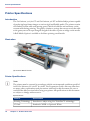
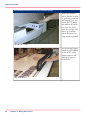
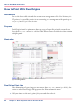
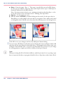
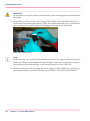
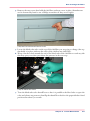
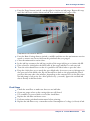
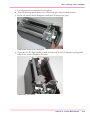
1
Océ User Manual
Océ Arizona 300/360 GT & XT
User Manual, Océ Arizona 360, Revision B
Copyright
© 2011 Océ
All rights reserved. No part of this work may be reproduced, copied, adapted, or transmitted
in any form or by any means without written permission from Océ.
Océ makes no representation or warranties with respect to the contents hereof and specifically disclaims any implied warranties of merchantability or fitness for any particular purpose.
Further, Océ reserves the right to revise this publication and to make changes from time
to time in the content hereof without obligation to notify any person of such revision or
changes.
Edition: 2011 #3010111801
Contents
Contents
Chapter 1
Introduction.........................................................................................................7
Preface.........................................................................................................8
Product Compliance.................................................................................11
Chapter 2
Product Overview.............................................................................................15
Printer Specifications...............................................................................16
Chapter 3
Safety Information............................................................................................19
UV Ink and Flush.......................................................................................20
UV Curing System ...................................................................................21
Safety Interlock System...........................................................................23
Océ Arizona 300/360 GT Safety Labels...................................................24
Safety Awareness.....................................................................................28
Roll Media Safety Awareness.................................................................37
Chapter 4
How to Navigate the User Interface...............................................................39
Operator Interface Hardware...................................................................40
Printer Interface Software........................................................................42
Print Job Control Module........................................................................44
Counters Module......................................................................................53
Settings Module.......................................................................................54
Tools and Utilities Module......................................................................59
Installation and Upgrade Module...........................................................64
Chapter 5
How to Operate Your Océ Arizona Printer.....................................................65
Training Requirements............................................................................66
How to Power the Printer On and Off.....................................................67
How to Install the Onyx Printer Driver....................................................72
How to Manage Print Jobs......................................................................75
Daily Start-up and Shut-down...........................................................75
How to Set Up a Print Job.................................................................76
How to Manage the Media Vacuum.......................................................80
The Media Vacuum System...............................................................80
Common Custom Vacuum Zones.....................................................83
How to Manage Media.............................................................................86
How to Handle Media.........................................................................86
3
Contents
Chapter 6
How to Operate the Océ Arizona 360 XT.......................................................91
Océ Arizona 360 XT Features..................................................................92
How to Use the Océ Arizona 360 XT Vacuum System..........................94
How to Print With Dual Origins...............................................................96
Chapter 7
How to Operate the Roll Media Option..........................................................99
Roll Media Option Hardware.................................................................100
Roll Media Option Specifications..........................................................102
Foot Pedal Switch Functions.................................................................104
Roll Media Manager...............................................................................105
How to Load Media................................................................................107
How to Unload and Cut Media..............................................................117
How to Set Up a Roll Media Job in ProductionHouse........................119
How to Print on Roll Media ..................................................................121
How to Determine the Media Advance Correction Factor..................125
How to Use Media Edge Protectors......................................................127
Chapter 8
How to Use the Static Suppression Upgrade Kit........................................131
Reduce Static with a Static Suppression Kit .......................................132
Chapter 9
How to Work With White Ink.........................................................................135
Operator Guidelines for White Ink........................................................136
White Ink Workflow Overview...............................................................137
How to Configure ProductionHouse for White Ink..............................140
QuickStart................................................................................................142
How to Prepare White Ink Print Jobs....................................................144
How to Create a White Flood Fill Layer..........................................144
How to Create Spot Data with the Spot Layer Tool.......................146
How to Create White Spot Data in Photoshop...............................150
How to Create White Spot Data in Illustrator.................................155
How to Print With White Ink..................................................................167
How to Use Media Models..............................................................167
How to Create a Media for White Ink Print Jobs............................176
How to Create and Use Quick Sets.................................................189
Chapter 10
Ink System Management...............................................................................193
Arizona Printer Inks................................................................................194
How to Change Ink Bags........................................................................198
Chapter 11
Error Handling and Troubleshooting............................................................201
Troubleshooting Overview....................................................................202
4
Contents
How To Improve Quality When Banding Occurs.................................204
Chapter 12
Printer Maintenance.......................................................................................205
Maintenance Guidelines........................................................................206
Maintenance Procedures.......................................................................208
Clean Carriage Underside................................................................208
Printhead Maintenance....................................................................211
Swab Printheads...............................................................................218
How to Clean the UV Lamp Filter....................................................222
How to Remove Ink..........................................................................224
Empty the Ink Waste Tray................................................................226
Fill the Coolant Reservoir ................................................................228
Replace the Spit Catcher Foam Pad................................................231
Clean Gantry Rails............................................................................233
How to Change Ink Filters................................................................235
How to Change a UV Lamp Bulb.....................................................240
How to Maintain White Ink..............................................................247
Roll Media Option Maintenance...........................................................249
RMO Maintenance Guidelines.........................................................249
How to Clean the Rubber Capstan..................................................250
Appendix A
Application Information.................................................................................255
Application Resources on the Web Site...............................................256
5
Contents
6
Chapter 1
Introduction
Preface
Preface
Introduction
This manual provides the operator with information about the following Océ UV flatbed
inkjet printers:
■
■
■
Océ Arizona® 300 GT
Océ Arizona® 360 GT
Océ Arizona® 360 XT
The operational features of these printer models are similar with the following exceptions:
the 300 GT has four sets of printheads; the 360 GT and 360 XT have eight sets (ten with
the white ink option). The main difference in function is the actual speed due to the lack
of Express mode and less printheads in the 300 GT. The 360 XT has a larger table than
the other models. The manual uses the terms Océ Arizona 300/360 GT or Océ Arizona
360 XT to refer to these printers. The manual orients you to the many features and procedures that allow you to print professional quality images on various media with these
printers.
Multi-Language Support
The printer's user interface software supports multiple languages. To select your preferred
language and other setup information, refer to the Settings Module in Chapter 4.
This manual is also available in other languages. Printers are shipped with a printed copy
of the US English version. You can download a PDF file of the manual in all of the languages that we support from the Customer Support web site: http://dgs.oce.com/
Supported languages:
■
■
■
■
■
■
8
English
Dutch
German
French
Spanish
Italian
Chapter 1 - Introduction
Preface
Océ DGS on the Internet
For further information on documentation and support for your printer or for information
on other Océ Display Graphics Systems products, please visit our web site:
http://www.dgs.oce.com
To provide feedback and report errors in this document: [email protected]
Safety Information
This manual has three sections that contain details on safety when handling ink and using
the printer. Also, where applicable, cautions and warnings are used throughout this
manual to draw your attention to safety precautions.
■
■
■
"Safety Guidelines for Ink Materials" offers advice in the proper handling of UV inks;
"Interlock Safety System" explains the safety features built in to the printer that prevent
and minimize access to Mechanical, Electrical, Thermal and UV hazards; and
"UV Curing System Safety" presents warning about the dangers of exposure to UV
light. Some of the material from that section are duplicated here.
Customer Service
If your printer malfunctions and you are unable to resolve the problem, field service
technicians can be dispatched to your site to conduct repairs. Service visits are paid for
by the customer, either under a maintenance agreement, by purchase order or prepayment.
Time and material rates are charged for any service not covered under a maintenance
agreement. Before calling to report a problem, gather as much information about the
problem as possible and have it ready to provide to your customer care center. The more
information you can provide initially, the more quickly the problem can be corrected.
Statement of Foreseen Use
The Océ Arizona flatbed inkjet printers are intended for use in a commercial printshop
environment. Factory-authorized training is made available for operators at the time of
installation. The printers use piezo printing technology and UV curable inks to produce
outdoor-durable output. They can print directly onto rigid and flexible media of up to
48 mm (1.89 inch) thickness. The printer holds the media stationary while the printhead
assembly moves across to create the print, eliminating image skew problems often associated with rigid stock feed systems. With the Roll Media Option installed the printers can
also print on various roll media. See your local representative or visit the Océ Media
Guide for more details on recommended media.
http://mediaguide.oce.com/
Responsibilities of the Operator
The printer operator must be properly trained. Océ provides training for the operator in
the use of the printer hardware and software at the time of installation. It is the customer's
responsibility to ensure that only properly trained personnel operate the printer. Operators
must be fully versed in the operation of ONYX ProductionHouse® . For any operator
unfamiliar with its operation, ONYX ProductionHouse® training is required. Training
courses are available; contact your local Océ representative.
Chapter 1 - Introduction
9
Preface
The operator or other trained personnel are expected to handle all user maintenance as
detailed in the User Manual, and also replacement of consumable parts (except print
heads). If your site has a technician in charge of printer maintenance, that person is the
optimal candidate. While any trained operator may perform routine maintenance, the
best maintenance results from familiarity with the printer's internal operation and history.
The printer requires daily printhead maintenance to ensure the highest print quality and
longer life for the printheads. The printer design provides you easy access to perform this
simple task and it is essential that printhead maintenance is performed at least once a day,
and more frequently if needed. Periodic cleaning must be scheduled for some components
on a regular basis. A few minutes spent cleaning also helps to ensure optimal printer
function and the highest quality prints.
It is the responsibility of the operator to try to eliminate simple problems before calling
a service representative. But knowing when to call for service is also important. An untrained operator must not attempt to service the printer as this may cause further damage.
When you have determined that a service call is required, call as soon as possible. See the
Troubleshooting and Maintenance sections for more details.
Responsibilities of the Service Technician
Field service technicians must have Océ Display Graphics Systems service training. The
service technician is responsible for all repairs, upgrading and modification requested by
the customer or mandated by the Océ Display Graphics Systems Service and Support
Group. The service technician who installs the printer will also provide training for the
operator that covers all of the basic skills required to operate the printer. Service personnel
are furnished with proper tools for the installation and maintenance of the printer. In
addition to the tools and custom kits, each engineer will have basic tools for proper
maintenance and servicing.
10
Chapter 1 - Introduction
Product Compliance
Product Compliance
Introduction
This section provides the EMC FCC compliance information and points to the DGS
web site for access to the official documents for all agency compliance standards that the
Océ Arizona 300/360 GT and Océ Arizona 360 XT conform to. It also provides printer
manufacturing and contact information and a list of any toxic or hazardous material in
the printer.
Electromagnetic Compliance (EMC)
FCC Statement for Class A Device:
This equipment generates, uses and radiates radio frequency energy and if not installed
and used as designed or intended, may cause interference to radio communications. This
equipment has been tested and found to comply with the limits for a Class A computing
device. This equipment has been designed to provide reasonable protection against such
interference when operated in residential and commercial environments. Operation of
this equipment in a residential area may cause interference, in which case the user, at his
own expense, is required to take whatever measures are required to correct the interference.
FCC Notice: This device complies with Part 15 of the FCC Rules.
Operation is subject to the following two conditions:
1) This device may not cause harmful interference, and
2) This device must accept any interference received, including interference that may
cause undesired operation.
Any change or modification not expressly approved by the manufacturer
could void the user's authority to operate the equipment.
This device contains an intentional radiator (RFID)
Radio Certificate Number: IC:6497A-3010105668
FCC Identifier: U2P-3010105668
Product Safety
CE Declaration documents are provided for your convenience. These documents and
other applicable compliance certificates are available for download from the Arizona
Customer Support section of our web site: http://dgs.oce.com/.
Chapter 1 - Introduction
11
Product Compliance
[1] CE Declaration
Noise Measurement Test Summary
Tested according to EN13023:2003, EN11204, ISO3744:1994(E)/ISO3746:1995(E)
and declared according to ISO4871:1984(E)
Measurements taken at the sample in 5 different locations, Printer in normal operation
with Vacuum Pump, does not exceed 75dB (maximum measured value: 66dB). For all
locations, provide noise protection enclosure or remove pump from location.
12
Chapter 1 - Introduction
Product Compliance
Manufacturer:
Océ Display Graphics Systems (ODGS)
13231 Delf Place - Building #501
Richmond, British Columbia
Canada V6V 2C3
Telephone +1 604)273-7730 - Fax +1 604 273-2775
E-mail: [email protected]
Representative Marketing the Océ Arizona 300/360 GT in Europe:
Océ Technologies B.V.
St. Urbanusweg 43,
Venlo, The Netherlands, 5900 MA Venlo
Telephone: 31 77 359 2222
Fax: 31 77 354 4700
E-mail: [email protected]
Toxic and Hazardous Substances or Elements in the Product
#
Part
Name
Lead
(pb)
Mercury
(Hg)
Cadmium (Cd)
Hexavalent
(CrVI)
Polybromiated
biphenyls
(PBB)
Polybrominated
dipenylether
(PBDE)
UV Curing
Lamps
No
Yes
No
No
No
No
VGA
Monitor
No
Yes
No
No
No
No
Vacuum
Guage
Indicator
Yes
No
No
No
No
No
Linear
Encoder
Readheads
Yes
No
No
No
No
No
Printheads
Yes
No
No
No
No
No
Yes indicates that the substance is present in that printer component.
No indicates that the substance is NOT present in that printer component.
Chapter 1 - Introduction
13
Product Compliance
14
Chapter 1 - Introduction
Chapter 2
Product Overview
Printer Specifications
Printer Specifications
Introduction
The Océ Arizona 300/360 GT and Océ Arizona 360 XT are flatbed inkjet printers capable
of producing large format images on various rigid and flexible media. The printers consist
of a flatbed vacuum table and moving gantry. Media is held flat and stationary on the
vacuum table during printing. The gantry contains a carriage that sweeps across the table
as the gantry moves in steps along the length of the table to print an image on the media.
A Roll Media Option is available to facilitate printing onroll media.
Illustration
[2] Arizona 360 GT Printer
Printer Specifications
Note:
The printer must be operated in accordance with the environmental conditions specified
in the Océ Arizona 300/360GT & 360XT Site Preparation Guide. Also note that there
are many safety requirements and precautions indicated in this document. Be sure to
read all of the safety sections before using your printer. All specifications in this document
are subject to change without notice.
Specifications#
16
Feature
Specification
Printing Technology
Piezoelectric inkjet using Océ VariaDot™ technology:
UV Ink
Standard: CMYK or Optional: White.
Chapter 2 - Product Overview
Printer Specifications
Feature
Specification
Maximum Media Size
300/360 GT: 2.5m (98.4") x 1.25m (49.2")
360 XT: 2.5m (98.4") x 3.05m (120.1")
Media Thickness
Maximum: 48mm (1.890")
Maximum Print Size
300/360 GT: 2.51m (98.8") x 1.26m (49.6")
360 XT: 2.51m (98.8") x 3.06m (120.5")
Media Weight
Maximum: 34 kg/m² (7 lbs/ft²)
Nozzle Drop Volume:
Variable droplet sizes from 6 to 42 picolitres
User Interface
LCD flat-panel monitor and mouse on a user-positioned
podium.
Curing System
UV curing lamps with variable power settings.
Power Requirements
Voltage:
(Rated Current: 16A)
208 through 240VAC ±10% 60Hz Single Phase
200 through 240VAC ±10% 50Hz Single Phase
300/360GT: 2 AC lines -16A Inlet 1 and 8A Inlet 2
360XT: 2 AC lines -16A Inlet 1 and 16A Inlet 2
Recommended Circuit Breaker:
North America 20A, European Union 16A.
BTU Output
10,000 BTU (2950 watts) under continuous operation.
Hardware Interface
USB, Ethernet TCP/IP, 100 base-T (or Gigabyte, if supported by the local network).
Image Processing
Software
ONYX® ProductionHouse Océ Edition version 7 or greater
(ONYX® PosterShop is available but not recommended).
The drivers for your printer are included in the ProductionHouse Océ edition, but not in the PosterShop Océ edition.
Chapter 2 - Product Overview
17
Printer Specifications
18
Chapter 2 - Product Overview
Chapter 3
Safety Information
UV Ink and Flush
UV Ink and Flush
Introduction
The safety concerns involved with the handling and use of the UV ink and Flush are detailed in the Material Safety Data Sheet (MSDS) documents. Review them before handling
any UV ink and flush.
Note:
The MSDS for all UV inks and Flush are available from the Customer Support section
of the ODGS web site: http://dgs.oce.com/.
Caution:
UV inks can be harmful if not properly handled. Follow the MSDS guidelines carefully
in order to ensure maximum safety.
Personal Safety
The operator must wear nitrile gloves, a protective apron, and safety glasses with side
shields when handling inks. Read and practice safety guidelines as outlined in the MSDS
for each ink. Post these documents in the work area as required by prevailing law. MSDS
are provided with all inks and flush when you purchase them.
Disposal of UV Ink
All waste containing uncured or partly cured UV ink is hazardous and must be disposed
of separately according to local regulations. Do not mix ink waste with non-hazardous
waste (household, office, etc.). Do not allow it to reach sewage systems or drinking water
supplies. Ink waste includes maintenance pads and cloths, gloves and any other material
containing uncured or partly cured UV ink.
Disposal must be made according to official local regulations.
20
Chapter 3 - Safety Information
UV Curing System
UV Curing System
Introduction
UV-curable ink need a high energy level of UV light to cure. The UV curing system is
made up of two mercury arc lamps attached to the carriage.
How to Handle UV Lamp: UV lamps operate at high temperatures. Never touch a lamp
in operation. Let the lamps cool for a minimum of five minutes before attempting any
maintenance. Use extreme care in handling the UV lamp bulbs. The UV bulbs contain
a small amount of metallic mercury which is toxic when ingested, handled, or breathed.
Therefore, if bulbs are broken, care should be taken to clean up the spill immediately,
and then disposed of according to local regulations concerning Mercury disposal.
Bare skin contact with the UV lamp bulbs must be avoided. When heated, compounds
from the skin can form permanent etching on the surface of the UV bulb. A contaminated
bulb may fail prematurely.
Ozone: As a UV lamp warms up, it briefly passes through a section of the light spectrum
which excites oxygen molecules enough to create ozone. Once a UV lamp has completely
warmed up, only very minute amounts of ozone are present.
Note:
A high concentration of ozone can cause irritation, headaches or nausea. Provide adequate
ventilation as indicated in the Site Preparation Guide.
Caution:
Warning for Seated Individuals: UV emissions are highest at a height of 90 cm (35
inches) above the floor. This can be an issue for individuals seated near the printer.Remove
all chairs within 5 meters (16 feet) of the printer.
Attention:
The UV Lamps contain Mercury. Dispose according to local environmental regulations.
Personal Safety
UV Light Emissions can be harmful:
Protective measures are essential in the workplace. Use the UV safety glasses with side
shields supplied with the printer. Wear appropriate clothing that protects the skin from
UV light exposure. Keep a distance of at least 1 m (3 ft) from UV lamps while printing.
Chapter 3 - Safety Information
21
UV Curing System
Note:
Wear Industrial Protective Eyewear with lenses that block both UVA and UVB. Gloves
and long-sleeved work clothes are essential to reduce the skin's exposure to UV emissions.
22
Chapter 3 - Safety Information
Safety Interlock System
Safety Interlock System
Introduction
The printer has three Emergency-Stop buttons. The Maintenance Station drawer and
the Carriage Guard are also part of the safety interlock system. A beacon light indicates
the status of the safety system and the printer.
Components of the Interlock System
Emergency Stop Buttons:
They are located on the Operator Control Station, and on each end of the Gantry. Activating an Emergency-Stop button stops all printer motion and turns off the UV curing
system.
To re-activate the printer after you press an Emergency Stop button, turn the button
counter-clockwise. Upon release of the button, no motion can be initiated without acknowledgment of the Operator from the Control Station.
Maintenance Station Interlock Function:
The Maintenance Station is located under the carriage and provides access to perform
Printhead Maintenance and swab printheads. Carriage and Gantry motion motors are
disabled and UV lamps are turned off (if they were On), when the station drawer is open.
The Interlock system is automatically reset when the drawer is closed.
Carriage Guard Interlock Function:
The Carriage Guard is an aluminum fence around the perimeter of the carriage. If the
guard is not properly seated all gantry and carriage motion is disabled, UV Lamps are
switched Off and the carriage will rise up to its maximum height.
After re-seating the Carriage Guard, the Operator must provide acknowledgement to reenable functioning.
Power-up Interlock Test for Carriage
On power-up, the Interlock System will not permit printer motion. the Carriage Guard
Interlock must be cycled to ensure the Interlock is functional and that the Carriage Guard
is in place. Upon cycling of the Carriage Guard Interlock, no motion may be initiated
without acknowledgment of the Operator from the operator control station.
Beacon Light Status
A green beacon light is mounted to the top surface of the printer carriage. The purpose
of this light is to indicate basic printer status to the operator.
Beacon off: indicates the printer can be approached without caution. The machine cannot
initiate movement since the interlock Safety System has disabled all motion and hazardous
hardware.
Beacon on: indicates the printer is powered up and ready to initiate motion. This tells
an operator to approach the machine with caution, because it can initiate motion at any
moment.
Chapter 3 - Safety Information
23
Océ Arizona 300/360 GT Safety Labels
Océ Arizona 300/360 GT Safety Labels
Introduction
The safety labels are placed at strategic locations on the printer to warn the operator of
possible dangers and hazards. It is important to be aware of the meaning of these labels
to ensure safe operation of the printer.
Caution:
Read and understand all of the safety label descriptions in the table below before operating
the printer.
Safety Labels
Safety Labels#
Description
Warning: UV Light Hazard.
Avoid looking directly at UV lamps.
Located on carriage cover to remind the operator
that looking at the UV light source is dangerous.
Wear protective eye-wear with side shields, gloves
and long sleeves when using this printer.
Ultraviolet Light Radiation Hazards Emission: Effective UV-irradiance Emission Category according
to 7.1 of EN12198-1:2000 - - Special restrictions
and protective measures are essential when the machine is used in the workplace.
Wear Safety Gloves
Located on the maintenance station as a reminder
to always wear gloves when handling ink.
Risk of Eye Injury. Wear Eye Protection - Located
on the maintenance station as a reminder that the
UV-curable ink is harmful to the eyes and skin. Always wear glasses and gloves when handling ink.
24
Chapter 3 - Safety Information
Label
Océ Arizona 300/360 GT Safety Labels
Description
Label
Machine lockout: a reminder to turn off and lock
out the AC power switch before servicing any electrical components.
Located on the mains power switch.
Warning: Electric Shock Hazard
Located on the door to the electronics enclosure,
the UV lamp power supply cover, the carriage cover,
and the vacuum pump enclosure. This area can only
be accessed by a trained service technician.
General Warning
Located on the AC enclosure cover. This area can
only be accessed by a trained service technician.
Pinch Point
A reminder that horizontal movement of the carriage
can create a pinch hazard as it moves along the
gantry.
Located on both ends and the rear of the carriage.
Crush Hazard: Keep hands clear while operating.
A reminder that vertical movement of the carriage
can be a crush hazard if hands or objects are placed
in these locations. Located on the maintenance station and both ends of the gantry.
Thermal Hazard
Radiated heat from the UV lamps can cause burns.
Located on the carriage near the two UV lamps.
Caution: For Continued Protection Against Fire
And Electric Shock
Replace Only With Same Type and Ratings of Fuse
Caution: Disconnect Power Before Changing
Fuse.
Refer to the section "How to Power the Printer On
and Off"
[13] Disconnect Power
Chapter 3 - Safety Information
25
Océ Arizona 300/360 GT Safety Labels
Description
Label
Electrical Shock Hazard Equipment
Powered by two power cords.
Turn off power switch or remove both power cords
before servicing
Refer to the section "How to Power the Printer On
and Off"
[14] Electrical Shock Hazard
Warning: High Leakage Current Earth Connection Essential Before Connecting Supply
Refer to the Arizona Printer Site Preparation Guide.
[15] High Leakage Current
Danger: High Voltage
Warning that High Voltage is present behind
marked panel.
[16] High Voltage
Warning: Isolate Power Before Servicing.
Refer to the section "How to Power the Printer On
and Off" and sub-section "How to Lock Out the
Power Switch".
[17] Isolate Power
Warning: Line Voltage Always Present
Warning that High Voltage is present behind
marked panel at all times, even when machine is
turned off
[18] Line Voltage Present
Warning: Moving Gantry
If the green beacon light on top of the carriage is
on, the gantry may start moving at any time.
[19] Moving Gantry
26
Chapter 3 - Safety Information
Océ Arizona 300/360 GT Safety Labels
Description
Label
No Step
Do not step on the table strut. If pressure is put on
the table strut it can bend and thus affect the level
of the printer table and therefore print quality.
[20] No Step on Strut
PE - K
GND Protective Earth Identification.
[21] PE-K
Chapter 3 - Safety Information
27
Safety Awareness
Safety Awareness
Introduction
This section contains two sets of principles that must be followed to assure maximum
safety when operating your Océ Arizona printer. The first set uses negative examples to
show you things to avoid in order to prevent injury to the operator. The second set of
principles illustrates some of the residual risks that are inherent in the operation of the
printer. These are situations or physical aspects of the printer that may present a potential
danger to the operator, but would compromise the capabilities of the printer if changed.
Therefore, they are pointed out as a precaution the operator must be aware of when using
the printer.
Attention:
The photos in the following table illustrate situations that must be avoided when operating
your printer.
Situations and Actions to Avoid
How NOT to use the printer#
Avoid these Situations For Your Personal Safety
Do not place your
hand in the carriage
pathway when printer
power is on. Do not
leave any objects on
the table printing surface, except for media
that you will print on.
Also make sure the
media is 48 mm (1.89
inches) or less in
thickness.
[22] Keep the table clear
28
Chapter 3 - Safety Information
Safety Awareness
Avoid these Situations For Your Personal Safety
Do not push or force
the carriage to move
manually if it is already in motion. If
you do move the carriage, a Motion Error
message will display
and you will have to
use the mouse to click
Reset on the user interface LCD display.
[23] Avoid Carriage
Do not push or force
the gantry to move
manually if it is already in motion. If
you do move the
gantry, a Motion Error message will display and you will have
to use the mouse to
click Reset on the user
interface LCD display.
[24] Do not push gantry
Chapter 3 - Safety Information
29
Safety Awareness
Avoid these Situations For Your Personal Safety
When the Maintenance Station is open
to perform printhead
maintenance, do not
touch the UV lamp
assembly as it can be
hot. Also be aware
that the carriage will
move up or down
when the Raise Carriage switch is pushed.
[25] Hot UV Lamps
Avoid placing fingers,
hands or other objects
in the IGUS track
unless power is off
and the printer is
locked out.
[26] IGUS Hazard
30
Chapter 3 - Safety Information
Safety Awareness
Avoid these Situations For Your Personal Safety
[27] UV Lamp Hazard
Keep a distance of at
least 1 m (3 ft.) to the
UV light when printing.
Avoid looking at the
UV lamps, especially
if you are seated at the
same level as the carriage. Do not sit
within 5 meters (17
feet) of the carriage
path.
Also do not touch the
UV lamp assembly or
the surrounding
guard as they will be
hot and may result in
burns of the skin.
Residual Safety Risks
Your Océ Arizona printer is engineered to minimize machine components and operating
procedures that may compromise operator safety. However, in order to maintain some
machine operations and functionality, certain compromises are required. The following
table documents some of these residual hazards. By making the operator aware of the
potential risks, we hope to ensure maximum safety in the operation of this printer.
Caution: there may be a time lag between when a print job is issued and when the gantry
movement actually begins as the UV lamps must warm up first. Movement can start
many minutes after a print job is sent.
Chapter 3 - Safety Information
31
Safety Awareness
Arizona Printer Residual Risks#
Residual Risk Area
Hazard
A high risk crushing
hazard is created by
the movement of the
carriage and gantry
supports. Keep hands
away from this area
unless the printer
power is off.
[28] Carriage guard and 45° guard on Gantry Supports
A crushing hazard is
created by the movement of the carriage
along gantry rails.
Keep hands away
from this area unless
the printer power is
off.
[29] Carriage Guard and Gantry Rails
32
Chapter 3 - Safety Information
Safety Awareness
Residual Risk Area
Hazard
A high risk crushing/pinch hazard is
created by the table
and the gantry.
[30] Table/Gantry Pinch hazard
A high risk crushing/pinch hazard is
created by the table
and the carriage.
[31] Table/Carriage Pinch Hazard
Chapter 3 - Safety Information
33
Safety Awareness
Residual Risk Area
Hazard
A high risk crushing/pinch hazard is
created by the carriage
and the gantry when
the Z-Axis is moving
(carriage moves up or
down).
[32] Carriage Vertical Movement Pinch Hazard
A high risk shearing
hazard is created by
the carriage and the
gantry frame from the
bottom.
[33] Shear Hazard
34
Chapter 3 - Safety Information
Safety Awareness
Residual Risk Area
Hazard
A high risk shearing
hazard is created by
the carriage and the
gantry frame.
[34] Shear Hazard
Entanglement hazard
A medium risk of finger or material entanglement is created by
the web assembly
(IGUS track).
[35] IGUS Impact Hazard
Chapter 3 - Safety Information
35
Safety Awareness
Residual Risk Area
Hazard
A medium risk impact
hazard is created by
the carriage when cycling from left to
right.
[36] Carriage Impact hazard
Heat hazard: the UV
lamp assembly and
the surrounding
guard can be hot.
[37] UV Lamp Heat Hazard
36
Chapter 3 - Safety Information
Roll Media Safety Awareness
Roll Media Safety Awareness
Introduction
This section contains two sets of principles that must be followed to assure maximum
safety when operating the Roll Media Option (RMO) for your Arizona printer. The first
image uses a negative example to show you a situation to avoid in order to prevent injury
to the operator. The following images illustrate some of the residual risks that are inherent
in the operation of the printer. These are situations or physical aspects of the printer that
may present a potential danger to the operator, but would compromise the capabilities
of the printer if changed. Therefore, they are pointed out as a precaution the operator
must be aware of when using the printer with the Media Roll Option.
Situation and Action to Avoid
How NOT to use the Roll Media Option#
Avoid these Situations For Your Personal Safety
Do not place your
hands near any of the
media shafts or the
media tension bar
when the printer is
printing.
Residual Safety Risks
Attention:
The photos in the following table illustrate residual risks that must be avoided when operating the RMO with your printer.
The Roll Media Option is engineered to minimize machine components and operating
procedures that may compromise operator safety. However, in order to maintain some
machine operations and functionality, certain compromises are required. The following
table documents some of these residual hazards. By making the operator aware of the
potential risks, we hope to ensure maximum safety in the operation of this printer.
Chapter 3 - Safety Information
37
Roll Media Safety Awareness
RMO Residual Risks#
Crushing/Shear Hazard
Do not place your
hand near the shaft
drive motors when
the printer is printing
or when the dual foot
controls are pressed.
Do not place your
hand on the Media
Roll motor enclosure
when the green beacon light is On as the
gantry may move at
any time.
38
Chapter 3 - Safety Information
Chapter 4
How to Navigate the User
Interface
Operator Interface Hardware
Operator Interface Hardware
Introduction
The Operator interacts with printer components to print, maintain, and monitor the
state of the printer. This section identifies and explains the functions of the hardware.
[41] Printer Hardware
Operator Interface Components
Hardware Interface Components#
40
Component
Function
1) Main Power
Switch
Turns the printer On and Off.
2) Operator Control
Station
Consists of a podium stand, an LCD display monitor, a
mouse, and an emergency stop button. The printer control
software is displayed here.
3) Vacuum Zone
Control
Three vacuum zone control handles determine which of the
three print zones on the printer table will be active when the
vacuum pump is switched on.
4) Vacuum Table
Foot Switch
Toggles the pump to turn the table vacuum on/off. Vacuum
must be on prior to starting a print.
5) Vacuum Bleed
Valve
Adjusts the level of vacuum suction applied to the media. Less
vacuum reduces artifacts caused by suction when imaging on
flexible media.
6) Print Button
Starts the print job.
Chapter 4 - How to Navigate the User Interface
Operator Interface Hardware
Component
Function
7) Printer Status
Beacon
Indicates printer status. See Chapter 3 for details.
8) Emergency Stops
Shuts down all motion and hazardous systems. See chapter 3
for details.
9) Maintenance Station
Designated area for cleaning the print heads and the underside
of the carriage.
10) Coolant Reservoir
Provides the ability to monitor and maintain the correct
coolant level.
11) Ink Filters
Ink filters remove unwanted particulate matter from the ink.
12) Ink Bay
Contains bags of ink with ID tags to ensure that the correct
color of ink is installed and not expired.
(13) UV Lamps
Used to cure the ink.
(14) Carriage Guard
Protects the Operator from exposure to UV light and stops
all motion if dislodged by an obstacle.
(15) Ink Purge
Valves
Allow the operator to isolate specific printheads for purging.
#
[42] Ink Bay, Bleed Valve, Vauccum Control Handles, and Vacuum Foot Switch
Chapter 4 - How to Navigate the User Interface
41
Printer Interface Software
Printer Interface Software
Introduction
The printer software is displayed on the LCD monitor. The interface has six main modules
that are accessed by tabs located at the bottom of the display. Click on these tabs to access
the modules. Print Job Control is the default module displayed when the software has
finished loading after the printer is switched on or reset.
The Print Job Control display is divided into functional and status areas. The functional
areas supports all operator input necessary to operate, maintain and service the printer.
The status areas are used to report printer status.
Onscreen Keyboard & Numeric Keypad
A mouse is used as the input device to navigate the menu-based interface. For operations
that require operator input, the mouse is used to select either numeric characters from a
virtual keypad or alphanumeric charaters from a virtual keyboard. These virtual input
screens are displayed on the interface LCD monitor when data entry is required.
Illustration
[43] Virtual Keyboard
42
Chapter 4 - How to Navigate the User Interface
Printer Interface Software
Operator Interface Module Tabs
#
[44] Interface Tabs
Interface Modules#
Component
Function
Print Job Control
(Print tab)
Provides management of all aspects of working with print jobs.
It also controls some features of the printer and provides access
to Roll Media print controls (if that option is installed).
Printer Counters
(Counters Tab)
Provides information about the amount of ink consumed, the
amount of media printed and the number of print jobs started.
Also provides counters for the UV lamp bulbs use.
Printer Settings
(Settings tab)
Displays information about, and also allows you to change
various aspects of the printer: Date and Time, Network Connections, User Interface, Printer Settings, and Roll Media Settings (if that option is installed).
Service and Diagnostics
This area is reserved for use by trained field service technicians
only.
Tools and Utilities
(Tools and Utilities
tab)
Provides access to the Shutdown, Job Manager, Special prints,
Ink Flush Procedure, Spit Catcher Alignment, and System Log
files.
Shutdown properly closes the printer software in preparation
for powering down the printer.
Job Manager allows you to perform a bulkcleanup of print jobs
(e.g., select all jobs then delete them).
Special Prints provides various special adjustment prints, table
ruler images, a quality control Reference print image, and the
Nozzle Check print.
Ink Flush clears the selected color ink line.
Spit Catcher Alignment is used to align the carriage over the
spit catcher to support white ink or IJC256 ink.
System Logs allows the operator to generate log files for service
diagnostics and troubleshooting.
Software Upgrade
(Upgrade tab)
Allows you to update the printer to the latest version of the
printer software and firmware.
Chapter 4 - How to Navigate the User Interface
43
Print Job Control Module
Print Job Control Module
Introduction
Print Job Control is the first module displayed when the printer software is loaded. From
this module you can manage all aspects of working with print jobs and also control many
features of the printer. The table "Job Control Panels" documents the numbered callouts
and the rest of this section explains each of these areas in more detail.
The Print Job Control display is divided into functional and status areas. The functional
areas supports all operator input necessary to operate, maintain and service the printer.
The status areas are used to report image and printer status.
Illustration
[45] Print Job Control
Components of the Print Job Control Module
Job Control Panels#
44
Component
Function
1) Job and Printer
Status
Displays the status and progress of print jobs.
2) Printer Messages
Panel
Displays the last four lines of the log - click in this area to see
more of the log.
Chapter 4 - How to Navigate the User Interface
Print Job Control Module
Component
Function
3) Pause/Resume
and the Ink System
Status
To the right is the print job Pause/Resume button and
the Ink System Status icon - click to view an ink status report.
4) Command
Toolbar left
Displays icons for actions related to the print jobs and control
of the printer.
5) Command
Toolbar right
Displays icons for ink temperature, lamp control, start print
jobs, and print a nozzle check.
6) Active Jobs List
Displays a list of all Active print jobs.
7) Job Placement
Preview
Displays the selected print job with a preview that shows the
placement of that job on the printer.
8) Inactive Jobs
Displays a list of all Inactive print jobs.
9) Job Information
and Parameters
panel.
This panel shows the parameters of the currently selected print
job and also allows changes to the parameters associated with
that job.
10) Interface Tabs
Use these tabs to select the different modules of the printer user
interface.
11) Software Version Number and
Image Upload
Progress
Displays the current installed version of the printer software.
The image upload progress panel indicates the name of a print
job that is currently uploading to the printer. This panel is not
always visible and appears only when an image is loading to the
printer. It is located below the software version number when
it is active.
Job Control Components Explained
1) Job and Printer Status Panel
The job status panel is in the top left corner of the display screen. It shows information
about the current state of the printer or job activities.
■
■
■
■
Printer Status
Job name currently printing
Total copies, number of printed copies and copy progress
Overprint progress and number of overprints if more than zero
Chapter 4 - How to Navigate the User Interface
45
Print Job Control Module
All incoming jobs go directly into the job list or job queue.
Selecting a job in the list highlights the job and updates the job information area.
The job information area contains offsets, print quality mode information, number of
copies and overprints, and the name of the ProductionHouse profile used and the image
to be printed is also displayed.
Jobs can be moved up or down in the list and can either be printed, held or canceled.
2) Printer Messages (or Log) Panel
The printer status panel is in the top right corner of the display. It shows the last four
lines of the printer log that contains printer errors, warnings, and information messages.
To see more of the log, click on the panel to bring up a new window that allows you to
scroll through the log.
3) Pause and Ink Status
Pause/Resume print button. This button can be used to pause or resume a print job.
It is active only while a job is printing.
Note:
Use of the Pause/Resume button may cause artifacts in a print because of the uneven
curing of the ink if the job is paused. Do not use this unless it is essential that the print
job is paused.
Ink System Status. Click the icon to open an ink system status dialog that displays inkrelated information. This includes, for each color of ink: an expiry date, ink type code,
ink bag status, fill status (whether ink is being pumped into the reservoir), and whether
the reservoir is full. The dialog also shows the current printhead temperature, the meniscus
vacuum level, and the purge pressure.
4 & 5) Command Toolbar
The printer toolbar contains buttons that allow you to interact with the printer (listed in
the table below in the order they are displayed on the command toolbar). Note that some
of the buttons have a checked and unchecked state with a different appearance of the
icon image to reflect their state.
#
[46] Command Toolbar
Print job
46
This command can do the following actions depending on context:
■ Activates a selected inactive job by moving it to the active list.
■ Un-holds a held job.
■ Un-holds an job that had an error currently.
Chapter 4 - How to Navigate the User Interface
Print Job Control Module
Hold job
The command can do following actions depending on context:
■ Puts an active job on hold.
■ Waits until the printer finishes a currently printing copy and
puts the job on hold.
Cancel job
The command can do following actions depending on context:
■ Deactivates a selected active job by moving it to the inactive
list. Note that Special Prints will not move to the inactive list.
■ Cancels a currently printing job and moves it to the inactive
list. Note that the first click cancels the print, but the carriage
will continue to apply curing passes so that the ink cures properly. A second click terminates the print job immediately.
Delete job
Deletes a job from the printer. However, you cannot delete a job
that is currently printing.
Flatbed icon
Process flatbed jobs toggle command - Allows printer to process
flatbed jobs. This must be selected to enable flatbed printing when
the printer is booted or after re-setting the printer due to an error.
Flatbed Settings
A dialog window automatically appears when confirmation is required. If it is closed before you select Confirm, it can be reopened
by clicking on this button.
Media Parameters
Enter or confirm the thickness of the media. The printer will automatically adjust the carriage height to media thickness and also the
print gap. Media thickness confirmation is required only for the
first copy of a print job, unless it is changed during printing. If the
media thickness value is changed while printing, confirmation is
requested before printing the next copy.
Lamp Power Control
Allows the operator to control the power output of each UV lamp
independently. To extend lamp life, use the lowest setting that
provides adequate curing for a particular media.
Leading and Trailing Edge are relative to the direction of carriage
travel. To enable or disable this setting, see the User Interface section of the Settings page "Tie lamp controls together". When enabled, this feature automatically matches the power of the trailing
UV lamp, when power of the leading UV lamp changes. It is still
possible to adjust the power of the trailing UV lamp individually,
when this setting is not enabled.
Chapter 4 - How to Navigate the User Interface
47
Print Job Control Module
Roll enable
Click on the Roll icon to enable or disable the Roll Media Option
print queue (this allows you check media parameters before the job
actually prints). Roll media print jobs will not print unless this icon
is selected.
Note:
Roll media print jobs do not require explicit user actions
to start the print job once Roll module is initialized (see
Roll Media Manager) If this icon is selected, and the job
status is not on Hold, roll media print jobs will start automatically when the printer receives the job.
Roll Media
Manager
The Roll Media Manager allows the operator to load and unload
media and to initialize the Roll module so that the tension on the
roll media is set and the job is ready to print.
Ink Temperature Control
This button controls the ink heater and also displays the ink temperature. The state of the button reflects the status of the ink heater.
The heater times out after two hours of inactivity (time can be
changed up to four hours by a service technician). If the ink heater
is turned off when the timeout period has expired, the button
changes its status to unchecked.
The print heads must be at operating temperature (47°C / 116°F)
before a job will start printing.
Note:
If this button is flashing, it indicates an error. Click on the
Ink Status button to check the ink system.
UV Curing
Lamp Control
Button
48
This button controls the UV curing lamps. The state of the button
reflects the state of the lamps. The UV lamps will timeout after 15
minutes of inactivity (time can be changed by a service technician).
If lamps are extinguished when the timeout expired, then the button
changes its status to unchecked. If lamps are off before the print
starts, then lamps are turned on automatically and the button would
reflect the state accordingly.
Chapter 4 - How to Navigate the User Interface
Print Job Control Module
Table vacuum
button
This button controls the table vacuum and duplicates the function
of the table vacuum foot switch. The button reflects the actual state
of the table vacuum. There is an automatic timeout that will turn
the table vacuum off. The actual time is set in the Settings module
under Printer.
Note:
Once turned off, vacuum cannot be turned on again for
approximately 5 seconds.
Start Button
This icon can be used to start a flatbed print job (same function as
the physical button on the table).
Nozzle check
This button populates the active job list with a job that prints a
nozzle check pattern. The nozzle check print is used to identify
nozzle dropouts that can cause banding and other print quality
problems.
Note:
For information on how to use the nozzle check to troubleshoot nozzle dropouts, see the Printhead Maintenance
section in the Maintenance chapter.
6) Active Print Job List
The active job list consists of a table, job count summary on top and job order control
buttons on the left. A job count summary displays total number of active jobs and number
of jobs put on hold. Job order control buttons can be used to change order of jobs queued
for printing. The active job list has the following features:
■
■
■
■
■
■
■
■
All incoming jobs issued from the ONYX ProductionHouse workflow (or other supported RIPs) go directly into the active job list.
After a job is printed it automatically moves from the active to the inactive job list.
The operator can drag and drop jobs to move them between the active and inactive
job lists (except for a job that is being prepared to print).
All the jobs are stored locally on the printer hard drive.
Selecting a job highlights the job and updates the job information area.
Jobs can be moved up/down in the active list using the button on the left. Jobs can
either be printed, held, canceled or deleted. Jobs canceled from the active list are moved
to the inactive list.
Deleted jobs are removed from the hard drive and are no longer accessible (except for
Special Prints, which cannot be deleted).
The current job being printed can be paused or canceled. A canceled job will move
from the active to the inactive print job list.
Chapter 4 - How to Navigate the User Interface
49
Print Job Control Module
■
A job count summary displays the total number of active and inactive jobs and the
number of active jobs on hold.
7) Job Placement Preview
The table placement preview shows the print location and a proportional representation
of the image in relation to the table. The zoom button in the bottom right corner activates
a popup preview window. If a preview image is not available, an approximately sized
white box is used as a placeholder, and the zoom button is not displayed.
The preview image can be positioned by dragging it around the window (this will automatically update the offsets fields).
When an image is out of bounds in the actual table area, that area in the table preview is
marked in red.
When an image is out of bounds in the bleed region, that area of the table preview is
marked in yellow.
Roll media print jobs will display only the middle part of the image if it does not fit in
the window. They can't be repositioned by dragging in the window.
8) Inactive Print Job List
Inactive job list consists of a table and job count summary on top. A job count summary
displays the total number of inactive jobs. The list can be sorted by clicking on the appropriate column header. The icons in the first column reflect the job type and status and
can be use to sort the list. The size column is sorted by image area. Date column is sorted
by a compound value of date and time. The inactive job list has the following features:
■
■
■
The operator can drag and drop jobs to move them between the active and inactive
job lists.
Jobs deleted from the inactive list are deleted from the hard drive.
The operator can automatically set the status of a job to Hold when the job is put in
this queue. This can be set separately for flatbed and roll media jobs.
9) Job information and parameters panel
The job information area displays only relevant job parameters of the current print job.
For example, the Overprints field is not displayed for roll media jobs. Some of the parameters may be modified.
50
Chapter 4 - How to Navigate the User Interface
Print Job Control Module
#
Offsets
A job's vertical and horizontal offset parameters can be changed with
the mouse wheel when the mouse cursor is positioned over the field.
Rotate the mouse wheel up or down increments or decrements offset
at the rate of one unit per notch. Hold the right mouse button and
rotate the wheel increments or decrements at the rate of 10 units per
notch. An alternate method to change parameter values is to click on
the field and this brings up an onscreen keyboard so you can click on
the numbers required. You can also use Preview to drag an image to
the desired position.
Print Parameters
Displays information about the print job that is currently selected:
■ Mode - Print Quality mode is selected in ProductionHouse: Express, Production, Quality, Quality-Layered, Fine Art, or High
Definition mode (Note: Express and High Definition mode are
only available with the Arizona 360 GT/XT - not with the 300
GT). When Quality mode is set, this field will have a pulldown
box that allows you to select Quality-Matte or Quality-Density.
Quality-Matte provides a matte finish to the entire image. This
is helpful on some media such as FomeCore, GatorPlast or Styrene
as a glossy image tends to have a matte line at the end of each swath
with these media. Quality-Matte resolves this issue. (Note: This
mode is not available on 550 GT/XT printers).
Quality-Density provides more density for backlit media. This is
most useful when you print on roll media, since Overprint is only
possible on flatbed jobs. Also for flatbed media that may warp or
move slightly from the heat of the lamps, the Density mode will
reduce that because it is done in one pass.
Note: Quality-Layered is used when the White Ink option is installed. It allows you to define a layer as a white flood layer.
■ Direction - Bidirectional and Forward or Reverse unidirectional
printing.
■ Overprints - If the Overprint count is set to greater than 0 (zero),
the printer will re-print the image again on the same piece of media.
■ Copies - use the mouse to increase or decrease.
■ Type - Print Method - Flatbed or Roll.
■ Media - Media that was selected in ProductionHouse.
■ Notes - Appears only if a note was specified for the job. Notes are
entered in ONYX ProductionHouse.
10) Printer Interface Module Tabs
These tabs allow you to switch between different functional modules of the printer. Click
on a tab to display the screen associated with each of the modules available.
Chapter 4 - How to Navigate the User Interface
51
Print Job Control Module
11) Software Version Number and Image Upload Progress
Displays the version of the currently installed printer software.
The image upload progress panel indicates the name of a job that is currently uploading
to the printer. This panel only displays information while an image is transferred from
the ProductionHouse computer.
52
Chapter 4 - How to Navigate the User Interface
Counters Module
Counters Module
Introduction
The Counters module displays counters that are of interest to the operator. It shows
counters for each color of ink and the total ink used. It also shows the number of hours
a UV lamp was used since last changed. Some of the counters can be reset.
Illustration
[47] Counters Module Screen
Component - function table
Counters Explained#
Component
Function
Non-resettable
Counters
These counters display a cumulative total of ink consumed or area
printed over the whole life of the printer.
Resettable
Counters
These counters display a cumulative total of ink consumed or area
printed since the Reset button was last pressed. Time and date of
last reset is displayed, if available.
UV Bulb Life
Displays the hours of lamp use since last reset. Always reset the
count when you change a bulb.
Chapter 4 - How to Navigate the User Interface
53
Settings Module
Settings Module
Introduction
The Settings Module allows you to review and change the date and time, network connection settings, user interface configurations, printer settings and, if installed, the Roll
Media settings.
Date and Time Settings
#
[48] Date and Time
■
■
■
■
Date - display only, cannot change the date
Time - change the time of day, if required
Whether Daylight Savings Time is set
Time Zone - select the time zone for the printer location
#
[49] Network Connections
54
Chapter 4 - How to Navigate the User Interface
Settings Module
Network Connection Settings
Note:
Typically, DHCP is used to automatically obtain network settings. If "Use DHCP" is
selected, the only thing you might want to change is the network name of the printer.
The settings are displayed to troubleshoot possible network connection problems. One
situation that would require changes is if your network does not use DHCP to automatically obtain network settings. In this case network settings have to be entered manually.
If you don't know how to do this, bring in a network consultant to determine what the
setting must be for the network (alternately, you can purchase a DHCP router for your
network that will automatically supply the network settings).
■
■
■
■
■
■
■
■
■
Network Name
Printer Description
Network Adapter Name
MAC Address
Network Status
Use DHCP
IP Address
Subnet Mask
Default Gateway
Note:
A network name for the printer cannot consist of numeric characters only - it must be
a mix of alpha-numeric characters.
If the Printer name is changed, the printer must be restarted for the change to take effect.
If any settings require a printer restart, a reminder will be displayed when that settings
is selected.
Chapter 4 - How to Navigate the User Interface
55
Settings Module
User Interface Settings
#
[50] User Interface Settings
Settings Available
The user interface allows you to change the following features:
■
■
■
■
■
■
■
■
■
■
■
56
Language
Measurement Units
Date format
Time format
Display job/time
Tie lamp controls together
Hold on active
Job delete confirmation
Screen saver
Screen saver timeout
Monitor power off timeout
Chapter 4 - How to Navigate the User Interface
Settings Module
Printer Settings
#
[51] Printer Settings
Allows you to set the following:
■
■
■
■
■
■
■
■
Flatbed print gap
Underlay thickness
Table vacuum timeout
End of swath delay
Full carriage travel
Automatic warmup day
Automatic warmup time
Ionizer bar (static suppression - On or Off)
Roll Module
#
[52] Roll Media Settings
Top Margin
Specifies the distance left unprinted above the image.
Chapter 4 - How to Navigate the User Interface
57
Settings Module
Bottom Margin
Specifies the distance left unprinted below the image.
Media Move on Unload
Specifies the amount of media moved on unload in the selected measurement units.
Note:
This setting icon is displayed only if the Roll Media Option is installed.
58
Chapter 4 - How to Navigate the User Interface
Tools and Utilities Module
Tools and Utilities Module
Introduction
The Tools and Utilities Module has six sub-modules: Shutdown, Job Manager, Special
Prints, Ink Flush, Spit Catcher Alignment, and the System Logs. When you click on the
Tools and Utilities tab, Special Prints always appears first. Click on the other icons to
access the sub-modules.
■
■
■
■
■
■
Shutdown provides a clean way to properly power down the printer.
Job Manager allows you to manage the view of print jobs.
Special Prints provides special prints for various purposes, such as reference, adjustment
and alignment etc. Some are for operator use and others are for service technician use
only.
Ink Flush clears the selected color ink line. This is used when you change to a different
kind of Océ-approved ink and need to flush out all of the existing ink.
Spit Catcher Alignment allows you to adjust the carriage position over the spit
catcher after you install it.
System Logs allows the operator to generate log files for service diagnostics and
troubleshooting purposes.
Illustration
[53] Job Manager
Chapter 4 - How to Navigate the User Interface
59
Tools and Utilities Module
Shutdown
Use the Shutdown icon when you need to turn the printer power off. The printer should
be left powered On at all times but there are some exceptions such as some service procedures, or if the printer requires a reboot.
Job Manager
The Job Manager allows you to view a select range of print jobs or to delete many print
jobs at the same time. In the Print Job module, you can only manipulate one print job
at a time. In the Job Manager you can select multiple print jobs using the checkbox to
the left of each job. Once you have your range selected you can then delete them. Click
on the column heading to sort the display of print jobs by that criteria.
Special Prints
The Special Prints module displays two lists. The list on the left shows the available special
prints. Some of these prints are used by service technicians to adjust and troubleshoot
the printer. Some are of interest to the Operator: the Ship print, the table ruler prints,
the Nozzle Check print, and the Media Advance Correction Factor print.
Special Prints of Interest to the Operator
■
■
■
■
the Reference print is used to determine that the printer output meets quality standards. A ship print that is printed at the factory is shipped with each printer. It can
be used as a comparison with one printed at the customer site.
The Table Rulers are meant to be printed on the table to assist you to place media.
These images are set up to print on the horizontal and vertical axes of the table. They
are available in metric or imperial measure.
The Nozzle Check is used to determine if there are any clogged nozzles that can affect
print quality (note that it is also available on the command toolbar in the Print Job
Control module).
the Media Advance Correction Factor print (used for roll media only). This print
is used to correct a certain type of banding related to incorrect media advance - see
How to Determine Media Advance Correction.
The list on the right shows all active jobs that are currently in the print queue. Add a
special print from the left into the right list to make it active in the Print Job Control
module. If you remove a job from this list, it is also removed from the Active job list and
is not available to print. Special print instances that are removed from the Active list do
not go to the Inactive list; they are simply removed.
60
Chapter 4 - How to Navigate the User Interface
Tools and Utilities Module
#
[54] Special Prints
How to Load a Special Print
1) Click a special print to select it in the left window.
2) Click the Add button to place it in the print queue on the right.
That special print is now available in the Active job list of the Print Job Control module.
How to Print a Special Print
Go to the Print Job Control module to actually print the special print. It will appear in
the active job list and is printed like any other print job.
Note:
Refer to the sections that document the special prints for details on printing. For example,
the Nozzle check and the Ship print are printed on I/O paper, while the Ruler Guide
Print is printed directly on the table. Note that some of the special prints are meant for
service technicians only and are not for use by the printer operator.
Chapter 4 - How to Navigate the User Interface
61
Tools and Utilities Module
The Ink Flush Procedure
The Ink Flush Procedure is used when the printer is switched from one type of ink to
another that is not compatible with the first ink. It requires a special ink flush kit and
will not work without it. If you attach a new bag of ink that is not compatible, or for any
other reason an ink flush is required, you will see the Ink Status screen with a message
that directs you to the Ink Flush Procedure.
Note:
Contact your local service representative for information about the ink flush kit that is
required for the flush procedure. Only inks certified by Océ can be used with your
printer.
Spit Catcher Alignment Procedure
A Spit Catcher is necessary for all printers with the white ink option installed or for any
printer that uses the Océ ICJ256 inks. The Spit Catcher consists of a slotted cover for
the Maintenance Station drawer and a foam pad that is held in place under the drawer.
Both the white ink and all of the IJC256 inks need to "spit" periodically to help keep the
printhead nozzles clear of debris. The Alignment Procedure is needed when the Spit
Catcher is first installed or if for some reason the park position of the carriage changes.
The purpose of the alignment is to have the carriage parked directly over the slots in the
spit catcher so that the ink that is spit falls though the slots and is soaked up by the foam
pad below. If you see a buildup of ink on the surface of the spit catcher it may mean you
need to follow the alignment procedure.
Note:
The foam pad must be changed if it becomes too saturated with ink. It is a commercial
item so see your local representative for replacements.
System Logs
The System Logs are raw data log files for service diagnostics and troubleshooting purposes.
They are meant for service technicians only. Generate system logs only when requested
by an Océ service technician and follow the instructions they provide for retrieval of the
files.
62
Chapter 4 - How to Navigate the User Interface
Tools and Utilities Module
Note:
When System Logs are generated, any previously saved log files are deleted. Therefore,
do not generate a second batch if you have just recently generated log files (unless requested to do so by a service technician).
Chapter 4 - How to Navigate the User Interface
63
Installation and Upgrade Module
Installation and Upgrade Module
Introduction
As we are committed to improve and refine the quality and functionality of the Océ
Arizona 300/360 GT printer, there will be periodic upgrades to the underlying firmware
and printer software. Software updates are available only to customers with a service
contract. Your local service representative will either install the upgrade or provide you
with the upgrade file in some circumstances.
Illustration
[55] Printer Upgrade Module
How to Upgrade the Firmware and Software
Your dealer or service representative will advise you when an upgrade of the printer software is necessary. If they request that you install the upgrade, instructions will be provided
with the upgrade file.
64
Chapter 4 - How to Navigate the User Interface
Chapter 5
How to Operate Your Océ
Arizona Printer
Training Requirements
Training Requirements
Introduction
The operator must receive training for safety, printer operation, and ProductionHouse®
software prior to operating the Océ Arizona 300/360 GT printer.
Safety Training
Before operating the Océ Arizona 300/360 GT printer, make sure you have read and
understood all of Chapter 3 "Safety Guidelines".
Océ Operator Training
For optimal safety and print quality, all Océ Arizona 300/360 GT printer operators must
have received training by qualified Océ service personnel. Océ training provides a general
orientation to printer safety and operating procedures. This User Manual is not a substitute
for official training.
Onyx ProductionHouse Training
Maximum performance from the Océ Arizona 300/360 GT printer requires a properly
trained operator. Océ trains the operator in the use of the printer hardware and software
at installation. However, this is not a substitute for formal ProductionHouse® training.
Operators of the Océ Arizona 300/360 GT should be fully versed in the operation of
Onyx ProductionHouse® . For any operator unfamiliar with its operation, Onyx ProductionHouse® training is required. Training courses are available; contact your local representative for an Onyx-certified training program.
Note:
PosterShop is not capable of producing profiles for color management with the Océ
Arizona 300/360 GT and also does not have the layout editor capabilities of ProductionHouse. Also, if you use PosterShop the Océ Arizona 300/360 GT printer driver must
be purchased (it is included at no cost with ProductionHouse). Therefore we recommend
that customers not use PosterShop with this printer.
66
Chapter 5 - How to Operate Your Océ Arizona Printer
How to Power the Printer On and Off
How to Power the Printer On and Off
Introduction
This section describes how to switch the printer On and Off. When the printer is switched
On, the interface software is displayed on the LCD monitor that is located on the Operator Control Station. From there the operator can access and control the printer. We
recommend that you leave the printer powered on at all times. However, if the printer is
switched Off for extended periods, there are procedures to follow that are documented
here.
Before you begin
Before you apply AC power to the printer, make sure that loose objects such as clothing,
tools and cleaning materials are not interfering with the printer mechanisms. Position
the power cord so that it does not pose a hazard when walking around or moving media
or other objects near the printer. The printer has an AC power switch that turns the
printer On or Off. The switch also functions as an AC power lock-out switch. It is located
at the end of the printer, as seen below.
Note:
Some printer models may have a different type of AC power plug than what is shown
in the photo. See the Site Preparation guide for a photo of the two types of power plugs.
Caution:
THE SOCKET OUTLET MUST BE INSTALLED NEAR THE EQUIPMENT AND
BE EASILY ACCESSIBLE. Ensure that you follow the guidelines in the Site Preparation
Guide before plugging the printer AC power plug into the socket.
Attention:
Unplug the AC power cord from the printer to completely isolate the electronics of the
printer, especially when you move or service the printer.
How to Power ON
1. Ensure that the AC power plug is properly seated.
2. Turn on the AC power On/Off switch.
3. If it is not already on, turn on the power of the Control Station LCD monitor.
Chapter 5 - How to Operate Your Océ Arizona Printer
67
How to Power the Printer On and Off
4. During the boot-up procedure, the printer software is automatically started. The software
displays a splash screen followed by a screen that requests you to raise and then lower the
carriage guard.
5. Lift the carriage guard slightly and then replace it. At the control station click on Continue
to finish the startup procedure.
[56] AC Power Switch
6. The splash screen will show initialization messages and then the Print Job Control module
screen appears. The initialization is complete when the top left panel of the display shows
"Ready". Your printer is now ready for use.
Attention:
After powering the printer On, leave it running continuously, even when at idle. Failure
to leave the printer powered on may result in ink draining out of the ink reservoirs. It
may also result in damage to the printheads. Leave the printer powered On at all times,
unless service to electrical components is required.
Note:
The printer is designed to be left powered ON at all times as only minimal power is
consumed when the printer is idle.
68
Chapter 5 - How to Operate Your Océ Arizona Printer
How to Power the Printer On and Off
How to Power Off
Attention:
To maintain optimal printer reliability, leave the power on at all times. However, there
are exceptions such as for ink flushes, some service procedures, or if the printer requires
a reboot.
If you need to shut down the printer for just a few minutes, follow this procedure.
However, if you need to leave the printer idle for periods of 30 minutes to 14 days, see
the table below.
1.
2.
3.
4.
5.
Turn off the UV lamps.
Wait for the lamps to cool down (fans will stop).
Click on the Shutdown icon in the Tools and Utilities tab to exit the printer software.
Turn the AC power switch to the OFF position.
Turn the power back on when the service or procedure is complete.
Note:
Avoid Extended Power Off
If the power is switched off for only a short period (for example, when the printer is shut
down and then immediately restarted to correct an electrical problem or other troubleshooting), no special action is required at startup. However, if it is necessary to leave
the printer idle for an extended period refer to the table below. Also, perform Printhead
Maintenance and Swab the printheads when you start to use it again. We recommend
that you leave the printer powered On at all times except for maintenance or repair.
How to Prepare the Printer for Idle Periods:
Attention:
Do not turn off the printer during these idle times.
#
15 to 30 minutes
■
Turn off lamps
30 minutes to 24 hours
■
Turn off lamps
Turn off ink heater
■
Chapter 5 - How to Operate Your Océ Arizona Printer
69
How to Power the Printer On and Off
24 to 72 hours
■
■
■
■
■
3 to 14 days
■
■
■
■
■
■
■
Longer than 14 days
■
Turn off lamps
Perform printhead maintenance when the ink temperature
is at least 40° Centigrade (104° Fahrenheit)
Swab print heads
Turn off ink heater
If the Automatic printer warm-up was set in Printer Settings, turn it off
Turn off lamps
Perform printhead maintenance when the ink temperature
is at least 40° Centigrade (104° Fahrenheit)
Swab printheads
Turn off ink heater
Wait until ink cools to below 30°C, then close off all
purge valves on the carriage
If the Automatic printer warm-up was set in Printer Settings, turn it off
Remove or rewind any media from the RMO
Contact your local service representative if you need to
prepare the printer for longer term storage
How to Lock Out the Power Switch
Attention:
Some service procedures require locking out the On/Off switch to ensure operator safety.
When the switch is locked out, it is impossible to supply power to the printer.
1. Refer to the Shutdown procedure "How to Power Off", at the beginning of this section.
2. Turn the AC power switch to the Off position.
3. Apply a lock and a tag-out label to the Lock-out area of the switch for the duration of
any service or maintenance procedures.
4. Perform service procedure (generally this is done by a service technician)
5. When maintenance or service is complete, remove the lock and tag-out label and turn
the AC power switch to the On position.
70
Chapter 5 - How to Operate Your Océ Arizona Printer
How to Power the Printer On and Off
Illustration
[57] AC Power Switch and Lockout
How to Use the Disconnect Device
Attention:
The AC power plug is the main disconnect device for the printer. For maximum safety,
if the printer is moved, the AC power plug must first be unplugged from the printer.
1. Follow the Lock-out procedure above.
2. For additional safety, also disconnect the AC power plug from the wall outlet.
3. When the printer is successfully moved or the repair work is complete, re-connect the
power plug and unlock the AC power switch.
Chapter 5 - How to Operate Your Océ Arizona Printer
71
How to Install the Onyx Printer Driver
How to Install the Onyx Printer Driver
Introduction
This section explains how to install and configure the Onyx ProductionHouse Océ Arizona
300/360 GT printer installation file.
Purpose
The printer installation file configures the Onyx software so that it knows how to communicate with the Océ Arizona 300/360 GT. This prepares the printer so that the operator can manage print jobs.
Before you begin
Make sure that the Onyx ProductionHouse application software is installed before you
install the printer driver.
Note:
The Onyx Printer Installation Driver File can be installed as the final step in the installation of the Onyx ProductionHouse software application or it can be downloaded separately and installed later. However, it must be available for the software to communicate
with the printer.
Installation Procedure
1. Power on the printer.
2. Select the Setup tab in the printer software to access the printer's network name.
3. Verify that there is an Ethernet network connection between the ProductionHouse
computer and the printer. To do this click on the Windows Start button the select My
Computer, My Network Places and ensure that the network name for the Océ Arizona
300/360 GT is on the list.
4. Install the Océ Arizona 300/360 GT Printer Installation File on the ProductionHouse
computer (if you have not already done this during the installation of the ProductionHouse
software). To install, click Start, All Programs, then ProductionHouse and select Add
Printer.
5. Select the media to be installed and continue with the installation.
72
Chapter 5 - How to Operate Your Océ Arizona Printer
How to Install the Onyx Printer Driver
6. After the printer driver is installed the Configure Printer Port window will launch automatically. Select TCP/IP Printer then click on Configure.
[58] Configure Printer Port
7. Enter the Network name of the printer (as displayed in Step 3) and make sure <Port
9100> is selected for the port.
[59] Configure Printer Host Name
Note:
If you have more than one Océ Arizona 300/360 GT printer, each printer must have a
unique network name. The network name can be changed in the Settings module of
the printer User Interface.
Check Configuration
1. Click on Test to verify that the computer and printer are in communication.
If the Test was successful, a verification message is displayed to indicate a Valid IP address
was found.
Chapter 5 - How to Operate Your Océ Arizona Printer
73
How to Install the Onyx Printer Driver
Correction
1. If no valid IP address is found, check that the network name of the printer is correct and
that port 9100 was selected.
2. Run the Test again.
Result
When a Valid IP address for the printer is verified, click on OK to complete the configuration of the communication link between ProductionHouse and the Océ Arizona 300/360
GT printer.
74
Chapter 5 - How to Operate Your Océ Arizona Printer
Daily Start-up and Shut-down
How to Manage Print Jobs
Daily Start-up and Shut-down
Introduction
Keep your printer clean and perform all recommended scheduled maintenance to ensure
that the printer is ready to produce optimal quality images.
When to do
The start-up procedure must be performed every morning or after a period of time when
the printer has not been used. The shut-down procedure indicated here is for the end of
a regular workday. If the printer is shut down for longer periods of time than a few days,
then there are more considerations, as documented in the previous section on How to
Switch the Printer Off (see the note on Extended Power Off).
Start-up Procedure
1. Turn on the ink heater (click on the Ink Temperature Control icon located on the
Command Toolbar of the Job Control screen).
2. Clean the carriage underside.
3. Perform Printhead Maintenance after the ink temperature has reached at least 40° C
(104° F).
Note:
Refer to the Maintenance chapter for details on how to perform these procedures.
Shut-down Procedure
1. Turn off the UV lamps (click on the lamp icon located on the Command Toolbar of the
Job Control screen).
2. Turn off the table vacuum.
3. If it is the end of the work week, swab the printheads.
4. Turn off the ink heater (click on the Ink Temperature Control icon located on the
Command Toolbar of the Job Control screen).
5. Do not power off the printer (unless the printer will not used for more than 14 days - in
that case call your service representative).
Chapter 5 - How to Operate Your Océ Arizona Printer
75
How to Set Up a Print Job
How to Set Up a Print Job
Introduction
This section explains how to select an image to print on the Océ Arizona 300/360 GT.
The basic steps are outlined here and explained below. More detailed explanations for
some of these steps are available in Chapter 4 How to Navigate the User Interface.
■
■
■
■
■
■
■
■
Prepare A Digital Image Using Onyx ProductionHouse
Print The Job From Onyx ProductionHouse To The Océ Arizona 300/360 GT
Printer
Perform Printhead Maintenance (If First Print Of The Day)
Select Job To Be Printed and Check Print Parameters
Measure Media Thickness
Select Print Icon, select Print Mode, and Confirm Media Thickness
Prepare Media for Printing
Place And Register Media On The Printer Vacuum Table
Select Active Print Zones
Mask Active Vacuum Zones Not Covered With Media
Turn On Table Vacuum
Adjust Bleed Valve, If Required
Clean Media, If Required
Check the table to make sure that there are no obstacles that can interfere with the
travel of the gantry or carriage
Start the Print
Prepare a Digital Image with ProductionHouse
Operator must be trained to use ProductionHouse, (documentation and training provided
by Onyx).
Print The Job From Onyx ProductionHouse
When the job is sent from ProductionHouse, the job transmission progress is indicated
in the lower right corner of the User Interface display. After the transmission has completed
it will appear in the list of Active print jobs in the Job Control Module.
Perform Printhead Maintenance (if this is the first print of the day)
Refer to the Maintenance section in this manual for details. This must be done at the
beginning of the work day or when image quality problems, such as banding, appears.
76
Chapter 5 - How to Operate Your Océ Arizona Printer
How to Set Up a Print Job
Measure Media Thickness
Use a digital slide caliper or micrometer to accurately measure the media thickness of the
media. An error in measurement of media thickness will affect bi-directional alignment
and can contribute to the amount of graininess in the printed image or cause a carriage/printhead crash with the media.
Set the Printer to Flatbed
Select the Flatbed button on the toolbar to prepare the printer. This is required only
when the printer is initially started, or if it is reset due to an error condition.
Select Job To Be Printed, Check Print Parameters And Verify Media Thickness
Click on the job to be printed from the active job list to select it. After it is selected the
parameters on the job information and parameters panel will be displayed and may be
modified if desired. Refer to the section Graphical User Interface Display for details on
what is displayed and how to modify the job information.
Select Print Icon, Print Mode, and Confirm Media Thickness
When you select the Print toolbar icon it will gray-out the icon and the hand icon to the
left of the job to be printed will turn green.
When printing Flatbed mode and Flatbed icon on the command toolbar is not selected,
select it. Similarly, if printing in roll mode and the Roll icon is not selected select it.
The print job's icon should change to red/orange, and also the Pause icon and Confirm
thickness buttons should appear in the command toolbar right beside Media thickness
field.
Enter the measured media thickness value in indicated measurement units.
Select the 'Confirm thickness' button.
Prepare Media for Printing
Place And Register Media On The Printer Vacuum Table
Place the media on the table in the orientation that matches the job to printed and register
the media to the print origin. In the next section there are more details on how to perform
the following actions.
Select Active Vacuum Zones
Select the required vacuum zones to hold the media to the table using the table vacuum.
The three vacuum zone control handles control which of the three zones on the printer
table will have vacuum applied when the table vacuum pump is turned on. The vacuum
Chapter 5 - How to Operate Your Océ Arizona Printer
77
How to Set Up a Print Job
zones are opened or closed using a quarter turn handle. Refer to the next section for details
on the dimensions and placement of the vacuum zones.
Mask Active Vacuum Zones Not Covered With Media
To hold the media to the table it is important to completely cover active vacuum zones
with either the media to be printed on, or a masking material. The masking material
should not be thicker than the media to be printed on. If a full bleed image is to be
printed, the masking material should be the same thickness as the media to be printed
on to prevent overspray from accumulating on the print head nozzle plates.
Turn On Table Vacuum
Click on the Vacuum button in the top right corner of the UI display to activate the table
vacuum. Also a vacuum foot pedal switch is provided to help secure the media on the
table vacuum. Step on the foot pedal to toggle the table vacuum on or off.
Note:
When the vacuum is switched off, wait a few seconds before you switch it on again.
Adjust Vacuum Bleed Valve, If Required
A bleed valve can be adjusted to reduce or increase the amount of vacuum suction on the
media. Less suction reduces artifacts caused by the suction when imaging on flexible
media. In most cases when printing on rigid material, full vacuum suction is desired.
Clean Media, If Required
If the media is dusty or dirty, clean it with an appropriate cleaner. If using a liquid like
isopropyl alcohol, allow sufficient time to dry prior to imaging.
Start Print
The Print button is located at the corner of the table where media is loaded. Press the
Print button to start the print job. If the job was selected, the media thickness confirmed
and the vacuum is turned on, printing will start after the ink and lamps reach operating
temperature.
78
Chapter 5 - How to Operate Your Océ Arizona Printer
How to Set Up a Print Job
Note:
When the ink is at a low room temperature it may take up to 20 minutes for it to warm
up to operating temperature. The printer will not print until the ink warms up. Also,
when the printer is idle it will maintain the ink at operating temperature for two hours.
Note: The image is printed towards the print origin instead of away from it (i.e., the
last data line to be printed is the line at the print origin). The reason the image is printed
in this direction is to allow the gantry to lead the image in the print direction so it does
not block the image when it starts printing. Also it reduces the time it takes for the gantry
to start the print.
Chapter 5 - How to Operate Your Océ Arizona Printer
79
The Media Vacuum System
How to Manage the Media Vacuum
The Media Vacuum System
Introduction
Your printer uses a low-flow, high-pressure vacuum system to secure media for printing
on the printer table. A vacuum pump is used to evacuate the air between the overlay and
the table. Three air-feed ports in the table surface connect to the vacuum pump through
a series of manually operated flow valves. These valves are used to activate or shut down
either the default single zone or any custom vacuum zones. In order for the system to
work effectively, during printing all the circular holes on the top surface of the overlay
sheet connected to an active vacuum zone must be covered. This creates a closed vacuum
system. A bleed valve is provided to adjust the level of vacuum, if needed.
Default Vacuum Zones
The printer is shipped from the factory configured with one large vacuum zone that accommodates the maximum media size. There are two suggested custom vacuum zone
configurations, one for Metric and one for Imperial units. These zones can be set up for
common media sizes, and can be modified by placing a call to a service technician.
Illustration
[60] Vacuum Bleed Valve and Vacuum Zone Control Handles
[61] Status of the Bleed Valve and Zone Control Handles in the illustration
#
80
1 - Zone 1 is Open
2 - Zone 2 is Open
3 - Zone 3 is closed
4 - Bleed Valve partly open
Chapter 5 - How to Operate Your Océ Arizona Printer
The Media Vacuum System
Vacuum Zone Control Handles
These controls are meant for use with custom vacuum zones. If you only use the factory
default of one large zone, make sure all three handles are left in the open position. When
you create custom zones the three control valves are used to control which zones of the
printer table will have vacuum applied when the table vacuum pump is turned on. To
close a zone turn the control handle a quarter turn clockwise.
Vacuum Table Foot Pedal
The vacuum foot pedal toggles the table vacuum on or off. It helps the operator to secure
the media on the vacuum table since it allows hands-free operation. The vacuum must
be turned on prior to starting a print, and the vacuum cannot be turned off until a print
is completed.
Vacuum Bleed Valve & Gauge
The bleed valve handle is located to the left of the three vacuum control handles. This
bleed valve can be adjusted to control the amount of vacuum suction on the media. Less
suction reduces artifacts caused by the suction when imaging on flexible media. If you
see dimples on the media that are the same size and location as the vacuum table punched
holes, introduce bleed until the dimples disappear from the media.
The bleed valve is off when its handle is in the horizontal position. To activate the bleed
valve, turn the handle to the vertical position. The closer the handle is to the vertical position, the more vacuum pressure is reduced.
The vacuum guage is located on the side of the table above and to the left of the bleed
valve handles. It provides a visual representation of the actual pressure in the vacuum table
system.
Note:
Use the vacuum gauge to determine if a zone is properly masked. When the active zone
is properly masked the gauge will read at 20"Hg (68 kPa) or higher. Small leaks can reduce this number and therefore the efficiency of the vacuum. Porous media can also
degrade the vacuum effect.
If the vacuum gauge for an active zone reads below 10"Hg (34 kPa) and you have ensured
that the area is properly masked and taped off, you may have a leak in the vacuum system.
Place a service call only if you determine that the zone is correctly masked and the gauge
reads consistently low.
Chapter 5 - How to Operate Your Océ Arizona Printer
81
The Media Vacuum System
How to Maintain the Vacuum Overlay Sheet
If ink build-up occurs on the overlay sheet, remove the ink. If it is not removed, the print
gap can be affected and this may affect the vacuum table's ability to secure the media
properly. To remove ink we recommend that you use a paint scraper containing a straight
edge razor blade (these can be found at a local hardware store). Refer to the Maintenance
section for more detailed instructions.
82
Chapter 5 - How to Operate Your Océ Arizona Printer
Common Custom Vacuum Zones
Common Custom Vacuum Zones
Introduction
The aluminum overlay sheet on the surface of the printer table creates a vacuum field,
which can be divided into zones. When the printer is shipped, a single zone equal to the
maximum media size is available. Vacuum zones can be configured in the field to meet
specific customer requirements for media sizes. This section describes suggested custom
zones that support common media sizes but they must be installed either during printer
installation or later by a service technician. The recommended zones described here are
either in Metric or Imperial dimensions, according to operator preference.
For the Océ Arizona 300/360 GT the vacuum control handles are used to manage the
custom vacuum zones. When you create custom zones, the three control valves determine
what zones will have vacuum applied when the table vacuum pump is turned on. The
left handle controls Zone 1, the middle controls Zone 2 and the right controls Zone 3.
The vacuum zones are open when the handles are vertical. To close a zone, turn the
control handle a quarter turn clockwise.
Note:
The Océ Arizona 360 XT does not have vacuum zone control handles for Zones 1 and
2, so they are either On or Off based on the vacuum foot switches or the icons in the
software interface. Therefore it is not possible to create custom zones as you can with
the other models. However, the table has three pre-set vacuum zones that are described
in Chapter 6.
Purpose
The vacuum system holds the media in place. The suggested custom zones described in
this section are arranged to accommodate common media dimensions. If you have custom
zones, they can be turned off or on according to where media is placed.
When to do
If the suggested custom zones on your printer do not match with media sizes that you
use frequently, it is possible to change the layout of the zones to suit your particular
purpose. This helps to minimize the use of masking tape and placement of scrap media
that will not be printed on when the media size does not match exactly with the zone
size.
Chapter 5 - How to Operate Your Océ Arizona Printer
83
Common Custom Vacuum Zones
Custom Metric Vacuum Zones
The following shows the media dimensions that are available with the recommended
metric vaccum zones. The name of the zone indicates which vacuum handle controls that
zone.
1. Vacuum zone 1 = 700 x 1000 mm
2. Vacuum zone 3 = 1400 x 1000 mm
3. Vacuum zone 1, 2, & 3 = 2500 x 1250 mm
[62] Common Metric Vacuum zones
Custom Imperial Vacuum Zones
The following shows the media dimensions that are available with the recommended
Imperial vaccum zones. The name of the zone indicates which vacuum handle controls
that zone.
1. Vacuum zone 1 = 36 x 48 inches
2. Vacuum zone 3 = 36 x 48 inches
3. Vacuum zone 2 = 24 x 48 inches
84
Chapter 5 - How to Operate Your Océ Arizona Printer
Common Custom Vacuum Zones
4. Vacuum zone 1, 2, & 3 = 96 x 48 inches
[63] Common Imperial Vacuum zones
Chapter 5 - How to Operate Your Océ Arizona Printer
85
How to Handle Media
How to Manage Media
How to Handle Media
Introduction
Océ Display Graphics Systems has conducted extensive testing of many media. Since the
Océ Arizona 300/360 GT printer is capable of imaging on a wide range of material, we
encourage you to explore various media so that you can establish your own criteria for
achieving high quality images in your work environment.
Use ICC profiles to control ink density and to help achieve consistent color. If an ICC
profile is not available for a particular media and it is not possible or convenient to create
one specifically for that media, select an ICC profile for another media that is similar in
composition and color and the results will very likely be acceptable. Profiles are much
less media-dependant for UV ink printers like the Océ Arizona 300/360 GT than for
solvent-based printers. For access to Onyx ProductionHouse profiles, please consult our
web site at: http://dgs.oce.com/
Definition
The term media covers a wide range of possible materials for the Océ Arizona 300/360
GT printer. Essentially, any material that is less than 45mm (1.9 inches) thick, and less
than the maximum size of 1.25m wide x 2.5m long (49.2 in x 98.4 in), can be considered
viable media. Some materials will hold the ink better than others, so we encourage you
to experiment with media to determine what works best for your purpose.
Attention:
When printing on reflective media, we advise that you monitor the nozzle check and
printhead nozzle plates. Perform additional printhead maintenance, if required, to prevent
ink from partially curing/gelling on the printhead nozzle plates.
How to Handle, Store, and Clean Media
See material-specific documentation for recommended handling and storage requirements.
General material storage and handling suggestions follow:
■
86
Store media in a dry environment avoiding high temperature, high humidity, or direct
sunlight. The size of the material can change according to the temperature and/or
Chapter 5 - How to Operate Your Océ Arizona Printer
How to Handle Media
■
■
■
■
■
■
humidity changes of the working environment. Ideally, store media in the same environmental conditions as it will be used.
Store media flat to reduce tendency to bow. Do not use creased, damaged, torn, curled,
or warped material.
Do not leave material loaded in the printer for an extended period of time. The material may curl resulting in misalignment, jams, or decreased printing quality.
Some material has a printable side and a non-printable side. If you print on a nonprintable side, adhesion and color may be affected.
Handle media with lint-free gloves. Oil deposits from fingers will degrade print quality. Do not touch the printable side of material.
Media must be free of lint, dust, oil or other debris. Use techniques and solutions that
are appropriate to the manufacturer's recommendations.
Use a tack cloth to clean media as it will reduce static buildup. Press lightly when you
use a tack cloth to prevent residue deposit on the media.
Note:
Dirty media can affect image quality and reliability of printer output. If you wipe the
media with a tack cloth before printing, it will reduce ink buildup on the carriage underside. The tack cloth removes static and also removes particles that tend to attract stray
ink drops that result in ink buildup. Tack cloths are used by auto-body shops to clean
cars before painting. Océ does not provide additional tack cloths beyond what is in the
Accessory kit. If you did not receive a cloth or if you wish to purchase additional tack
cloths, they are available at local hardware or auto-oriented stores.
Carriage Collision Recovery
If something on the table is higher than the media (or if the media is thicker than what
is actually set in the print job settings), a carriage collision may occur. If a collision occurs,
the carriage will stop and display a message on the User Interface panel. After the operator
clears the offending media from the table and before the next print is started, printhead
maintenance must be performed (See Printer Maintenance section).
How to Handle Media with Uncured Ink
If the UV ink is not properly cured, wear nitrile gloves when you handle prints. To help
ensure that the ink cures fully, set the UV lamp power as high as possible for the particular
media you are using. This will minimize the risk of skin irritation and sensitization from
possible exposure to uncured ink.
Chapter 5 - How to Operate Your Océ Arizona Printer
87
How to Handle Media
Media Adhesion
Some media have better adhesion quality than others. Factors such as the amount of ink
used and the amount of curing energy from the UV lamps can affect adhesion.
For more information on media adhesion, see Application Bulletin 6 on the customer
support web site.
Media-Related Application Bulletins
For additional information on various aspects of handling and managing media refer to
the Customer Support web site. See Appendix A of this document for a list of available
bulletins or visit the web site to download bulletins:
http://dgs.oce.com/
Thermal Expansion of Media
When imaging on media that will expand when subjected to heat (e.g., styrene or Plexiglas,
etc.), don’t wedge the media by butting other material against it as this may cause the
media to buckle. Also if multiple pieces of the media are used, allow enough space between
the pieces to allow for thermal expansion. Placing tape on the table prior to laying down
the media will prevent ink from being imaged onto the table. Finally, if you overprint
on media that expands when heat is applied, we recommend that you group the desired
image with a preceding image so the printer is a consistent temperature when starting to
print the desired image.
Thermal Deformation of Media
Some heat-sensitive media may deform when subjected to high heat. If this occurs you
can reduce the lamp power from the default setting of 7 to find a compromise level that
allows the ink to cure but does not warp the media. You can also try to print uni-directional using only the trailing lamp (to do this set the power of the leading lamp to 0).
Media Registration
Media can be registered on the table using the table rulers. These rulers are printed on
the table and provide a horizontal and vertical rule that originate from the 0,0 print origin
point on the table. The rulers can also help to provide offset distances if you need to start
a print away from the origin point.
Alternately, the media registration cards can be used to register media if it must be
placed consistently away from the table rulers. These PVC adhesive-backed card can be
placed anywhere on the table to set new coordinates for print origin to enable consistent
registration of media in that location. Make sure that you set the offsets to match the lo-
88
Chapter 5 - How to Operate Your Océ Arizona Printer
How to Handle Media
cation of the cards. Note: these cards can be stacked, but if more than two of them are
stacked, the carriage will collide with them if you print at zero media height. Always check
the height if you use multiple stacked cards so that they match the height of your media
and the set the carriage height accordingly.
Chapter 5 - How to Operate Your Océ Arizona Printer
89
How to Handle Media
90
Chapter 5 - How to Operate Your Océ Arizona Printer
Chapter 6
How to Operate the Océ
Arizona 360 XT
Océ Arizona 360 XT Features
Océ Arizona 360 XT Features
Introduction
The Océ Arizona 360 XT is the same as the Océ Arizona 300/360 GT in the following
areas: Gantry, Carriage, RMO capable, and White Ink option.
The Océ Arizona 360 XT printer has a larger table and two vacuum pumps. These pumps
provide vacuum for the three vacuum zones. Any unique features of the Océ Arizona 360
XT are documented in this chapter. All other features and specifications (other than print
sizes) are the same as those for the Océ Arizona 300/360 GT.
[64] Arizona 360 XT Hardware
Arizona 360 XT Hardware Description#
92
Label
Hardware Description
1
Vacuum Gauges for Zones 1 and 2
2
Print Start Button
3
Print Origin for Zone 1
4
Print Origin for Zone 2
Chapter 6 - How to Operate the Océ Arizona 360 XT
Océ Arizona 360 XT Features
Note:
The Center Zone can also be referred to as Zone 3.
Definition
The Océ Arizona 360 XT is a flatbed inkjet printer capable of producing large format
images on various rigid and flexible media. The printer consists of a flatbed vacuum table
and moving gantry. It can also be used with a Roll Media Option.
Media Support
The Océ Arizona 360 XT printer supports media up to 2.50m x 3.05m (8.2 x 10 feet)
in size with a 5mm (0.2") bleed on all edges. It can also print on alternating 2-up media
that is 1.25m x 2.5m (4'x8') in size.
Chapter 6 - How to Operate the Océ Arizona 360 XT
93
How to Use the Océ Arizona 360 XT Vacuum System
How to Use the Océ Arizona 360 XT Vacuum System
Introduction
The Océ Arizona 360 XT uses a vacuum system to secure rigid media for printing on the
printer table. Two independent vacuum pumps provide vacuum to the table, which is
divided into 3 zones. Pump 1 provides vacuum to Zone 1 and the Center Zone. The
operator can control vacuum flow to the Center Zone with the manual On/Off valve.
Pump 2 provides vacuum to Zone 2.
The independent control of the zones allows the operator to print in a Dual Origin mode
with minimal down time.
Note:
Unlike the vacuum tables of the Océ Arizona 300/360 GT model, there is no possibility
to create custom zones.
Purpose
The vacuum system holds the media in place on the printer table. The zones are arranged
to accommodate common media dimensions. If a zone is activated, you must mask off
any part of it that is not covered by the media.
Note:
An active zone that is properly sealed will read 20" Hg or higher on the vacuum gauge.
If the vacuum gauge for an active zone reads below 10"Hg (34 kPa) and you have ensured
that the area is properly masked and taped off, you may have a leak in the vacuum system.
Place a service call only after you determine that the zone is correctly masked and the
gauge reads consistently low.
How to Use the Zones
1. Place the media on the table.
Note:
To place media at the Print Origin for Zone 2 requires an offset at 1830mm (this must
be set in either ProductionHouse or the Print Job screen and can be entered in millimeters,
even when the interface is set to Imperial units).
94
Chapter 6 - How to Operate the Océ Arizona 360 XT
How to Use the Océ Arizona 360 XT Vacuum System
2. Mask off any areas of the active vacuum zone(s) that will not be occupied by the media.
[65] Center Zone Valve (shown in the Off position)
Note:
The media can occupy more than one zone, but if a zone will be active, all of the area
not covered by the media must be masked so that all vacuum holes are covered.
If the Center Zone is not occupied by media it can be turned Off with the manual valve
located at the Zone 1 end of the printer.
3. Activate the zones you wish to use either with the icon on the command bar of the Print
Job module or with the matched foot switch (1 or 2) on the floor.
4. Start the print job either with the Start icon on the command bar or with the Print Start
button located near the vacuum gauges.
5. De-activate the zones with either the icon or the foot switch once the image is printed.
6. Remove the media.
Chapter 6 - How to Operate the Océ Arizona 360 XT
95
How to Print With Dual Origins
How to Print With Dual Origins
Introduction
Due to the larger table size and the vacuum zone arrangement of the Océ Arizona 360
XT printer, it is possible to print in an alternating 2-up arrangement with panels up to
1.25 x 2.5 meters (4 x 8 feet) in size.
Purpose
Dual Origin is used to print more than one copy of a specific print job on media not
larger than 1.25 x 2.5 meters (4 x 8 feet). This allows greater productivity when printing
multiple panels.
Illustration
[66] Dual Origin Print
Dual Origin Print Jobs
If the dimensions of your image are not greater than 1.25 x 2.5 meters (4 x 8 feet), the
option to select Dual Origin will appear on the Print parameters menu.
1. Add your image to the active print job queue and then select it.
96
Chapter 6 - How to Operate the Océ Arizona 360 XT
How to Print With Dual Origins
2. Enter 2 or more copies in the Job Parameters Copies field.
3. Click on the Enable Dual Origin box when it appears to make it active.
Note:
When Dual origins is enabled, a scaled view of the image appears on the screen preview
in Zone 1 and a gray-scale box that represents the image appears in Zone 2. Both images
are displayed at their respective origin points. If you move the primary image in Zone 1
to a new origin (or enter new offsets), both images will then print from that changed
relative origin point.
4. Place media in Zone 1, mask off any unused areas, and then turn On the vacuum.
5. Press the Start button to begin the print in Zone 1.
6. Place media in Zone 2, mask off any unused areas, and turn On the vacuum. The printer
will pause over the Center Zone after the Zone 1 print is complete and then start to print
in Zone 2.
Note:
The printer will not print in Zone 2 if the vacuum is not On. It will display "Waiting
for Table Vacuum" and wait in the Center Zone until the vacuum is On and then will
also require that you press the Start button. The vacuum must be cycled Off and then
On again in alternating zones before the next print will begin while Dual Origin is enabled.
7. If additional copies of the print were indicated in Step 2, then repeat Steps 5 to 7 (in alternate zones) for the total number of prints required.
Chapter 6 - How to Operate the Océ Arizona 360 XT
97
How to Print With Dual Origins
98
Chapter 6 - How to Operate the Océ Arizona 360 XT
Chapter 7
How to Operate the Roll
Media Option
Roll Media Option Hardware
Roll Media Option Hardware
Introduction
The Roll Media Option (RMO) allows printing on media that is supplied on a roll.
[67] Roll Media Option Components
Component Locations
Roll Media Hardware#
Component
Function
1) Dual Foot Pedal Switches
6) Media Access Door
2) Media Drive Couplers
7) Media Cut Guide
3) Accessory Holder
8) Media Tension Bar
4) Take-up Media Shaft
9) Vacuum Platen
5) Supply Media Shaft
10) Gimbal
11) Capstan
Hardware Function table
The Roll Media Option consists of a supply media drive, media tension bar, capstan
roller, vacuum platen, media gimbal, and a take-up media drive. This system accurately
advances the roll of media during printing. The roll media is positioned with a high resolution media encoder. This ensures accurate and high quality prints on various core
media.
100
Chapter 7 - How to Operate the Roll Media Option
Roll Media Option Hardware
Roll Media Hardware#
Component
Function
1) Dual Foot Pedal
Switches
The dual foot pedal switches areused to control media
feed in both forward and reverse directions. Function
varies depending on whether media is loaded or unloaded.
2) Media Drive Couplers
The couplers keep the media shafts in place and engaged
to the drive motor. In the open (horizontal) position they
allow the media shafts to be removed.
3) Accessory Holder
Convenient storage for tape, cutting blade and 5mm hex
key tool.
4) Take-up Media Shaft
Supports the take-up media roll.
5) Supply Media Shaft
Supports the supply media roll.
6) Media Access Door
Provides access to the supply media for media loading.
7) Media Cut Guide
Allows easy cutting of the media.
8) Media Tension Bar
Provides tension to ensure steady movement of the media.
9) Vacuum Platen
Holds the roll media in place while an image is printed.
10) Gimbal
Maintains alignment of the media on the take-up shaft.
11) Capstan
Determines the location of the media for printing and
provides steady movement of the media.
Note:
The capstan must always be clean and smooth.
Clean any kind of debris that might collect on it,
especially UV inks (See RMO Maintenance section for cleaning instructions).
Chapter 7 - How to Operate the Roll Media Option
101
Roll Media Option Specifications
Roll Media Option Specifications
Introduction
The Roll Media Option available for the Océ Arizona 300/360 GT and Océ Arizona 360
XT printers allows the use of various flexible media that are supplied on a roll. Specifications associated with the use of roll media are indicated in this section.
Note:
The Océ Arizona 300/360 GT and the Roll Media Option must be operated in accordance with the environmental conditions specified in the Océ Arizona 300/360 GT Site
Preparation Guide and all safety requirements noted in this document.
RMO Print Speeds
For printers with software/firmware greater than version 2.6, RMO print speeds are approximately as shown in this table (based on a 2190mm x 3000mm image).
#
RMO Print Mode
Arizona 360 GT
Arizona 360 XT
Arizona 300 GT
m²/hr. / f²/hr.
m²/hr. / f²/hr.
m²/hr. / f²/hr.
Express
26.1 / 280
26.1 / 280
N/A
Production
17.5 / 188
17.5 / 188
7.3 / 78
Quality
12.0 / 129
12.0 / 129
5.1 / 55
Quality Matte
8.6 / 93
8.6 / 93
N/A
Quality Density
6.7 / 72
6.7 / 72
N/A
Fine Art
9.7 / 105
9.7 / 105
3.9 / 42
High Resolution
4.0 / 43
4.0 / 43
N/A
Quality 2 Layer
(White Ink Option)
6.0 / 65
6.0 / 65
N/A
Quality 3 Layer
(White ink option)
4.0 / 43
4.;0 / 43
N/A
Media Size Supported
Width (Max.): 2.2m (86.6")
Width (Min.): 0.9m (36")
Roll Diameter (Max.): 240mm (9.45”)
Core Inner Diameter: 76.2mm (3”)
102
Chapter 7 - How to Operate the Roll Media Option
Roll Media Option Specifications
Print Size Supported
2.190m (86.2”)
This allows for a minimum 5mm (0.2”) border. This is necessary to ensure the platen is
not contaminated with ink due to possible media tracking errors. Cured and uncured ink
on the platen will have a serious effect on printer performance. Any spilled ink must be
removed immediately (See RMO Maintenance section). If an image exceeds the 5mm
border requirement, printing will not be allowed to proceed.
Maximum Media Thickness
This value is not officially specified. It is theoretically possible for the RMO system to
accommodate media up to 3mm (0.11 inches). However, most media at or near that
thickness will have problems in the transport mechanism of the RMO unit.
Maximum Supported Weight
#
Media Width (mm)
Max. Weight kg (lbs)
900 ≤ x < 1220
28 (62)
1220 ≤ x < 1480
40 (88)
1480 ≤ x < 1780
45 (100)
1780 ≤ x ≤ 2200
50 (110)
Leader & End of Roll Waste
Leader Waste: 560mm (22 inches)
Leader waste is the amount of media that cannot be printed between the roll media
platen and the take-up media roll. This waste is produced every time media is loaded,
taped to the take-up core and initialized in preparation for the first print. Trailer waste
is the media that cannot be printed at the end of the supply media roll. This will vary
slightly depending on the attachment method that was used to secure the media to the
media core.
End of Roll Waste (minimum possible): 920mm (36 inches)
End of roll waste is the media that cannot be printed at the end of the supply media roll.
This will vary slightly depending on the attachment method that was used to secure the
media to the media core.
Chapter 7 - How to Operate the Roll Media Option
103
Foot Pedal Switch Functions
Foot Pedal Switch Functions
Introduction
The foot pedal switches are used to control the forward and reverse movement of media
shafts.
Summary of Dual Foot Pedal Switch Functions
The following table indicates the foot pedal functions for various RMO states.
Actions for foot pedals in various states#
Media Reverse
RMO State
Left Hold
Left Tap
Right Hold
Right Tap
Load Media
Rewinds media onto supply shaft
Unlocks media
supply shaft
Advance media from supply shaft
Unlocks takeup shaft
Initialized
Rewinds media
n/a
Advances media
n/a
Unload (before media
cut)
Unload (after
media cut)
104
Media Forward
Important: Don't touch the pedal switches
Media is positioned for cut when you click on the Unload icon
Cut the media, then proceed with unload
Unwinds media from the
take-up roll
Rewinds media and unlocks the supply shaft
Chapter 7 - How to Operate the Roll Media Option
Winds media
back onto the
take-up shaft
Winds media
and unlocks
the take-up
shaft
Roll Media Manager
Roll Media Manager
Introduction
The Roll Media Manager is the area of the printer software where you prepare to print
on roll media. With this menu you can load and unload media, change media type and
parameters, and initialize the printer to prepare it to print on roll media. This section
introduces the icons in the Roll Media Manager that are necessary to load and initialize
a roll media print job. How to set the Media parameters and print the job is explained
in the section "How to Print on Roll Media".
How to Access the Roll Media Manager
Click on the Roll Manager icon in the command toolbar of the Print Job module.
[68] Roll Manager icon
The Roll media manager is displayed in the center of the screen.
[69] Roll Media Manager
Chapter 7 - How to Operate the Roll Media Option
105
Roll Media Manager
Roll Media Manager Menu
Roll Media Manager Icons#
Icon
Function
Load
Allows the operator to load new media. Set the foot pedal
switches to the Load state.
Unload
Prepares the RMO to allow the operator to cut the existing
media, remove it, and replace it with a new roll.
Initialize
Sets up tension on the loaded media and prepares the RMO to
print on that media.
Print Side
Operator can select either Print Side In or Print Side Out. Print
Side In allows you to print on the back side of the media. The
default setting is Print Side Out.
Normal Move /
Slow Move
Normal Move is the default state. When you click on this icon
in the top right corner, it changes to Slow Move. Use Slow
Move when you want to advance or rewind media and stop it
at a more precise position. It causes the dual foot pedal switches
to move the media more slowly.
How to Use the Roll Media Manager
The procedures to use these icons to load and unload media is explained in the next two
sections. How to verify or change media parameters and to actually print a roll media job
is explained in the section "How to Print on Roll Media".
106
Chapter 7 - How to Operate the Roll Media Option
How to Load Media
How to Load Media
Introduction
This section explains how to load a new roll of media. It details the following actions that
are associated with loading media:
■
■
■
■
A) Load Supply Media Roll On Media Shaft
B) Load Take-up Empty Core On Media Shaft
C) Loading the Media - Standard Method
D) Loading the Media - Alternate Method
Media Feed Direction
Determine first whether you need the media roll to be print side out or in. "Print side
out" means that the media unrolls from the bottom of the supply shaft. "Print side in",
means that the media unrolls from the top of the shaft (see the diagram below). This allows
you to print on the "back" side of the media.
[70] Media Feed Direction
Chapter 7 - How to Operate the Roll Media Option
107
How to Load Media
When to do
This section explains how to load new media when none is currently loaded. If media is
already loaded, first read the section How to Cut and Unload Media.
Before you begin
It is very important that the media is wound properly onto the core when it arrives from
the manufacturer. The media must be wound straight, tight and even from one end to
the other. If you have a roll that is not even, before loading it, hold the roll in a vertical
position and carefully and evenly drop one end onto the floor, then tap lightly a few
times. If any edges are crushed, unwind and throw away the crushed area or cut off the
crushed end of roll. If is not possible to repair, do not use it.
Note:
If media has been stored on its side and has a pronounced flat side, do not use it as it
will not advance evenly.
Required tool
■
108
5mm hex key
Chapter 7 - How to Operate the Roll Media Option
How to Load Media
A: Load Supply Media Roll On a Media Shaft
1. Place an empty media shaft on a suitable flat work area, positioned as shown, so that the
5mm hex key is inserted on the right side of the shaft to lock and unlock the core locks.
[71] Unlock the Media Shaft Core Locks
2. To unlock the media shaft core locks (1) turn counter-clockwise with the supplied 5mm
hex key (2).
3. Slide a new roll of media onto the supply shaft.
4. Roughly center the roll on the shaft, and then insert the shaft into the Supply (bottom)
position on the printer. Insert one end of the shaft at a time.
Note:
Load the shaft with the core lock and coupler end on the right side of the printer.
Chapter 7 - How to Operate the Roll Media Option
109
How to Load Media
5. Accurately center the media using the supplied ruler. Media should be centered within
1mm on the ruler.
[72] Ruler to Center Media
Note:
The supplied ruler has both metric (millimeters) and imperial (inches) scales. When a
media roll is centered on the shaft, and the ruler is placed as shown in the photo, the
value on the ruler scale will match the width of the roll. For example, in the photo a 2
meter (or 2000mm) roll is centered on the media shaft.
6. Lock the supply media shaft core locks by turning the 5mm hex key clock-wise.
7. Re-check that the media is still centered as locking the core may cause the roll to shift
(usually the shift is from 1 to 2 milimeters to the right).
B: Load an Empty Core and Install in the Take-up Position
1. Place the empty take-up media shaft on a suitable work surface and unlock the media
shaft locks with the 5mm hex key.
2. Slide an empty media core that is at least as long as the supply media width onto the takeup shaft.
3. Roughly center the core and then insert the shaft into the Take-up (top) position on the
RMO unit.
110
Chapter 7 - How to Operate the Roll Media Option
How to Load Media
Note:
Make sure that the core lock and coupler end of the shaft are on the right side of the
printer.
4. Lock the take-up media shaft core locks with the 5mm hex key.
C: Loading the Media - Standard Method
The standard way to load media is quick and efficient and ensures minimum waste of
material. However, for some longer print jobs or when you use media that is more flexible
and therefore harder to achieve good alignment, there is an alternate method that will be
described in Section D. Straight loading of roll media is very important to avoid wrinkles
and banding in the print, especially on longer print job runs. If you want to ensure that
a media is loaded straight or if you see an inverted light/dark banding across the media,
we recommend the alternative method.
1. Select the Load icon from the Roll Media Manager.
2. If you are going to print with "Print Side In", click the icon in the Roll Media manager
("Print Side Out" is the default so you do not need to select it unless you have previously
used Print Side In). Note that the icon toggles from one choice to the other when you
click it.
Note:
For Print Side Out, the media unrolls from the bottom the supply shaft.
For Print Side In, the media unrolls from the top of the supply shaft.
3. Wait for the gantry to move part way across the table.
Chapter 7 - How to Operate the Roll Media Option
111
How to Load Media
4. Thread the media under the media tension bar (Note that the media is threaded for Print
Side Out in the photo below). Pay out media with the foot pedal as required.
[73] Thread Media Under Tension Bar (Print side out)
5. Open the media access door at the top of the Roll Media unit, then reach down through
the open door to grasp the media and feed it up and over until it reaches the take-up roll.
[74] Feed Media Through Access Door
112
Chapter 7 - How to Operate the Roll Media Option
How to Load Media
6. Check alignment of the media by feeding it down to the supply roll and make sure that
the edge lines up with the edge of the supply roll.
[75] Align Media
7. Rewind the media by continually pressing down the left foot pedal until it is positioned
where it can be taped to the take-up core.
Chapter 7 - How to Operate the Roll Media Option
113
How to Load Media
8. Tape the media onto the core. The media should have a clean straight edge prior to taping.
First tape the center of the media to the core, and then tape both ends of the media.
[76] Tape Media to the Take-up Roll Core
Note:
Important: Use the supplied ruler to check that the edge of the take-up roll is aligned
within 1mm of the feed roll.
9. Select the "Initialize" icon from the Roll Media Manager to prepare the RMO for printing.
D: Loading the Media - Alternate Method
This alternate method to load media requires a little more time and effort but it usually
provides better alignment and therefore less chance of banding in the image. When roll
media is not properly aligned, the result is overstepping on one side and understepping
on the other side of the media so that the band in the printed image is dark on one side
and light on the other. The alternate method is recommended for long print jobs where
skewing of the media can become progressively more pronounced or when using media
that has some flexibility and therefore proper alignment is hard to achieve with the standard
method.
1. Load the roll on the media shaft and begin the load procedure as described in steps 1 to
5 in the standard method, to the point where you have advanced the media over the
platen until it lies over the bottom media feed roll.
2. Align the edges of the hanging media to the supply roll edges.
114
Chapter 7 - How to Operate the Roll Media Option
How to Load Media
3. Once you have aligned the media edges to the supply roll, without moving the media
any further, tape the media to the platen.
[77] Tape the media edges to the platen
4. Pull the hanging media edge taut and cut the media off from each edge at an angle to
result in a point just below the take-up core as shown here.
[78] Cut the media at an angle
Chapter 7 - How to Operate the Roll Media Option
115
How to Load Media
5. Tape the pointed end of the media to the take-up core as shown below.
[79] Tape media to core
6. Remove the tape you used to hold the media to the platen.
7. Select the "Initialize" icon from the Roll Media Manager to prepare the RMO for printing.
8. After initialization has completed, advance the media until the cut area is wound onto
the core across the width of the roll and verify with the ruler that the supply and take-up
edges are at the same location.
Note:
Important: Use the supplied ruler to check that the edge of the take-up roll is aligned
within 1mm of the feed roll.
9. Start an RMO print job and verify image quality and that there are no wrinkles or
banding.
116
Chapter 7 - How to Operate the Roll Media Option
How to Unload and Cut Media
How to Unload and Cut Media
Introduction
This section explains all of the actions associated with how to cut and unload media when
there is still some media left on the supply roll.
Unload Media Summary
The following actions are associated with unloading media:
■
■
■
■
■
A) Initiate Unloading
B) Cut the Media
C) Remove Media from Take-up Shaft in Printer or Remove Take-up Shaft
D) Remove Supply Shaft From Printer
E) Remove Media Roll Or Empty Core From Media Shaft
Before you begin
Note:
When you select the Unload icon the media will advance automatically by a preset
amount. This distance is determined by the Move Media on Unload value in the Settings
Roll Module tab. The default value will advance the media to a position past the Media
Cut Guide so that the printed image is not cut. To manually increase this distance you
can use the foot pedal to advance the media, but only before the Unload is selected.
Once Unload is selected the foot pedals will not work until you Initiate a new RMO
pint job.
Required tool
■
5mm hex key
A: Initiate Unloading
1. Click on the Roll Manager icon to bring up the Roll Media Manager.
2. Select the Unload icon in the Roll Media Manager to release the tension.
B: Cut the Media
1. Cut the media using the cutter guide.
Chapter 7 - How to Operate the Roll Media Option
117
How to Unload and Cut Media
2. Click on OK to proceed.
C: Remove Media from the Take-up Shaft in Printer or Remove Take-up Shaft
1. If you want to remove the printed images without removing the take-up roll from the
printer you can press the left pedal to rotate the take-up media shaft in the reverse direction. You can then roll up the media by hand as it comes off the take-up roll.
2. To remove the take-up roll without manually rolling up the media, tap the right pedal
momentarily to rotate the take-up shaft one revolution to the unlocked position in the
forward direction.
D: Remove the Supply Shaft From the Printer
1. If you want to change the supply shaft, momentarily press the left pedal to rotate the
shaft to the unlocked position.
2. Remove the supply shaft from the printer by pulling it towards you. Pull one end out at
a time.
E: Remove Media Roll Or Empty Core From the Media Shaft
1. Place the media shaft on a suitable work surface.
2. Unlock the media shaft core locks using a 5 mm hex key.
3. Slide the media core off the shaft.
118
Chapter 7 - How to Operate the Roll Media Option
How to Set Up a Roll Media Job in ProductionHouse
How to Set Up a Roll Media Job in ProductionHouse
Introduction
Print jobs can be specified as either a roll job or a flatbed job in ProductionHouse. The
job type can be changed after the print job is transferred to the printer.
Purpose
The operator can choose the type of desired print job and also put a hold on it so it will
not print automatically.
Set up the Roll Job Option in ProductionHouse
1. When you set the page size for your print job, click on Type: Roll to make it a roll media
option job.
[80] Onyx Page Size - Roll Option
Set a Hold on a Roll Job
1. To ensure that your roll media print job is held and not automatically printed, click on
the box in front of "Hold for printer operator" when you set the print options while
creating an RMO media in ProductionHouse.
Chapter 7 - How to Operate the Roll Media Option
119
How to Set Up a Roll Media Job in ProductionHouse
Note:
If you don't set a hold in ProductionHouse, it is also possible to disable the Roll media
print queue at the printer. To do this click on the Roll icon in the command toolbar of
the Print Job module so that it become dim (grayed out). This will stop any roll media
jobs from automatically printing.
[81] Onyx Roll Hold
Note:
The Hold for operator is not selected in this illustration since the box is unchecked. If
you want to initiate a hold, click it to select.
120
Chapter 7 - How to Operate the Roll Media Option
How to Print on Roll Media
How to Print on Roll Media
Introduction
To print an RMO image, media must be loaded and the RMO initialized. Use the Print
Job module and the Roll Media Manager to prepare and start the print job.
How to Print on Backlit Media
If your roll media is transparent or opaque and you are going to backlight the image and
you want to increase the density, set Quality mode in ProductionHouse. Then click on
the Quality parameter in the Print Job menu and select Quality-Density before you initialize the job. This mode increases the density of ink for this image as it prints and
therefore improves the appearance of backlit images.
Attention:
The red Emergency stop buttons do NOT stop the media transport when you print on
roll media (they only stop gantry and carriage movement). If you encounter a situation
where the roll media runs continuously without operator input, the only recourse is to
shut off the printer's AC power switch.
Prepare a Roll Media Print Job
1. Click on the Roll icon in the menu bar of the Job Control module to disable the RMO
print queue (this allows you to check media parameters before the job actually prints in
case the job was not given a Hold status when it was generated in Onyx ProductionHouse).
[82] Roll Icon
2. In the Print Job Control module, transfer a print job from Onyx ProductionHouse.
Chapter 7 - How to Operate the Roll Media Option
121
How to Print on Roll Media
3. Click on the Roll Manager icon to enter the Roll Media Manager dialog window.
[83] Roll media manager
4. Enter the Media width for the roll media that you have loaded.
5. Check that the rest of the media parameters displayed match the particular media you
loaded.
6. You can create a new media or edit an existing one by changing the parameter values and
then saving them under a new media name. When you create a new media it takes the
current values as default and automatically creates a unique media name based on the
existing name.
122
Chapter 7 - How to Operate the Roll Media Option
How to Print on Roll Media
Note:
Any changed parameter in the dialog window will be applied to the next roll media print
job, even if the change was not saved. This allows temporary changes to the parameters
without the need to save that media.
[84] Roll Media Manager Keyboard
Note:
There is always at least one media in the list that is called Default Media. It cannot be
deleted, but you can change its parameters if you want to use it. If you choose to delete
it, the parameters will go back to its original values, but the item will still appear in the
list.
7. Select the Media Tension
8. Select the Media Advance Correction Factor
Note:
Leave it at 50 unless you see light or dark lines of banding in the printed image (refer to
the next section "How to Set the Media Advance Correction Factor for more details).
9. When the displayed media values are correctly matched to the loaded media, click Close
to exit the Media Manager.
10. Click on the Roll icon in the menu bar of the Job Control module to activate the RMO
print queue (the icon will change from yellow to green).
Chapter 7 - How to Operate the Roll Media Option
123
How to Print on Roll Media
Result
Any print jobs that are in the queue, not on hold, and marked as roll jobs will print.
There is no explicit confirmation required to start a roll media print job. Any roll media
jobs in the print queue will start to print immediately.
124
Chapter 7 - How to Operate the Roll Media Option
How to Determine the Media Advance Correction Factor
How to Determine the Media Advance Correction Factor
Introduction
When you print on roll media, there can be discrepancies in the amount the media advanced during each print swath. This is referred to as media stepping. It can cause banding
to occur, in the form of either dark lines or white gaps. The figure below illustrates this
banding.
[85] Media Advance Banding
■
■
■
A) Understep can result in dark lines, where the media has not advanced enough and
the placement of a swath overlaps the prior swath. This requires a higher correction
factor.
B) Overstep can result in white gaps, where the placement of a swath is displaced a
significant distance away from the prior swath. This requires a lower correction factor.
C) Perfect Step, where media advances correctly. This requires no change.
Purpose
The Media Advance Correction Factor (MACF) allows the operator to fine-tune media
stepping and to optimize print quality.
When to do
The MACF is only required when this particular banding occurs. If you don't see any
banding in your images, there is no need to change the value from its default setting of
50.
Before you begin
It is critical to load the media so that the media edge on the feed and take-up rolls are
aligned within 1mm.
How You Determine the MACF
Chapter 7 - How to Operate the Roll Media Option
125
How to Determine the Media Advance Correction Factor
In the 'Roll Media Manager' menu you can select the 'Media Advance Correction Factor'
(MACF) and enter a value from 0 to 100. The default value is 50. You can enter a lower
value to correct for white gaps or raise the value to correct for dark lines.
.
Procedure to Determine the MACF
1. Put several instances of the MACF print in the print queue.
2. Print with a default MACF of 50 (adjusted in Roll Media Manager).
3. If white lines appear, the media is overstepping. Gradually decrease the MACF until the
white lines start to disappear. Make a note of the MACF value. Continue to decrease the
MACF until dark lines just start to appear, and note the value. Typically, the average of
these two is the ideal MACF for this media.
4. Similarly, if dark lines appear lines appear, the media is under-stepping. Gradually increase
the MACF until the dark lines start to disappear. Make a note of the MACF value.
Continue to increase the MACF until white lines just start to appear, and note the value.
Typically, the average of these two is the ideal MACF for this media.
126
Chapter 7 - How to Operate the Roll Media Option
How to Use Media Edge Protectors
How to Use Media Edge Protectors
Introduction
Some media tend to have dust and fiber that clings to the edge of the media roll. When
released near the RMO (Roll Media Option) unit platen, these particles can find their
way into the printhead nozzles and cause dropouts that reduce image quality and produce
banding.
When to do
When you use roll media that has fibers on the edge of the roll, use the media edge protectors to stop this material from entering the active print area where the carriage moves
across the platen. The edge protectors are disposable and are intended to extend the time
between printhead cleanings when fibrous media is used.
Note:
If you use media that is known to have to have "fuzzy" edges you can sometimes minimize
the problem by cutting or burning the debris off.
Required tool
■
A package of edge detectors is included in the Accessory kit that ships with the RMO
unit. If you run out, you can purchase it as a consumable item (see you local sales
representative).
How to Apply the Media Edge Protectors
Note:
There are both left and right edge protectors and they are both labeled (a left protector
has the height adjustor, the arc and the indent on the right side, while the right protector
is reversed).
1. Bend the bottom edge of the protector along the first crease (located above the label with
the part number) to approx 90 degrees.
Chapter 7 - How to Operate the Roll Media Option
127
How to Use Media Edge Protectors
2. Bend the other two creases slightly so that they have a V shape when viewed, as illustrated
in the side view figure below.
[86] Side View of Media Protector
3. Bend the height adjustor (small triangle in the top corner of the edge protector) slightly
and then straighten it again. This results in a slight bend (no more than a media thickness),
that allows the media edge to move more freely under the protector.
[87] Media Edge Detector Height Adjustor
Attention:
If the height adjustor area is higher than 1 mm from the platen, there is a possibility that
the carriage may hit the edge of the protector and thus damage printhead nozzles.
4. Peel the backing layer from the double-sided tape on the back of the protector.
5. Place the bent edge of the protector into the media cut guide, but do not press down on
the tape yet.
6. Slide the protector towards the media edge until the inside edge of the height adjustor is
positioned over the media edge (see figure below).
Note:
Do not let the plastic edge near the arc butt up against the media edge or the device may
not let the media pass smoothly.
The vacuum in the platen will hold the main part of the protector in place while the image
is printed.
128
Chapter 7 - How to Operate the Roll Media Option
How to Use Media Edge Protectors
7. Press down on the tape to fasten the protector in this position.
[88] Edge Protector in Position
Note:
The adhesive on the edge protector can be re-used approximately ten times. If you find
that it is not holding the protector in place, then use a new one.
Result
The media edge protectors will reduce the amount of fiber and other debris. However,
it is important to keep the platen and cutting guide areas clean as indicated in the Roll
Media maintenance section.
How to Deal with Wide Media
If you use media of the maximum width for the RMO (2.2m or 7.2 feet) that requires
media edge protection, you can cut the protectors in half in order for them to fit.
Chapter 7 - How to Operate the Roll Media Option
129
How to Use Media Edge Protectors
130
Chapter 7 - How to Operate the Roll Media Option
Chapter 8
How to Use the Static
Suppression Upgrade Kit
Reduce Static with a Static Suppression Kit
Reduce Static with a Static Suppression Kit
Introduction
The Océ Static Suppression Upgrade Kit is a Commercial Product that can be ordered
as part # 3010106603. If you are experiencing static-related imaging problems this optional upgrade kit contains an ionizer bar that provides a solution to reduce static. Some
rigid media can have a large static surface charge. If the charge is high enough, ink can
be repelled from the media. This ink mist can show up as cloudy areas in white sections
of the image. Static not only causes these printing artifacts, but can also result in excessive
ink accumulation on the bottom of the carriage.
Note:
You must have at least printer software revision 1.7 or greater, installed to support the
static suppression ionizer bar.
Purpose
Ionization is a solution to the problem of static. A common print industry method of
controlling static electricity is the use of ionization. For the Océ anti-static bar to be effective, it must be close to the media. The bar uses AC current to create positive and
negative ions, which are attracted to the unbalanced surface of the material. This neutralizes
the media and ink is more readily accepted. It is important to note that static electricity
cannot be entirely eliminated; only reduced. To eliminate static electricity, something
physically would have to be done to the conductivity of the material.
Humidity is also important to control static. Static-related print issues can be greatly reduced by an increase in print environment humidity. While most media will print without
difficulty at humidity levels between 30 and 50%, thermoplastics will print more successfully when humidity is above 40%. Some locales, such as desert areas frequently deal with
very low humidity, while other regions only experience this at certain times of the year.
If a printer is installed in a low-humidity area and/or a large volume of printed work is
on media that is prone to static, we recommend the installation of a humidity control
system.
When to do
Why Static is a Problem
Many standard print materials such as PVC and acrylic are electrical insulators, and the
static charge generated and held by these materials can provide some printing challenges.
Thermoplastic materials are the most common static-laden print media. Static-prone
materials tend to attract dust and hair and release charges that can be felt and seen.
132
Chapter 8 - How to Use the Static Suppression Upgrade Kit
Reduce Static with a Static Suppression Kit
How to Activate the Static Suppression Ionizer Bar
1. Press the Settings tab on the printer interface screen.
2. Click on the Printer icon.
3. If the Ionizer Bar option is set to Off, set it to ON (this option is not displayed if the
ionizer bar is not installed).
Note:
Once you have set it to On, it will always automatically turn on at the beginning of a
flatbed job. Unless you use media that you are certain does not require static reduction,
there is no need to turn if Off as the bar is only active when the printer is printing.
How to Change the Height of the Bar
The Ionizer bar is mounted by default to accommodate media up 13mm (0.5 inches) in
height. If you need to use media that has a thickness of greater than 13mm you will have
to reverse the mounting brackets. When the brackets are reversed the maximum thickness
of media that can be used with the ionizer bar is 38mm (1.5 inches).
1. Turn off the printer power switch.
2. Press down on the ionizer bar first from one end and then the other to release the bar
from all four brackets.
[89] Remove Static Bar
Chapter 8 - How to Use the Static Suppression Upgrade Kit
133
Reduce Static with a Static Suppression Kit
3. Loosen the bracket mount screw and then slide the bracket up in the keyed slot to remove
it.
[90] Bracket Mounted Low
4. Turn the bracket 180 degrees and then fit the other keyed slot over the bracket screw.
5. Slide the bracket mount until the screw is located in the smaller end of the keyed slot.
[91] Bracket Mounted High
6. Make sure the bracket is level an then tighten the bracket mount screw.
7. Repeat Steps 2 to 5 until all four mounts are reversed.
Result
The printer can now use media with a maximum thickness of 38mm (1.5 inches).
134
Chapter 8 - How to Use the Static Suppression Upgrade Kit
Chapter 9
How to Work With White
Ink
Operator Guidelines for White Ink
Operator Guidelines for White Ink
Introduction
This chapter is necessary only if you have an Océ Arizona printer with the white ink option
included. Due to the nature of the white ink, regular maintenance is required to keep the
white printheads functioning properly. This is important even when white ink is not actively used.
In printers with this option, the white ink is re-circulated in the system to limit any settling
of the ink. For this to take place, the printer must be left powered on at all times.
Daily maintenance is even more essential with the white ink option as it will purge out
a small amount of white ink in order to keep the printheads clear and operating reliably.
White ink may require additional purges.
Before you begin
If your printer includes the white ink option, all 5 ink bags must be present and all must
contain ink in order for the printer to function properly.
Attention:
Daily maintenance is important even when White ink is not being actively used. Failure
to perform daily maintenance, even when white ink is not used, can result in nozzle
dropouts or even printhead damage.
Important: How to keep white ink operational
1. Agitate the white ink bag gently as described on the bag label at least once a week.
2. Perform Printhead Maintenance at least one time every workday, even if the printer is
not used.
136
Chapter 9 - How to Work With White Ink
White Ink Workflow Overview
White Ink Workflow Overview
Introduction
Océ Arizona printers with the White Ink Option provide under-printing for non-white
media or objects, over-printing for backlit applications on transparent media and/or
printing white as a spot color.
This section describes how the printer provides white ink support, gives a summary of
the workflow data preparation, and also shows some of the ways white ink can be used
in print applications.
Definition
When the white ink information is properly prepared according to the methods described
in this chapter and the print job is sent from ProductionHouse to the printer, you have
an opportunity to verify that the layers are properly embedded in the job.
With the white ink print job selected in the Job Control module of the printer software,
click the Layers button to activate a graphical representation of the Print Layers that allows
you to verify the layer order.
#
[92] Preview Layer in Printer UI
Spot Versus Flood Layers
White layers can take two forms: Flood Fill layers and Spot Data layers.
Chapter 9 - How to Work With White Ink
137
White Ink Workflow Overview
■
■
A Flood Fill layer is like an autofill that is done by the printer, where white data fills
the entire bounding box (the rectangular area that defines the total perimeter) of the
image.
White Spot data can be defined in image editing applications such as Adobe Illustrator® or with the Spot Layer tool in Onyx ProductionHouse.
All of these methods to create white ink output will be explored and explained in this
chapter.
White Ink Workflow Data Preparation
White ink print job output can be accomplished in a variety of ways depending on the
desired results and preferred working process. There are three primary methods and they
can be used either independently or all at the same time. The workflow options are:
Flood Fill Layer Configuration,
ProductionHouse’s Spot Layer Tool, and
White Spot Data Image Preparation.
Flood Fill Layer Configuration in an Onyx Media Model does not require any pre-rip
file preparation and is the easiest method of achieving white ink output. All that is required
is to set up the Layer Configuration to include a flood layer. Spot data cannot be processed
in this way, as functionality is limited to creating a flood layer, which encompasses the
bounding box (the outer border of the image) of the file being processed.
ProductionHouse’s Spot Layer Tool offers many options to process an image, and thus
allows various possible configuration choices. You can save these configurations as Filters
and place them in a Quick Set and this makes it possible to re-create with minimal effort
settings that are often used. All work with the ProductionHouse Spot Layer tool requires
a media with spot layers enabled in the layer options in order for it to work as expected.
White Spot Data Image Preparation requires that the white data be prepared in image
editing programs such as Adobe Illustrator® or PhotoShop®. You must use specific
naming conventions and image use protocols in order for the Onyx RIP-Queue software
to process the data as desired. This method may be the best choice if the desired white
ink spot data includes complicated selections or if data is being created for outsourcing.
A reasonable level of proficiency in these programs is recommended to use this technique.
All of these methods can also be used either alone or in conjunction with each other to
create the desired output results. For example, you may generate the spot layer information
for parts of an image in PhotoShop and then go on to specify a Flood Layer Configuration
in Production House. This can result in a Flood Layer and a Spot Layer followed by a
CMYK Layer. The spot data and the flood will occupy two layers of white density and
the CMYK image data can occupy the third layer. You can determine the print order of
these layers in ProductionHouse.
138
Chapter 9 - How to Work With White Ink
White Ink Workflow Overview
White Ink Applications
The following are some specific examples of the ways that the white ink workflow can
be applied.
■
■
■
Backlit Application
The backlit application involves printing onto a transparent or translucent material
and mounting the finished piece onto a light box or location where illumination from
behind is possible. In the backlit application, white ink is intended to provide a light
diffusing layer. This application is possible using either 2 or 3 layers.
Day-Night Application
Similar to backlit, the day-night application also involves printing onto a transparent
or translucent material. A day-night print can be viewed either front-lit or backlit.
This is achieved by printing color data on two separate layers with a white diffusing
layer in the middle.
Opaque Application
The opaque application involves printing CMYK data onto non-white media. For
this application, white ink is required both to enable the printer to produce images
where white forms part of the image content, as well as to act as a base for the CMYK
color set.
White Ink Layer Options#
Application
Bottom
Middle
Top
Notes
Backlit First Surface
(printing on the front side
of the media)
White
CMYK
CMYK
CMYK layers
contain same
data.
Backlit Second Surface
(printing on the back side
of clear media)
Reverse
printed
CMYK
Reverse
printed
CMYK
White
Day-Night (First or Second surface)
CMYK
White
CMYK
CMYK data is
printed reverse
or right-reading
Opaque
White
White
CMYK
3 layers
Opaque
<empty>
White
CMYK
2 layers
Chapter 9 - How to Work With White Ink
139
How to Configure ProductionHouse for White Ink
How to Configure ProductionHouse for White Ink
Introduction
This section describes how to configure ProductionHouse to recognize white ink workflow
elements and thus allow you to apply the approach that is best for your print job application. In order for ProductionHouse to successfully address white ink work flow data,
there are options in the software that must be configured.
How to Configure ProductionHouse
1. Within Rip-Queue access the Configure Rip Options Palette.
[93] Set up Onyx RIP
2. Once here, ensure that Overprint is turned on (checked).
140
Chapter 9 - How to Work With White Ink
How to Configure ProductionHouse for White Ink
3. In your Quick Set, or in Preflight/Job Properties/Postscript turn off two-stage processing
(make sure the box is not checked).
[95] Turn off Two Stage Processing
Result
ProductionHouse is now prepared to accept print jobs with white ink data.
Chapter 9 - How to Work With White Ink
141
QuickStart
QuickStart
Introduction
This section shows you how to print a simple job with a white flood fill.
Purpose
This exercise will help you get familiar with some of the basic concepts involved when
you print images with white ink.
Before you begin
Obtain and import a media model that is set to Quality-Layered print mode.
Note:
Sample Media models for white ink are available for download from the DGS website:
http://dgs.oce.com/. These media are documented later in this chapter (see How to Use
Media Models to Print With White Ink).
How to Print a Simple Job Using White Ink
1. Open an image of your choice using the media with a Quality-Layered print mode.
2. Take the printer offline in ONYX RIP-Queue so the job will not be automatically sent
to the printer.
3. Process/rip the job.
4. Define one of the data layers as a white flood layer.
142
Chapter 9 - How to Work With White Ink
QuickStart
To define a white flood layer, modify the printer settings of a processed job in RIP Queue
- right click the job, edit printer settings, select Quality-Layered for the Printer Print
mode, then select Define Layers
If you want to print first surface (e.g. opaque media) the bottom and middle layers can
be configured to be white flood layers and the top layer to be a CMYK data layer. If you
want to print second surface (e.g. transparent media viewed from side that does not have
ink on it), then the bottom layer should be a CMYK data layer and the middle and top
layers white flood layers.
5. Put the printer back online in ONYX RIP-Queue and send the job to the printer.
Note:
To preview the layer order in the image, click Layers in the printer software.
6. Print the job.
Chapter 9 - How to Work With White Ink
143
How to Create a White Flood Fill Layer
How to Prepare White Ink Print Jobs
How to Create a White Flood Fill Layer
Introduction
When working with white ink you can choose the workflow that best fits your needs.
There are three main approaches to white ink workflow with your printer:
■
■
■
Flood Fill Layer - uses the Flood Fill Layer Configuration.
Onyx Spot Layer Tool - generate the white spot data in ProductionHouse.
Spot Data (pre-defined) - spot data is created in image editing application such as
Adobe Illustrator or PhotoShop.
This section documents the Flood Fill Layer approach. The next two sections document
the other two approaches.
Purpose
The Flood Fill Layer allows you to print an image with a white flood fill as an underlay
an overlay. The edges of the image bounding box (the outer perimeter of the image) will
determine the extent of the flood fill area.
When to do
This approach is used when an image to be printed is rectangular in shape and requires
a white flood fill. The printer itself provides the white flood fill rather than the ONYX
Spot Layer Tool or an image editing application, so no additional data preparation is required.
Note:
If jobs are nested in the ONYX software, white is printed between jobs when you use
this technique because the outer extent of the entire nested job is used to define the flood
area.
How to Prepare a White Food Fill Layer
1. Open the print job in ProductionHouse and use a media that includes the Quality-layered
print mode.
144
Chapter 9 - How to Work With White Ink
How to Create a White Flood Fill Layer
Note:
The file must be sized at the final output dimensions required for the flood.
2. Define one of the data layers as a white flood layer.
To define a layer as a white flood layer first select Quality-Layered as the Printer Print
Mode, then select Define Layers and finally define a white flood layer.
Layers can be defined at any of the following locations when a job is processed:
■ Defined in the media when the media is created - Mode Options
■ Selected in a Quick Set - Media Options
■ Modify the printer settings of a processed job in RIP Queue - right-click the job, edit
printer settings.
Note:
If you want to print first surface (e.g., on opaque media) the bottom and middle layers
can be configured to be white flood layers and the top layer to be a CMYK data layer. If
you want to print second surface (e.g., transparent media viewed from the side that does
not have ink on it), then the bottom layer should be a CMYK data layer and the middle
and top layers are white flood layers.
3. Send the job to the printer, click Layers to verify the layer order and then print the job.
Chapter 9 - How to Work With White Ink
145
How to Create Spot Data with the Spot Layer Tool
How to Create Spot Data with the Spot Layer Tool
Introduction
In this section, you’ll learn how to access and set up the Spot Layer Tool. The tool provides
a variety of options for generation of spot layers, and you may want to explore them with
a sample file of your own to familiarize yourself with the functionality. Remember that
any actions you set for this tool will only work successfully when used in conjunction
with properly constructed layers. The tool is located in Preflight on the Color Correction
tab.
The Spot Layer Tool provides options for generating spot layers for your image in ProductionHouse rather than in image editing programs such as Illustrator or Photoshop.
The tool has many advanced options and this section will explain them so that you can
set them up to best achieve your desired results. The tool options and settings to use it
for white spot data creation are listed here and are followed by instructions to access the
tool.
The Spot Layer Tool Provides These Options:
Generation Options - Set Media
Set media color is optional and serves two purposes:
■
■
If you want to preview the media color in Preflight, you can set the media color either
from the image or from the color dialog menu.
If you have areas in your image that use the media color and you want that color to
be handled with special consideration. For example; if you want the media color from
the image to show through the design, you must first define your fill options, then set
the media color and define the Media Color Handling Options as either "Spot
Knockout" or "Full Knockout".
Note:
The generation options are used in combination with the fill options, except when the
media color handling is set to "No Knockout". If you want to use the Spot Layer Tool
to create flood fills, underlay fills or mask fills it is not always necessary to set a mask or
media color to get the desired results.
To set the media color: Click the sample box to activate the color picker or use the drop
down arrow to access the Color Dialog menu.
Generation Options - Set Mask
The mask allows you to determine the area that you wish to print with white ink. Setting
the mask color is optional. The default mask color is white so if white is the color you
want to mask, then setting this is not a required step. If the image you are printing contains
146
Chapter 9 - How to Work With White Ink
How to Create Spot Data with the Spot Layer Tool
white data in more than the mask area, you will need to set up a different background
color not used anywhere else in the file to use as your mask. This must be done in an
image-editing program prior to bringing the image into the Spot Layer Tool.
To set the mask color: Click the sample box to activate the color picker or use the dropdown arrow to pick the color from the preview.
Generation Options - Media Color Handling
If you have set a media color, you have three options for how you would like the media
color to be handled. The term “Knockout” means to remove from the selection. If you’ve
set a media color, chances are you want some portion of the design to be removed to use
the media color. These are the option you have to choose from:
■
■
■
• No Knockout - If you’ve set a media color to help you visualize your output, choose
this option. This will print the image and spot data with no knockout.
• Spot Knockout - If you choose this option, RIP-Queue removes the spot data anywhere the image data matches the media color that you set. Use this option when you
want to knockout the spot data but still print the image data that matches the media
color.
• Full Knockout - If you choose this option, RIP-Queue removes the spot data and
the image data anywhere the image data matches the media color that you set. Use
this option when you want to knockout the spot data and the image data, allowing
the media to fully show through.
Spot Channel
The Océ Arizona 360 XT has only one spot channel available. The name that appears
here should be the one you used to create the media in Media Manager.
Flood Fill
This option generates a flood fill for the entire image by combining the underlay and
mask fills together. When you check this option, the underlay and mask fill sliders lock
together and are set at 100%. You can change the opacity for the flood fill by moving
either of the sliders.
Underlay Fill Opacity
This option generates a fill in the selected spot channel where image data exists. The fill
will be generated anywhere image data does not match the mask. For example, if your
image is on a white background and the default (white) mask is used, this option will
create a fill for all non-white data.
Mask Fill Opacity
This option generates a fill in the selected spot channel where mask data exists. The fill
will be generated anywhere the image data matches the mask color. For example, if your
Chapter 9 - How to Work With White Ink
147
How to Create Spot Data with the Spot Layer Tool
image is on a white background and the default (white) mask is used, this option will
creates a fill for all white data.
Choke and Spread
Choke reduces the outer edge of the underlay. Use choke when you want to eliminate
white from peeking out of the edge of your image. Spread increases the outer edge of the
underlay fill. Use spread when you want a deliberate halo around the edge of your image.
Choke and Spread work in tandem. Each mark on the slider represents 1 pixel width of
choke or spread up to 10 pixels (+-) .The actual preview in Preflight is exaggerated from
what is printed. This exaggerated display makes it easier for you to see the results from
moving the slider. When you use the Spot Layer Tool for masks, we recommend a choke
value of 3 ticks.
Diffuse Edge
Use this option when you want a gradual transition from the underlay to the mask to
create a soft edge for the fill. We do not recommend use of this option.
Filter
Once you’ve defined your settings, save them by exporting a Filter to use on similar jobs.
Filters are a global color correction that can be applied to Quick Sets to automate the
printing process for multiple jobs that use the same settings.(‘How to Create and Use Quick
Sets’ on page 189)
Note:
Many of the Quick Set and Filter settings for a job can be overridden in RIP-Queue or
Preflight, if desired.
How to Use the Spot Layer Tool
#
This manual assumes that you have some experience with graphics applications and
with Onyx software. If you prefer a self-guided and hands-on tutorial, Customer
Application Bulletin 22, "How to Use the Spot Layer Tool for White Ink Workflow"
provides a simplified method to print with white ink. It guides you through a simple
tutorial that shows how to prepare an image for quick and easy white ink print production with spot data. You will learn how to isolate the white area of your image in
Illustrator so that it will be recognized by the Spot Layer Tool and then printed as
white by the printer.
Download Application Bulletin 22 from the Customer Support web site:
http://dgs.oce.com/.
148
Chapter 9 - How to Work With White Ink
How to Create Spot Data with the Spot Layer Tool
How to Access the Spot Layer Tool
1. Open a print job in Preflight.
2. Select the Color Corrections tab.
3. Click on Tools and select Spot Layer Tool. This will open the feature set.
Note:
If the Enable checkbox won't activate, the media you used to open the job has not been
configured with the Quality-Layered print mode. Create or Edit your media to support
spot ink in Media Manager before you open the job in Preflight (or download a white
ink media model from the web site).
[98] Spot Layer Tool
4. Check Enable Spot Layer Generation to activate the tool.
5. Use the explanations of the Spot Layer Tool options at the beginning of this section to
help you use the tool.
Chapter 9 - How to Work With White Ink
149
How to Create White Spot Data in Photoshop
How to Create White Spot Data in Photoshop
Introduction
This section explains how to prepare images that include white spot data with raster-based
image editing applications such as Adobe Photoshop®. In order to print with white ink,
you must have a media properly configured for the use of white spot data (see the section,
How to Create a Media for White Ink). This media model will include at least one layer
configured as a white spot color.
To add spot color data to your image in PhotoShop, you need to create one layer within
the image as a new spot channel. It is possible to have more than one spot element in an
image, but each element must be on the same spot channel, and therefore have the same
opacity level, or else ProductionHouse will treat the saved document as a separation file.
CMYK is the preferred image mode as the actions required for spot data creation are
simpler than those for RGB.
Note:
You can use raster-based image editing applications other than Photoshop as long as it
has the ability to create spot channels.
Purpose
When you have a raster-based image and need to have select areas of that image show up
as white when the media is non-white or clear or translucent, you can prepare a spot
channel for the white data in Photoshop.
When to do
The first step in the white ink workflow is to prepare your source image to use the white
ink channel. The white ink data must be designed entirely on a separate channel (either
as a spot channel layer or a custom spot color) to be recognized by the Onyx RIP. The
name you assign to this spot channel layer or custom spot color must be "Spot 1" and is
the most important part of preparing the file. This named channel allows RIP-Queue to
determine that the data in the source image needs to be output to the spot white channel.
In preparing your file, only you can define what you want to print with "white ink" as
part of your design and assign the color as described in this document. Using your
graphic application program, the white ink data can be simple or complex and can range
from vector shapes and text to halftone bitmap images.
150
Chapter 9 - How to Work With White Ink
How to Create White Spot Data in Photoshop
How to Prepare an Image in Photoshop
Use the following steps to create a new spot channel layer:
1. Open the desired file in PhotoShop (if the file is in RGB mode, then convert it to CMYK
mode).
2. Use the desired selection tool (e.g. the Magic Wand) to select the area of the image you
wish to print with white ink.
Note:
The image file used in this example is for illustration purposes only. For best results when
working with text, we recommend that you use a vector-based program such as Adobe
Illustrator.
3. In PhotoShop, ensure that the Channels tab is visible (under the Window menu click
Channels to view the panel).
4. Click the arrow on the Channels tab to display the Channels menu.
5. Select New Spot Channel from the Channels menu to open the Add Spot Channel dialog.
#
[99] Add Spot Channel
6. Within the Add Spot Channel dialog, enter the following information:
Chapter 9 - How to Work With White Ink
151
How to Create White Spot Data in Photoshop
■
■
■
Name – Enter the name “Spot 1”. This name is specifically reserved in RIP-Queue
for this type of workflow, using any other name requires more steps to make spot information addressed by the Rip software.
Note: For instructions on how to use a naming convention other than Spot 1, refer
to the sub-section at the end of this section "Naming Your Spot Data".
Opacity – Set the opacity to 10%
Edit the channel COLOR by double-clicking on the swatch. Set the spot color in
PhotoShop to a color similar to the spot ink in your printer. Since white can be hard
to distinguish, this COLOR can be any value that will help you see the design better.
#
[102] Change Spot Color
[101] Select Spot Color
7. Click OK to save your changes and close the Add Spot Channel dialog.
8. You can create a flood layer in the same way by selecting the entire workspace (Select All)
and then add the spot channel as described above. The example below shows what your
workspace may look like with a 50% and 100% flood fill. If you need to see your image
for editing purposes, simply turn off the visibility of the Spot Channel.
Note:
When processing this file in ProductionHouse, media layers must be set up using a spot
layer to represent this data, as program identifies this as a Spot layer, rather than a flood.
152
Chapter 9 - How to Work With White Ink
How to Create White Spot Data in Photoshop
#
[103] Flood 50 PSD
[104] Flood 100 PSD
9. In some cases, it may be easier to select the area in which you don't want any white ink
data and then select the inverse.
#
[105] Select
[106] Select Inverse
10. It is also possible to edit the spot channel much as you would any other data in a PhotoShop document, making use of such tools as the Eraser.
11. Save your image as a either a TIFF or PSD format file (see the points below to determine
the best format).
[107] Save with Spot Option
Chapter 9 - How to Work With White Ink
153
How to Create White Spot Data in Photoshop
■
■
■
154
If you intend to use this file in a vector-based program such as Illustrator, save it as a
.PSD file in order for all channel information to be carried over. The white spot color
is printed in the order it appears in the Channels palette, with the spot channel
printing underneath CMYK data. However, when exported as a .PSD to Illustrator,
this data will appear above the image data. This is the correct format protocol for Illustrator.
Save as TIFF and ensure that the spot colors option is enabled if you plan to bring
this image directly into ProductionHouse.
It is also possible and sometimes preferable to print directly from PhotoShop to RipQueue. For instructions on how to do this, see document provided on the Onyx web
site "Printing From a Mac", which also contains information on printing from Windows-based systems.
Chapter 9 - How to Work With White Ink
How to Create White Spot Data in Illustrator
How to Create White Spot Data in Illustrator
Introduction
This section explains how to prepare images that include white spot data with vectorbased image editing applications such as Adobe Illustrator®. In order to print with white
ink, you must first have a media properly configured for the use of white spot data (‘How
to Configure ProductionHouse for White Ink’ on page 140). This media model will include
at least one layer configured as a white spot color.
To add spot color data to your image in Illustrator, you need to create one layer within
the image as a new spot channel. It is possible to have more than one spot element in an
image, but each element must be on the same spot channel, and therefore have the same
opacity level, or else ProductionHouse will treat the saved document as a separation file.
CMYK is the preferred mode as the actions required for spot data creation are simpler
than those for RGB.
Note:
You can use vector-based image editing applications other than Illustrator as long as it
has the Overprint feature and the ability to create a spot color.
When to do
The first step in the white ink workflow is to prepare your source image to use the white
ink channel. The white ink data must be designed entirely on a separate channel (either
as a spot channel layer or a custom spot color) to be recognized by the Onyx RIP. The
name you assign to this spot channel layer or custom spot color must be “Spot 1” and is
the most important part of preparing the file. This named channel allows RIP-Queue to
determine that the data in the source image needs to be output to the spot channel, in
this case the white ink channel.
In preparing your file, only you can define what you want to print with “white ink” as
part of your design and assign the color as described in this document. In Illustrator, the
white ink data can be simple or complex and can range from vector shapes and text to
placed bitmap images.
How to Prepare an Image in Adobe Illustrator
Use the following steps to configure an Adobe Illustrator file for use with white ink:
1. In Illustrator, ensure that the Swatches tab is visible (under the Window menu click
Swatches to view).
2. Click the arrow on the Swatches tab to display the Swatches menu.
3. Select New Swatch from the Swatches menu to open the Add Swatch dialog.
Chapter 9 - How to Work With White Ink
155
How to Create White Spot Data in Illustrator
4. Within the Add Swatch dialog, enter the following information:
[108] New Swatch
[109] New Swatch Name
■
■
■
Name – Enter the name “Spot 1”.
Note: For instructions on how to use a naming convention other than Spot 1, refer
to the sub-section at the end of this section "Naming Your Spot Data".
Color Type – Use the drop-down menu to select Spot Color.
Swatch Color – Use the sliders to adjust the swatch color. It is best to choose a color
similar to the spot ink in your printer. Since white can be hard to distinguish you can
make this color any value that will help you see the design better.
5. Click OK to save your changes and close the Add Swatch dialog. You should now have
a new Spot color in your swatch palette, which is indicated with a small dot on bottom
right side of swatch.
156
Chapter 9 - How to Work With White Ink
How to Create White Spot Data in Illustrator
#
[110] Color Swatch
[111] Spot Swatch
6. Use the new swatch for any objects or fills which need to be printed with white ink.
Clicking on new spot color swatch will make this the default fill color for this document.
Select element you would like to be treated with Spot information and choose the fill
swatch. See the example below.
[112] Select Spot Fill
7. Once you’ve configured your source image with white ink as your new spot color, save
your work.
How to Overprint Spot Data in Illustrator
By default, when you print opaque, overlapping colors, the top color knocks out (cuts a
hole) in the area of colored image underneath. Overprinting prevents knockout and allows
the colored image data to print over top of the other color being used, which in this case
is white. You will want to overprint when the artwork needs to be printed over top of
white, usually if the substrate material is non-white and therefore white is required to
accurately render image data.
Chapter 9 - How to Work With White Ink
157
How to Create White Spot Data in Illustrator
1. Select the white ink object or objects that you want to overprint and place these above
the image data layer that you would like to print. Or if you want them on the same layer
the white ink objects should be in front of the image data.
[113] Overprint Preview
Note:
After you set overprinting options, you should use the Overprint Preview mode (View >
Overprint Preview) to see an approximation of how the overprinting colors will print by
providing an "ink preview" that approximates how transparency and overprinting will
appear in output.
2. In the Attributes panel, select Overprint Fill, Overprint Stroke, or both.
158
Chapter 9 - How to Work With White Ink
How to Create White Spot Data in Illustrator
Note:
While it is possible to set Overprint opacity levels less than 100%, ProductionHouse
software only processes full opacity data. The opacity of regular knockout white data can
be set as desired.
[114] Overprint Attributes
The images below shows white spot data with knockout and overprinting. In this case
the spot data is meant to knockout in order to appear as white in the final document.
#
[116] Text Overprinting
[115] Knockout
White Flood Fill Layers
If a white flood layer were required in this file, it would be necessary to place flood data
above the image data layer in order for the Rip to properly process the Spot data. In this
case, you would need to select Overprinting, in order for image data not to be obliterated
by white flood. To properly view the image ensure that Overprint Preview is selected.
See images below for a representation of how this will appear.
Chapter 9 - How to Work With White Ink
159
How to Create White Spot Data in Illustrator
Note:
When processing this file in ProductionHouse, media layers must be set up with a spot
layer to represent this data, as Illustrator identifies this as a Spot, rather than a flood layer.
[117] Pixel Preview Flood
How to Place Raster Images in Illustrator
1. Begin by placing the desired file. We recommend using .PSD files.
[118] Place File
160
Chapter 9 - How to Work With White Ink
How to Create White Spot Data in Illustrator
2. Once the file has been brought into program, click the Embed button to place it in the
Illustrator document. This step is necessary in order to make use of all channel data
contained in the file.
[119] Embed File
[120] Embed Placed
3. Note the information contained in the layers palette for file before and after embedding.
Spot Channel data now resides in the layer above the image data, which is the necessary
protocol in Illustrator.
How to Create a Spot Channel Path in Illustrator
Conversely, you may place a raster file in your Illustrator document and create Spot data
in Illustrator using the path creation tools. Create your path using the data as your guide
and once the path is completed, fill this path with your Spot 1 color. This filled path
should be placed above image in layers palette. In this particular case, the complexity of
the selection path may dictate it's creation in PhotoShop, and Illustrator may be better
used for simpler objects.
1. First, select your clipping path and make a copy of it.
Chapter 9 - How to Work With White Ink
161
How to Create White Spot Data in Illustrator
#
[121] Select Clipping
[122] Copied Path
2. Then move the new layer outside of the group it is in to un-link it from the clipping path.
[123] Moved Channel
3. Once outside the group, make sure path is selected and fill it with your Spot 1 color.
162
Chapter 9 - How to Work With White Ink
How to Create White Spot Data in Illustrator
4. Once that is done, replace path in the group above the image and clipping layers. Ensure
that Overprint is turned on.
[124] Replace path in Group
5. Save the file.
Note:
In testing, we have found the .eps file format to be the best. However, Postscript and
PDF files will work as well, but may require some additional setup. Make sure that when
you save the file, "Preserve Overprints" is enabled.
It is also possible and sometimes preferable, to print directly from Illustrator to RipQueue. For instructions on how to do this, see the Onyx web site for a document called
"Printing From a Mac" (it also contains generic information on printing from Windowsbased systems).
6. Open the file in ProductionHouse.
How to Set Up a File for Preflight's Spot Layer Tool
The Spot Layer Tool in Preflight can also make masks for data, and in some cases may
be the preferred method of spot layer creation. To ensure that mask selection is made in
Preflight without selecting those parts of your image that are of the same color, it is necessary to create a layer in Illustrator to serve as the mask.
Chapter 9 - How to Work With White Ink
163
How to Create White Spot Data in Illustrator
1. Create a box around your image using the Rectangle Tool or other appropriately shaped
box tool.
2. Make sure this new box is selected and select Fill swatch located at the bottom of the Illustrator toolbar. This will fill the box with color. By double clicking on this swatch a
dialog box will open allowing for color changes. Ensure that the chosen color does not
appear anywhere in your image. For this example we have used red (composed of 100%
Cyan and 100% Yellow).
3. Place this rectangle behind your image data, either underneath or in a new layer below.
It is not necessary to choose Overprint attributes for this layer.
Result
The prepared file should look similar to the below example.
[125] Red Mask
164
Chapter 9 - How to Work With White Ink
How to Create White Spot Data in Illustrator
How to Name Your Spot Data
In order for ProductionHouse to correctly distinguish and address Spot data, naming
conventions for this data must be adhered to both in the image editing creation stage and
the Rip. While using the default name "Spot 1", is the simplest route requiring the fewest
number of steps, there may be instances when using something other than this is desirable.
For instance, when data is created by one individual and printed by another, naming spot
data may make desired output results more clear. As well, if English is not your native
language, use a name that is more meaningful in your language to be more effective.
Please do not use the name "White" as this color flags ProductionHouse to be treated in
a particular manner not desired for this workflow.
1. When you create a new Spot Swatch in Illustrator, edit the name and replace it with your
preferred name.
[126] Spot Ink Swatch
2. Edit the media to be used for this data in Media Manager, replacing the default name
Spot 1, with your newly created name.
[127] Change Name
Chapter 9 - How to Work With White Ink
165
How to Create White Spot Data in Illustrator
3. Open file in Preflight and access the Color Management/Edit Profiles tab. Click on Spot
Channel Replacement box.
[128] Spot Channel Replacement
4. Enter the new name in PostScript Spot Color Name in Spot 1 space.
5. Click OK to save your settings.
166
Chapter 9 - How to Work With White Ink
How to Use Media Models
How to Print With White Ink
How to Use Media Models
Introduction
You must use a media model that is configured for white ink before you can generate
white ink output from ProductionHouse. The media is actually part of a media model
description (sometimes incorrectly referred to as a profile) that contains other specific
information such as ink restrictions, linearization, ink limits and ICC profiles. The creation
of media models and profiling is a complex procedure that is partly explained elsewhere
in this document. If you are not comfortable with the procedure, you can use the predefined media models posted on the DGS web site. These media models can be found
at http://dgs.oce.com/ in the Customer Support area. Note that the names of these
models contain a specific printer model, although they will work for all printers with the
white ink option. The media models provide a good start point for the white ink workflow.
Generally we advise that you create a new media model or edit an existing one with your
on-site printer and the specific materials you use for print jobs. However, for your convenience, we have provided a set of default White Ink Workflow media models that cover
a few different common print scenarios and media types. This section includes descriptions
of each media model and provides an illustration of how print jobs generated with them
in ProductionHouse will look in your printer's software interface. There is also some explanation of how they are to be used. If you edit the models you can save them with a
different name that reflects your changes.
Note:
The term "media" can be confusing as it really has two meanings in the context of your
ONYX workflow. In general use, it refers to a physical material that you can print on.
ONYX uses the term media to refer to how a particular material is used and included
within a media definition. Their use of the term media refers to the model that you define
and then use when you open a print job. Océ uses the term media model to make the
definition distinct from the physical media. Another point of confusion is that media
models are sometimes called Profiles. In fact, ICC Profiles are only a part of the media
model that is associated with color management and are not the whole media model.
How to Use a Media Model
ONYX RIP Queue, ProductionHouse, and PosterShop, all use a media format known
as an ONYX Media Library (.oml). To install an .oml, select your printer and open the
ONYX Media Manager. In Media Manager, select Media> Import, and browse to the
media. Once imported, the media will be available to any print jobs that you open.
Chapter 9 - How to Work With White Ink
167
How to Use Media Models
Note:
ProductionHouse also allows you to create Media Groups that contain various Media
Models. You can create a group that contains media models with different settings for
the same physical material. Or you can group together various media models that have
something in common, for example the five media described in this section belong to
the group "WhiteInkUsageMedias".
Day/Night on Clear Substrate
Download file: Oce_Arizona_350_GT_WhiteInk_DayNight.OML
This media model was built for the creation of 3-layer Day/Night Application prints on
clear materials. This method of printing is used to provide pleasing output for images
when viewed under front or back lighting conditions. Day/Night output is obtained by
first laying down a CMYK image layer, followed by a white layer (in this media the white
is a flood fill layer, but a properly setup Spot layer may provide the same desired effect),
and finished with another CMYK image layer. Since a Flood Fill layer has been defined,
no additional file preparation is required to activate white printing.
If you print second surface (print on the back side of clear media) it may be necessary to
choose Print Reflection in Print Setup in order for the images to read correctly when
viewed from the front side of the media.
[130] Day/Night Define Layers
168
Chapter 9 - How to Work With White Ink
How to Use Media Models
[131] Day/Night Print Reflection
When you process a print job in ProductionHouse with this media model as provided,
the job information displayed in the printer's Print Job Control module will appear as
follows:
[132] Day/Night Parameters
Select the Layers button in the Job Control module to activate a graphical representation
of the Print Layers that allows you to verify the layer order.
[133] Day/Night Layers
Two White Ink Layers on Black Substrate
Download file: Oce_Arizona_350_GT_WhiteInk_BlackSubstrate.OML
This media model was built using a media with a black print surface. In this instance,
black Polystyrene was used. Due to the darkness of the media it is possible that the media
color will show through. Therefore this media model makes use of two white ink layers
to achieve opaque white coverage, followed by a CMYK image layer, and the result is a
3-layer media model. In this media model, the white ink layers are designated as Spot
layers, so spot data must be either created in an image-editing program prior to opening
Chapter 9 - How to Work With White Ink
169
How to Use Media Models
in Production House, or it can be set up with Onyx Preflight Spot Layer Tool. To repurpose the model for use with flood fill, access the drop-down menu and change from
Spot to Flood Data. If a Flood Fill layer has been defined, no additional file preparation
is required to activate white printing.
[134] Define Layers
When you process a print job in ProductionHouse with this media model as provided,
the job information displayed in the Arizona 350 GT Print Job Control module will appear
as follows:
[135] Parameters
Select the Layers button in the Job Control module to activate a graphical representation
of the Print Layers that allows you to verify the layer order.
[136] Print Layers
170
Chapter 9 - How to Work With White Ink
How to Use Media Models
Backlit Application on Clear Substrate
Download file: Oce_Arizona_350_GT_WhiteInk_ClearBacklit.OML
This media model is intended for use when you print data for backlit viewing on clear
materials. Clear materials do not provide any light diffusion, which is often desired for
more pleasing presentation on non-diffused light sources. Therefore, this media is built
using 2 layers of CMYK data for color density followed by a layer of white flood data for
diffusion. Since a Flood Fill layer has been defined, no additional file prep is required to
activate white printing. Because this media is built for second surface backlit viewing, it
will be necessary to set Print Reflection in Print Setup in order to have the image correctly
oriented when it is viewed.
[137] Define Layers
[138] Print Reflection
Chapter 9 - How to Work With White Ink
171
How to Use Media Models
If you want to re-use this media model for images to be viewed from the front, or print
surface, simply re-order the layers with flood fill at the bottom and turn off Print Reflection.
When you process a print job in ProductionHouse with this media model as provided,
the job information displayed in the Arizona 350 GT Print Job Control module will appear
as follows:
[139] Parameters
Select the Layers button in the Job Control module to activate a graphical representation
of the Print Layers that allows you to verify the layer order.
[140] Layers
One White Layer on Mid-tone Grey Surface
Download file: Oce_Arizona_350_GT_MidtoneSubstrate.OML
This media model is intended for a mid-tone grey print surface. Due to the relative
lightness of the media it is not necessary to place two layers of white ink to provide opaque
white coverage before your CMYK image data. As two layers of white are not necessary,
this media model contains only one white layer followed by the CMYK color data. Since
a Flood Fill layer has been defined, no additional file prep is required to activate white
printing. To re-purpose for Spot usage, just access the drop down menu and change from
Flood Fill to Spot Data and ensure that the file has been properly built for this type of
output or appropriately edited with the Spot Layer Tool. A 2-layer configuration will
result in faster print speeds than those configured for 3 layers.
172
Chapter 9 - How to Work With White Ink
How to Use Media Models
[141] Define Layers
When you process a print job in ProductionHouse with this media model as provided,
the job information displayed in the Arizona 350 GT Print Job Control module will appear
as follows:
[142] Parameters
Select the Layers button in the Job Control module to activate a graphical representation
of the Print Layers that allows you to verify the layer order.
[143] Layers
White Flood Fill in Production Mode
Download file: Oce_Arizona_350_GT_WhiteInk_ProductionFlood.OML
This is the only media within the provided White Ink Workflow Media Model set that
is not in Quality-Layered mode. This media is to be used as either a pre-print or postprint flood fill when the speed of application is foremost and fully opaque white coverage
is not necessary. This mode is not intended for 4 color CMYK plus white print jobs; it
is simply a means to lay down white ink. First you must create a file that is sized at the
final output dimensions required. Then fill it with either Spot 1 data, or leave it as a single
Chapter 9 - How to Work With White Ink
173
How to Use Media Models
color and then subsequently address it with white Spot data within Preflight’s Spot Layer
Tool.
[144] Setup Spot Color
[145] Mode Options
When you process a print job in ProductionHouse with this media model as provided,
the job information displayed in the Print Job Control screen will appear as follows:
174
Chapter 9 - How to Work With White Ink
How to Use Media Models
[146] Parameters
Chapter 9 - How to Work With White Ink
175
How to Create a Media for White Ink Print Jobs
How to Create a Media for White Ink Print Jobs
Introduction
You must have a media model that is configured for white ink with the Quality-Layered
print mode selected before you can successfully generate white ink output from ProductionHouse. This section will explain how to create a new media model with all of the
necessary configurations. You can also edit an existing media model to change some of
the settings and then save it with a new name.
Note:
ONYX ProductionHouse uses the term "media" to refer to what is called a "media
model" in this manual.
The creation of media models and profiling is a complex procedure that is only partly
explained here. If you are not comfortable with the procedure, you can use the pre-defined
media models posted on the DGS web site in the Customer Support area at
http://dgs.oce.com/. These media models provide a good start point for the white ink
workflow. However, we recommend that you create your own new ones to ensure optimal
success with your particular white ink workflow.
If you want to skip the media creation process, you can go directly to the "How to Print
with White Ink" section for instructions on how to use the media models supplied on
the web site. However, you will be limited by the particular white ink workflow and the
media that those models support. Also, unless you simply want to use a white flood fill,
you will need images that are prepared with white spot data (see the nearlier section, How
to Prepare Images for White Ink).
Note:
Most of the media settings can be overridden in Preflight or RIP-Queue, if desired.
Purpose
The media you create for white ink use is actually a description of how you will use that
media in the white ink workflow. It includes a white spot color channel and a description
of the layers in the image and the order those layers will print. The media you create is
actually part of a media model (sometimes referred to as a profile) that contains other
specific information such as ink restrictions, linearization, ink limits and ICC profiles.
This section will look briefly at how to create and use a media model, but the main focus
is on how to create the media. The media is essential to white ink workflow, and the rest
of the media model creation simply ensures optimal image quality.
176
Chapter 9 - How to Work With White Ink
How to Create a Media for White Ink Print Jobs
Note:
The term "media" can be confusing as it really has two meanings in the context of your
Onyx workflow. In general use it refers to a physical material that you can print on.
ProductionHouse uses the term media to refer to the definition of how a particular
material is used and included within a media model that you define and then use when
you open a print job.
Before you begin
Before you create a new media you must set up your printer to enable white ink configurations in Onyx Media Manager.
1. In the RIP-Queue, highlight your printer and click > Media Manager.
2. Click > Configure Devices > Configure Printer Capabilities and enable the white ink
configurations (CMYKW) from the ink configuration menu.
[147] Configure Printer
Your printer is now enabled with an ink configuration that supports white ink. You only
have to set this up one time unless you add a new printer to ProductionHouse.
Note:
The next section will show you how to create a media model that is configured for white
ink printing.
3. Return to the Media Manager Home page.
Chapter 9 - How to Work With White Ink
177
How to Create a Media for White Ink Print Jobs
How to Create a Media Model for White Ink
1. From the Home page in Media Manager click > Create Profiles > Create Media
2. Select the Media Group (or create a new one) and enter a Media Name, then click >
Next.
Note:
Media Group is a convenient way to organize media with similar characteristics together.
Provide a name that will remind you of those common elements. Media Groups contain
various Media Models. You could create a group that contained media models with different setting for the same physical material. Or you can group together various media
models that have something in common, for example the media models provided on the
Customer support web page belong to the group "WhiteInkUsageMedias".
3. Select the CMYKW Quality Ink Configuration from the drop-down menu.
[148] Set Quality Ink Configuration
Note:
In order to make use of the multi-layered print mode, the Quality-Layered Mode must
be used. It is also possible to generate white flood data with limited functionality in one
layer using the Production, Quality and Fine-Art CMYKW modes. The CMYKW print
mode should not be used with files containing both white and CMYK data in a single
layer print mode, as the results will be of poor image quality.
4. Select CMYK for the Process Colors option.
5. Click > Spot Color Setup.
178
Chapter 9 - How to Work With White Ink
How to Create a Media for White Ink Print Jobs
6. Click > Insert to add “Spot 1” to the Spot Color Setup dialog.
[149] Insert Spot1
7. If you want to change the preview color of your spot layer, highlight “Spot 1” and click
> Edit .
Note:
If you change the name of your Spot color to anything other than Spot 1, the data file
you prepare for this media must also make use of the exact same spot color name. Also,
this name must be set up in Color Management/Edit Profiles/Spot Channel Replacement.
Do not use the name “White” as that name will prompt ProductionHouse to treat it in
a particular manner not desired for the white ink workflow.
The preview color chosen here will be used as an indication of Spot color layer usage in
the Preflight preview. We suggest that you select a color that is easily recognized as nonimage data, such as a fluorescent or pastel color. Also, if you use the same color for all
your media configurations it will provide quicker identification of the spot data in Preflight.
[150] Spot Preview Color
Chapter 9 - How to Work With White Ink
179
How to Create a Media for White Ink Print Jobs
Note:
The printer only has one available white ink spot channel, so do not insert a second spot
or the Rip will treat files using this configuration as separations.
8. Click > OK.
At this point, the media you have created can be used in Preflight to view and Rip files
for white ink output. You will be able to see where Spot white has been used in prepared
files and work with Preflight's Spot Layer Tool. However, media at this stage is without
those components of a media model that determine the optimal ink usage, such as ink
restrictions and linearizations. Not utilizing these components will result in inaccurate
color output and without an ICC profile your usable file color space is limited to CMYK.
As well, not restricting your ink levels correctly may result in an increase in ink droplet
misting issues.
Note:
Most of the steps for creating a media with a white spot are similar to the regular workflow.
Please do not attempt these steps unless you have experience creating media profiles. The
profiling steps and color theory are not explained in detail and are not covered in this
document.
9. For the best quality output results, we recommend that you continue building your media
model as described below.
How to Configure Layers and Print Order
If order to make use of the multi-layered Quality-Layered print mode in your printer,
you must configure your layers and also set what inks will print on each of the layers.
180
Chapter 9 - How to Work With White Ink
How to Create a Media for White Ink Print Jobs
1. In Basic Mode Settings, click on Mode Options.
[151] Mode Options
2. In the Mode Options window, select the Quality-Layered Print Mode. Click OK to save
these settings and close the window.
[152] Define Layers
Chapter 9 - How to Work With White Ink
181
How to Create a Media for White Ink Print Jobs
3. Once you select a mode the Define Layers button appears under the Printer Print Mode.
[153] Define Layers
4. Click on Define Layers to open this dialog and the following window should appear.
[154] Define Layers
5. This is where you can set up how you want the ink to behave in each layer. It is not necessary to use all 3 available layers; it is also possible to build a media using only one or
two layers. The ink usage options for CMYK, White Spot and White Flood Fill data are
set to default values. If you want to edit these layer options, choose Custom from the
182
Chapter 9 - How to Work With White Ink
How to Create a Media for White Ink Print Jobs
drop down menu and click on the Custom tab to the right of this. This action will bring
up the Define Single Layer window.
[155] Define
[156] Define Single Layer
Note:
The data used in the white spot layer needs to comes from the spot data found in the
image you have created in an image editing program such as Adobe Illustrator. If you
want to auto-generate spot data from your image, use the Spot Layer Tool in Preflight
to create the data for the white layers. To generate white flood (or any color flood) it is
not necessary to set up files in any special way prior to opening in Production House,
simply choose a media configuration that has Flood Fill enabled.
Chapter 9 - How to Work With White Ink
183
How to Create a Media for White Ink Print Jobs
Configure White Flood Layers
If you want to create linearizations and ICC profiles with a white underlay, we recommend
you configure one or more flood fill white layers for white based on the desired opacity
for your application and one layer for CMYK data.
1. Configure your layers for the white layer to print closest to the media.
[157] Configure Flood Layers
2. This configuration allows you to print your linearization and ICC target swatches directly
from Media Manager with a white underlay.
Note:
You can always go back and change the layer configurations after you have completed
the processes that requires such a configuration. Keep in mind though that if you use one
or two layers of white it will affect output color rendering and overall density.
3. For the best color fidelity, create separate media models for one or two layers of white
usage.
Set Ink Restrictions
When determining ink restrictions for your spot channel, use the following steps:
1. Print and review the default swatch from the Basic tab.
2. Set up Advanced Ink Restrictions as shown in the example as a starting point. For best
results, we recommend leaving all Level 2 percentages at zero. Choose a value where the
patch does not bleed or show any other objectionable artifacts and enter that percentage
184
Chapter 9 - How to Work With White Ink
How to Create a Media for White Ink Print Jobs
in the Advanced tab in the Spot field. In testing, we have found this value is usually acceptable if left at 100%.
[158] Set Ink Restrictions
3. If you are printing on clear materials make sure the opacity is acceptable as well as exhibiting no over-inking artifacts. You may find that you will need to configure multiple layers
as described earlier to get the coverage you desire. Determine the ink restriction values
for your color channels as usual using either the density or chroma method. Depending
on the swatch you reprint to verify your results, the spot channel may not be printed.
4. Click > Next to continue.
Calibration/Linearization
To print the calibration swatch:
1. Click > Print Swatch and select a manual hand-held strip device or spot color sampling
device and click > Print.
Chapter 9 - How to Work With White Ink
185
How to Create a Media for White Ink Print Jobs
Note:
If you use a strip device such as the Gretag-MacBeth EyeOne, you may get invalid readings
for the white data. To ensure that you get usable spot data points for each measurement,
you will need to use the data from the black channel. To do this, click on Setup in the
Print Swatch Dialog. In the Swatch Options tab, click select Spot 1 to substitute with
the black linearization information.
[159] Print Swatch
[160] Substitute White for Black
2. Once the swatch is dry, click > Read Swatch and Read Swatch again to open the calibration
data table.
3. Follow the Strip letter and Patch number. If you have substituted the Black Channel for
your white ink there are no additional steps necessary.
4. Click > OK to accept readings and click > Next to continue.
5. Click > Build Linearization as usual. Note your Spot Channel curve is now represented
bearing the same curve as black. Continue on to the Ink Limits step.
186
Chapter 9 - How to Work With White Ink
How to Create a Media for White Ink Print Jobs
Set Ink Limits
To print the Ink Limits swatch:
1. Click > Print Swatch and determine Ink Limits as usual. Look for bleed in the columns
and choose a value where you can eliminate waste ink.
2. Click> Read Swatch and enter in the values in the recommended Advanced tab.
3. Click > Next to continue on to the ICC step.
ICC
Spot colors are NOT used in ICC processing so continue as usual if you want to create
a profile. To print the ICC swatch:
1. Click > Print Swatch and select your color sampling device.
2. Click > Setup > Options if you want to choose a larger number of swatches for profile
accuracy, otherwise click > Print.
3. Click > Read Swatch and read in the ICC data.
4. Click > Options to modify the settings, or click > Build to use the default build options.
5. Create a test Print and click > Next to continue.
6. Click > Finish.
Result
This completes the media profiling workflow and you can now use this media in ONYX
ProductionHouse.
How to Use the Media You Created
Now that you have a media model with white ink, you may wish to edit and configure
this media with different layer options. Keep in mind that using one or two layers of
white will affect the output color rendering and overall density. It is suggested that separate
media models be created for one or two layer white ink usage. To make a copy and edit
a media:
1. Within Media Manager > View Media Library.
2. Select the media and click > Copy and rename the media.
3. Highlight the media and click > Edit.
Conversely, to keep the size of the OMLs down you may want to select and copy the
print mode only rather than the entire media folder. This method requires that you bring
jobs into Preflight to change the print modes rather than simply choosing a different
Chapter 9 - How to Work With White Ink
187
How to Create a Media for White Ink Print Jobs
media from Rip-Queue. Remember that changes to the layer order and ink color usage
may also be made on a per job basis from Rip-Queue. Right click on the desired file then
choose Edit/Printer Settings. A dialog box opens allowing you to re-define the layers here.
188
Chapter 9 - How to Work With White Ink
How to Create and Use Quick Sets
How to Create and Use Quick Sets
Introduction
This section describes how to create and use Quick Sets. A Quick Set contains a set of
printer configuration parameters that are defined and then saved for use with print jobs
that will benefit from that particular set of parameters.
When you edit and/or create a Quick Set you can customize it to meet your print setup
needs. Quick Sets can dramatically increase your productivity since they can be designed
to offer a predefined set of configurations to support the white ink workflow. Once you
create a Quick Set you can copy and then edit it to create as many variations as required
to support various workflow options.
Use Quick Sets to manage your jobs more efficiently. A Quick Set is a RIP-Queue tool
that automatically applies your selected set of settings when you choose it for your print
job. Quick Sets are convenient when working with white ink because they can be used
to predefine the ink layer configurations and optionally can reference Filters that contain
pre-defined Color Correction and Spot Layer Tool settings (think of the Filter as a group
of particular Color Management settings that can be contained within a more general
group of settings - the Quick Set). Once you create and apply Quick Sets to a print job,
the job will have the appropriate settings automatically selected.
Quick Set Options Specific to White Ink Workflow
In the Quick Set dialog, you can click on any of the tabs to modify any of the Advanced
Options. The options shown here are the ones that will provide the most benefit to white
ink workflow productivity:
Quick Set Name
The Quick Set Name is the name that will appear in the RIP-Queue menu. If you edit
the default Quick Set, you cannot change the Quick Set Name. Use identifying features
in your Quick Set Names to help you pick the appropriate Quick Set later on. For example,
if your Quick Set indicates 2 layers of white flood, including the term 2 Layer Flood in
the name will help you correctly identify and use that Quick Set.
Note:
We recommend a standard Quick Set Naming Convention that helps to identify the
print order of your layers in the following order; "Top Layer Definition"; "Middle
Layer Definition"; and "Bottom Layer Definition". You can use shortcut terms like: 4c
wf ws, or 4c ws 4c. You can also use longer terms like 4color whitefill whitespot, or
wspot wfill CMYK to remind you of the order.
Media
Media includes the following settings:
Chapter 9 - How to Work With White Ink
189
How to Create and Use Quick Sets
■
■
■
■
■
Get Media and Page Size from Printer
Unselect "Get Media and Page Size From Printer" so that you can select the media,
print mode, and layer definitions to be associated with the Quick Set. First select a
media name that contains a Quality Layered Printer Print Mode, then verify/select a
Print Mode that contains a Quality Layered Print Mode " Media Options"
Media Configuration Name
Choose the Media Configuration Name that best matches the media or ink configuration of the media you will use.
Media Options
Allows you to verify the Printer Print Mode is Quality Layered. From here you can
select "Define Layers" to specify the layer definitions.
Media Name
Select the name of the Media that you want to use for this Quick Set. See section xxx
for information on how to create a media.
Print Mode
Always select Quality-Layered Printer Print Mode if you want to use the layered
printing capabilities of theOcé Arizona 360 XT.
Advanced Quick Set Options
To access the Advanced Quick Set Options click the Advanced button. The tabs you
need to access for white ink workflow are:
■
■
Postscript
In this window ensure that 2-stage processing is turned off in order for Rip to successfully process your white ink data. Note that the default setting is to not use Two Stage
Processing so it is not necessary to check this each time you create or edit a Quick Set
based on the defaults as long as it has not been enabled in the Default Quick Set.
Color Correction
This area will link to an existing Filter that has been exported from Preflight's Color
Correction area. From Preflight you can export all the settings made using the Spot
Layer Tool or any other Color Correction parameters as a Filter for use on files to be
prepared for white ink printing. When you link to a Filter the Quick Set will use the
same set of parameters that were present when you exported it from Preflight.
Note:
Many of the Quick Set and Filter settings for a job can be overridden in RIP-Queue or
Preflight, if desired.
190
Chapter 9 - How to Work With White Ink
How to Create and Use Quick Sets
How to Create or Edit a Quick Set for White Ink
1. In ProductionHouse RIP-Queue select your printer, and click on the Configure Printer
button. This opens the Configure Printer dialog.
2. From the Quick Sets tab, select the Quick Set you want to edit or copy (or select New
to build one from defaults).
3. If you are going to edit an existing Quick Set, Click on Edit. This opens the Edit Quick
Set dialog.
4. Make any modifications to the Quick Set that you want to make, and click OK.
Note:
As a shortcut, click the Edit Quick Set button on the toolbar to edit a Quick Set. However, you cannot change the Quick Set Name when you use this method.
5. Use the reference material in the start of this section to guide you in the Quick Set configuration.
6. To use any of the Quick Sets that you created, when you open a file in ProductionHouse
you can select a Quick Set from the File, Open dialog box.
7. You can also create a Filter that will save any of the current Spot Layer Tool settings. The
Filter will also include any of the other current setting under the Color Correction menu.
The Filter will be available for future use with Color Correction or it can be used in a
Quick Set.
Chapter 9 - How to Work With White Ink
191
How to Create and Use Quick Sets
192
Chapter 9 - How to Work With White Ink
Chapter 10
Ink System Management
Arizona Printer Inks
Arizona Printer Inks
Introduction
Océ Arizona printers use two types of UV-curable inks, referred to as Océ IJC255 and
Océ IJC256. Both inks are easy to maintain, requiring daily maintenance with a vacuum
suction device and a weekly physical cleaning (swabbing). The newer Océ IJC256 inks
also require small jetting actions (“spitting”) between printing times to keep the printheads
in a ready-to-print state. This spitting action amounts to very little ink usage but does
require that the user clean the maintenance tray covers more frequently. Both type of ink
include Cyan, Magenta, Yellow, Black, and for printers with the option installed, White.
Due to the UV curing technology, the ink dries immediately, but can take up to 24 hours
to cure fully. In most cases, the printed material may be handled or cut directly after
printing.
When printing with the Océ IJC255 compared with the Océ IJC256, imaging results
will be different, – not better or worse but always different. Océ IJC256 has lower dot
gain characteristics than Océ IJC255. As a result, there is the potential for more structure
and streaking in solid colors and for more image artifacts in areas of heavy coverage (dark
colors) with the new formulation. This is especially apparent on many paper-based media
used for most indoor applications such as foam board, corrugated cardboard, card stock
and poster paper. Océ IJC256 inks also have a softer surface when cured and printed
materials are less scratch and smudge resistant. Océ IJC256 inks feel slightly “tacky“ when
cured and have a more satin finished appearance when compared to the semi-gloss finish
of Océ IJC255 inks. This can be a benefit to distant-viewed applications where glare,
caused by the semi-gloss finish of the original Océ IJC255 inks, can be a visual distraction.
This particular characteristic is highly subjective and will be appreciated by some customers
but not all.
For more details on the characteristics of the two ink types and comparisons of their features, see Application Bulletin 28 - "Selecting Appropriate Océ Ink for Your Applications:
Océ IJC255 or Océ IJC256" on the customer support web site at http://dgs.oce.com/.
These inks have very little odor, but for optimal safety some ventilation is needed. The
printer should operate in an area where a good standard of general ventilation is available
at 5 to 10 air changes per hour. Mechanical ventilation must be added where the air
changes are under 5 per hour. Refer to the Site Preparation Guide for minimum
space/working room volume for the printer.
Note:
Read the section on ink safety called "Safety Guidelines for Ink Material" before you
handle the ink.
194
Chapter 10 - Ink System Management
Arizona Printer Inks
The printer is optimized for the specific UV-curable ink supplied by Océ Display
Graphics Systems. The ink is supplied to the printer in 2 liter collapsible bags that are
loaded into the printer by means of quick-change connectors that are bonded into the
top corner. To install on the printer, the bags are inverted and the quick connect couplers
are pushed into their corresponding female coupling. This opens up the flow path for
the ink. The bags contain tags that identifies them to the printer when they are loaded.
This allows the printer to ensure that the correct ink is loaded.
This method of ink delivery has several benefits over bottles or cartridges:
The self-collapsing bags make it easy to see how much ink remains in each bag.
■
■
■
Virtually all the ink is successfully extracted from the bag by the printer, reducing the
otherwise costly waste of usable ink.
Ink changes are performed without mess or spills, keeping the environment around
the printer clean.
Ink changes can be performed during printing - this prevents wasted prints and lost
time.
Only qualified inks can be used. If a bag of ink with an invalid serial number, expired
use-by date, incorrect color placement in the ink bay, or if an expired tag is connected to
the printer, then the operator is alerted and an error message is displayed.
The ink delivery system provides the printheads with ink at the appropriate temperature
and pressure. Each printhead has a corresponding ink reservoir on the carriage. Pumps
supply ink to the reservoirs on demand. Sensors in the reservoirs control the level of ink
and initiate demand when required. Ink temperature control is achieved by pumping a
coolant fluid through the printheads. An internal thermostat on each printhead provides
temperature feedback.
The condition of the printheads is maintained by periodic cleaning at the maintenance
station on the gantry. During this procedure the operator suctions the printhead nozzle
plates, removing ink and possible contaminates in the process (details of this procedure
are available in the Maintenance section).
Caution:
Uncured ink is a serious health and safety risk! Avoid skin contact with ink and wear
safety glasses with side shields and Nitrile rubber gloves when handling ink.
Attention:
Do not install inks that are not certified by Océ Display Graphics Systems for use in this
printer, as this may result in poor quality prints, uncured ink in the finished prints and
permanent damage to the ink pumps, filters, ink lines or printheads.
Chapter 10 - Ink System Management
195
Arizona Printer Inks
Note:
The UV lamp power settings can be lowered to reduce warping of some media. However,
set the lamp power as high as possible for each media to ensure that the ink cures properly. This will minimize the risk of skin irritation and sensitization from exposure to
uncured ink. Wear nitrile gloves when you handle printed media if you suspect the ink
is not properly cured.
Illustration
[161] Ink Bags in the Ink Bay
Ink Filters
The UV ink in your printer is protected from contaminants in the ink by means of ink
filters. These are easily accessed and can be replaced by the operator when they become
blocked with debris (see the Maintenance section "How to Change Ink Filters"). The
expected average lifetime for a filter is approximately 12 months or 11 bags of ink (22
liters). However, some filters can last longer and some will require more frequent replacements due to the ink color (pigment) and varying rates of use.
Note:
A loss of pigment when printing a nozzle check or long ink fill times indicates that a
filter is clogged and must be replaced.
196
Chapter 10 - Ink System Management
Arizona Printer Inks
How to Store and Handle UV Ink
To ensure good quality images and to extend the life of printheads in your printer, it is
important to have good UV ink management procedures. UV inks must be properly
handled and stored correctly.
■
■
■
■
■
Inks must be stored within a temperature range of 5 - 30°C (41 - 86°F). Exposure to
extreme temperatures will reduce the expected life of the ink.
Do not use ink that is past the expiry date displayed in the Ink System Status menu
(click the Ink icon in the Print Job Control module to view the ink menu).
Store in cool, dry place and keep away from heat and direct sunlight.
Perform Printhead Maintenance every day before printing.
Swab the printheads with UV Flush at least once a week (and as needed) to dislodge
any potential buildup of particles or ink.
Access to MSDS Ink Information
MSDS (Material Safety Data Sheets) for each color of ink and the UV Flush are available
on the customer web site at: http://dgs.oce.com/. Read and periodically review this safety
information to ensure optimal safe handling procedures and proper emergency responses
are followed when using UV inks and flush. See also Chapter 3 "UV Ink and Flush".
Chapter 10 - Ink System Management
197
How to Change Ink Bags
How to Change Ink Bags
Introduction
The ink is supplied to the printer in 2 liter bags. The bags have a non-spill coupler
bonded into the top corner. When installing onto the printer, the bags are inverted and
the quick connect couplers are pushed into their corresponding female coupling - opening
up the flow path for the ink. If a bag of ink with an invalid serial number, expired useby date, incorrect color, or expired tag is connected to the printer, then the operator is
alerted.
When to do
An ink bag can be replaced at any time. Ink bags should be replaced if:
■
■
■
The printer displays an "Error: ink fill timed out" message. This does not necessarily
mean that the ink bag is empty, but if you see it, check the level of ink remaining and
change the bag if needed. If you see the message and there is still ink in the bag, place
a service call.
The operator sees that the bag is empty.
An ink bag is nearly empty and the operator wants to leave the printer unattended
during a long print and does not want the ink to run out. The nearly empty bag can
be reconnected and used up later when the operator is present.
Note:
An ink bag can be changed during a print job. it is not necessary to stop the printer.
Before you begin
Safety Information - Use appropriate safety equipment - nitrile gloves and eye protectors.
Take precautions to avoid ink on your skin or in your eyes.
Caution:
Be sure to read the section on Safety Guidelines for Ink Materials before handling UV
inks. Also, read the MSDS sheets available from the Customer Support web site for more
detailed information on ink safety and handling.
198
Chapter 10 - Ink System Management
How to Change Ink Bags
Illustration
[162] Remove the Quick-Release Coupler
How To Change an Ink Bag
Attention:
For personal safety, we recommend that the operator always wear nitrile gloves, a protective
apron, and safety glasses with side shields when handling inks.
1.
2.
3.
4.
5.
6.
Open the clear plastic door on the Ink Station.
Identify the the ink bag to be replaced.
Press the quick-release coupler button at the bottom corner of the ink bag.
Unhook the bag from the top of the ink station.
Replace with a new ink bag of the same color.
Push the quick-release coupler at the bottom corner of the new bag into place.
Chapter 10 - Ink System Management
199
How to Change Ink Bags
Note:
If you place a bag in the wrong ink station (for example, yellow ink in the black ink
station) the display will show an error message and the printer will not print until the
correct bag is installed.
200
Chapter 10 - Ink System Management
Chapter 11
Error Handling and Troubleshooting
Troubleshooting Overview
Troubleshooting Overview
Introduction
This section covers general problems that may occur with the printer. Malfunctions that
trigger system error messages can be caused by human error, a system malfunction, an
interface cable malfunction, mechanical printer malfunction and/or printer firmware
failure.
Definition
Printer Errors
Some errors are problems that interfere with the print process but do not shut down the
printer completely. Typically, these errors are problems that prevent starting a printing
job or that interrupt the current print. You should be able to fix these errors without a
service call. Other errors stop the printer and prevent operation until the error is resolved.
The printer interface informs you as to what is wrong by displaying an error message on
the LCD display. If the error message has an obvious solution, apply the appropriate
remedy. Otherwise note the exact error message and associated error number and what
the printer was doing before the error, then place a service call.
Basic Troubleshooting
Troubleshooting helps you locate the source of errors and fix common problems that can
arise during printing.
Troubleshooting Areas:
■
■
■
Printer behavior
Print quality
Data transfer
Example 1
If There is No Power
Is the printer connected to a working power source?
The service should be a dedicated supply that is not susceptible to voltage fluctuations.
This service must be provided via an independent, double pole, fused circuit breaker and
a circuit ground (computer grade) located near the machine. The service should meet all
local and national standards for this type of installation. The circuit breaker should be
clearly labeled, indicating the On and Off positions, such as '1' for On and '0' for Off.
A suitable air gap should be maintained for safe electrical isolation when in the Off posi-
202
Chapter 11 - Error Handling and Troubleshooting
Troubleshooting Overview
tion. The printer relies on this service for primary branch protection. If the printer is
without power, check the local supply voltage and verify that it is set correctly.
Example 2
Drops of Ink Appear on the Media
■
■
Check that the ink valves on top of the carriage are all open. If an ink valve is closed,
there is no vacuum pressure to hold the ink and it will drip out of the printhead.
Check that there is no hair or other debris on the underside of the carriage. Objects
can accumulate ink mist and result in small drops of ink.
If Problems Persist
If problems persist, perform the following actions as appropriate for the situation:
• Check for media that is buckling or sitting too high on the table.
• If you just changed ink in the printer, review the procedures in this manual and check
for successful installation.
• Try printing a test print.
• If the printer is not receiving print jobs, check the network cable connection.
Note:
If you still have problems, contact your Océ Display Graphics Systems service representative.
Call for Service
Try to eliminate simple problems before you call your service representative. However,
it is important to know when to call for service. Without training, servicing the printer
yourself may cause further damage. When you have determined that a service call is required, call as soon as possible. Have the following information ready:
■
■
■
■
Printer serial number — located near the AC power plug.
Error message displayed on the control panel, if any.
The exact circumstances when the error occurred, such as during printing, or maintenance.
Note any unusual phenomena, such as peculiar printing, noises, and smells associated
with the failure.
Chapter 11 - Error Handling and Troubleshooting
203
How To Improve Quality When Banding Occurs
How To Improve Quality When Banding Occurs
Introduction
Banding can occur in an image for a number of reasons. Typically it occurs due to
neighboring nozzles that do not fire or multiple nozzles that fire with poor directionality.
This can occur if the printer sits idle for an extended period of time (e.g., overnight or
longer), or if debris has been picked up from the media or table by a printhead. If this
happens, perform the Printhead Maintenance procedure to clear the affected printheads.
If banding is evident, print a nozzle check to identify which nozzles of a particular print
head are not firing. After you perform the printhead maintenance, print another nozzle
check to confirm whether the problem has been fixed.
If a print shows banding and a nozzle check print shows more than three separate nozzles
out or two or more adjacent nozzles out, the following procedures for recovering clogged
nozzles is recommended to improve image quality.
Note:
Keep the table surface clean and ensure the media is clean and free of dust to help reduce
banding. Use an anti-static brush, if necessary. Also use a micrometer to accurately
measure the media thickness so the proper printhead gap between the printhead and
the media is used. If the printhead gap is less than it should be, there is a greater probability of picking up debris on the printheads
Recovering Clogged Nozzles
When banding appears in an image and nozzle dropouts appear in the Nozzle Check
print, we recommend that printhead maintenance is performed. In some cases it may be
beneficial to print an image file after maintenance, to exercise the firing of the nozzles,
then run the Nozzle Check again.
If some nozzles are still out, perform a purge of only the printheads with nozzles out. To
do this, close the ink valves of the colors that don't require a purge, then purge to remove
excess inks.
If dropouts still persist, you can also swab the printheads.
204
Chapter 11 - Error Handling and Troubleshooting
Chapter 12
Printer Maintenance
Maintenance Guidelines
Maintenance Guidelines
Introduction
The printer operator is responsible for the regular maintenance of the printer. This section
provides detailed information about what is required for proper printer maintenance.
While Océ Display Graphics Systems furnishes guidelines for periodic maintenance, the
optimum maintenance schedule evolves from careful observation of your printer over a
period of use. For example, some specified maintenance may be required each time you
use a particular media. The type of print job can also determine the maintenance schedule.
If the printer produces a high volume of solid fill prints, it requires more tending than if
it prints low-coverage images. Océ Display Graphics Systems requires that the operator
follows minimum cleaning and replacement guidelines as described in this User Manual.
A few minutes spent cleaning helps to ensure the highest quality prints. Each production
situation is different and involves different types of print jobs, environmental conditions,
duty cycles, and volume of work. While we provide guidelines for periodic maintenance,
the optimum maintenance schedule depends on operator observation of the printer over
a period of use.
Attention:
Keeping the printer clean, especially all parts associated with the printheads, assures that
your printer performs at its optimum and makes it easier to diagnose a problem, such as
a leak. Daily cleaning of all mechanical parts on the printer is highly recommended.
Who Should Do Maintenance?
If your site has a technician in charge of machine maintenance, that person is the optimal
candidate. While routine maintenance may be performed by any trained operator, the
best maintenance results from familiarity with the printer's internal operation and history.
Operator Maintenance Schedule
Your printer requires regular maintenance. Periodic cleaning should be scheduled for
some components during the week. A few minutes spent cleaning ensures the highest
quality prints. Several areas require maintenance to ensure the highest print quality, and
the printer design gives you easy access to all these areas. Diligent application of the
maintenance schedule ensures optimum performance from your printer.
206
Chapter 12 - Printer Maintenance
Maintenance Guidelines
Note:
Do not bump the carriage or gantry as this can cause dropouts in the printhead nozzles.
A hard bump can break the meniscus vacuum in the ink lines and thus allow air into
the lines, which blocks the nozzle until a purge is performed. Also some procedures,
such as Printhead Maintenance, require that you slide open the door to access the
maintenance station. Do not bang the door hard when you close it after maintenance.
The following table provides our recommended maintenance schedule. This is a minimum
requirement and some procedures may need to be done with greater frequency. Each of
the procedures is explained in detail in this section in the order of frequency required as
presented in this table.
Maintenance Frequency#
Procedure
Frequency
Clean Carriage Underside
Daily and as needed
Printhead Maintenance
Daily and as needed
Swab Printheads
Weekly and as needed
Clean UV Lamp Filter
Weekly and as needed
Remove Ink from Table
As needed
Empty the Waste Tray
Monthly and as needed (or when ink overflows!)
Refill Coolant
Monthly and check weekly
Clean Gantry Rails
Monthly and as needed
Change Ink Filters
Yearly, or after 11 bags of ink, or if pigment looks
weak
Reprint the Rulers
When the rulers become unreadable
Change both UV Lamps
When curing is insufficient
Change Coolant
Yearly (requires a service call)
Maintain White Ink
Daily, Weekly and, as needed
Chapter 12 - Printer Maintenance
207
Clean Carriage Underside
Maintenance Procedures
Clean Carriage Underside
Introduction
To maintain optimal print quality, it is important to periodically clean the underside of
the carriage to remove any excess ink. If the buildup of ink is excessive, it can be transferred
to media and thus reduce print quality.
When to do
As part of the daily maintenance at the start of the day, or as needed, clean any ink that
has accumulated on the underside of the carriage.
Note:
The accumulation of ink on the carriage underside is caused, at least in part, by static
particles from the media. Dust particles and other debris from the media surface tend
to attract ink mist when they have a static charge. To remove particles and to reduce the
static charge buildup on the media, use a tack cloth and lightly rub the media surface
before you print. You may also need to install a humidifier if humidity is below the required minimum defined in the Océ Arizona 300/360 GT Site Preparation Guide (30%
to 70%, non-condensing is the suggested range for operating the printer).
Before you begin
Make sure the carriage is in the parked position. The carriage and gantry automatically
return to this position after an image is printed.
It is not necessary to turn off the UV lamps as they are shuttered. However, they will be
hot if they are on, so avoid touching them.
Required tool
■
Cloth-Poly Wipe 10cm x 10cm
Note:
Safety glasses with side shields, nitrile gloves and a protective apron must be worn when
you handle ink.
208
Chapter 12 - Printer Maintenance
Clean Carriage Underside
Caution:
The underside of the UV lamps may be hot, avoid touching them.
How to Clean the Carriage Underside
1. Slide the maintenance station drawer out from under the carriage.
2. Press the middle switch to raise the carriage to its maximum height.
3. Prepare a clean poly wipe cloth as shown below.
[163] Prepare a poly wipe cloth
Attention:
In the next step, make sure that you do not touch the nozzles of the printheads. If you
happen to touch one with the cloth, you must perform printhead maintenance. Note
that contact with a printhead by any object other than the suction-head used for maintenance can cause damage to the nozzles and result in poor image quality or possibly require
a printhead replacement.
4. Slide the cloth along the metal plate between the first two printheads to remove any ink
that has accumulated.
Chapter 12 - Printer Maintenance
209
Clean Carriage Underside
Note:
The Océ IJC256 ink formulation causes a more sticky ink build-up between nozzle plates
when compared to Océ IJC255 ink. This ink build-up requires cleaning with a lint-free
cloth wetted with flush, rather than a dry one. Follow up with a dry cloth to ensure that
all residual flush is cleaned from the surface. This ensures that the flush will not attract
particulate matter from the environment and media surfaces, which can be re-deposited
on the recently cleaned surface.
[164] Clean the nozzle plates between printheads
5. Reposition the wipe so that a clean area is exposed.
6. Proceed to the next space between printheads and slide the clean area of cloth along the
metal plate.
7. Repeat steps 3 to 6 until all ink is removed from the spaces between printheads. Use a
new cloth wipe, if necessary.
Note:
Check for ink on a daily basis, especialy at the end of the day in case ink has accumulated
on the nozzle plates. If ink is left to long it will dry and be very difficult to remove.
8. Slide the maintenance station drawer to the closed position (unless you are going to also
perform printhead maintenance).
210
Chapter 12 - Printer Maintenance
Printhead Maintenance
Printhead Maintenance
Introduction
The Maintenance Station is located below the carriage. Printhead Maintenance takes
place while the carriage is parked. The station is covered by a sliding door that has an
open grid in the center that allows any waste ink to drip down through the station and
into the waste tray. When you perform printhead maintenance, any excess ink and associated debris are removed from the nozzles with the result that ink drops can jet properly
when the nozzles are clear.
Ink fill is disabled when the maintenance station sliding door is open. No more than 4
purges can take place (minimum of 10 seconds between purges) without closing the
cover plate and allowing the reservoirs to refill. Multiple purges are not required.
Note:
The nozzle plate on the printhead has a non-wetting coating - contact with this surface
may affect the performance of the printhead. Do not wipe the nozzle plate with anything
other than the suction-head (or the supplied swabs when following the swab procedure)
as this can damage the nozzles and impair performance.
Purpose
To clean the nozzles of the printheads and thus ensure better image quality and avoid
banding.
When to do
Maintenance occurs at the start of the day (after the printer has warmed up) or when
necessary (misfiring nozzles, banding in image, etc.).
Note:
More maintenance is required in dusty environments, or when there are fibres protruding
from the media, or when printing on reflective media such as glass or metal (more reflected UV light hits the printheads). When printing on reflective media it is advised to
monitor the nozzle check and printhead nozzle plates and to perform additional printhead
maintenance, if required, to prevent ink from partially curing/gelling on the printhead
nozzle plates.
Chapter 12 - Printer Maintenance
211
Printhead Maintenance
Before you begin
Make sure the carriage is in the parked position. The carriage and gantry automatically
return to this position after an image is printed. Do not move the carriage or gantry from
this position as this will disable the ink pumps and thus prevent the performance of an
ink purge, which is necessary for printhead maintenance.
Note:
It is not necessary to turn off the UV lamps as they are shuttered. However, they will
be hot if they are on, so avoid touching them.
Ink must be at the operating temperature of at least 40° Centigrade (104° Fahrenheit)
before you perform printhead maintenance. The Job Control module displays the ink
temperature. If the temperature is low, activate the ink heater by clicking the icon and
then monitor the temperature display.
Required tool
■
3010104959 Cloth-Poly Wipe 10cmX10cm
Note:
Safety glasses with side shields, a protective apron, and nitrile gloves must be worn when
performing maintenance.
Caution:
The underside of the UV lamps may be hot, avoid touching them. Also, be aware that
the carriage moves up and down during printhead maintenance and there is a crushing
hazard if your hand or arm are placed in the area above the three switches.
Attention:
Do NOT press up too hard on the printhead while you swipe it with the suction-head
as this can dislodge the printhead and require a service call to re-seat the printhead.
212
Chapter 12 - Printer Maintenance
Printhead Maintenance
Note:
Maintenance Station Switches:
There are 3 switches inside of the maintenance station . They can be operated in any
order. For example, you can press the second switch to raise the carriage to remove debris
from the underside of the carriage even when a purge isn't required.
1. Switch 1 to purge ink
2. Switch 2 to raise carriage
3. Switch 3 to activate suction pump
Illustration
[165] Maintenance Station Switches
How To Perform Maintenance
1. Verify that the ink temperature is at least 40° Centigrade (104° Fahrenheit) before you
begin printhead maintenance.
2. Slide the cover out from under the carriage to reveal the maintenance station.
3. Press and release switch 1 to initiate a purge. The carriage will lower to its purge height
(4mm above the table surface). Watch the ink as it falls from the heads. After a few seconds
most of the ink stops dripping and you can then raise the carriage.
4. Press switch 2 to raise the carriage to its maximum height.
Chapter 12 - Printer Maintenance
213
Printhead Maintenance
Attention:
Be careful not to snag the coiled suction-head hose when removing the suction-head from
the holder.
5. Press switch 3 to turn on the suction pump. Pick up the suction-head from the tray at
the left end of the maintenance station. Wipe the suction-head with a new, clean lint-free
wipe to remove any particles that could damage the nozzles in the printheads.
[166] Clean Suction-Head
Note:
In the next step, start with the left printhead and work to the right as this limits the possibility that drops of ink will fall onto the coiled hose. Also, do not push up too hard on
the printhead as you may dislodge it and this will require a service call to fix.
6. Slide the suction-head slowly along the entire length of each printhead at a speed of approximately 8mm per second (8 seconds per printhead). The suction-head slides on
214
Chapter 12 - Printer Maintenance
Printhead Maintenance
stainless steel strips on the printhead. Check to see that all ink is removed – repeat if
necessary.
[167] Swipe Printhead
7. Wipe the suction-head on a clean piece of new lint-free wipe before proceeding to the
next printhead.
Note:
During maintenance, be careful not to touch the nozzle plates as this can damage the
printhead.
8. Slide the maintenance station cover back to its closed position. The carriage will move
back to its previous print-ready height.
9. Print a Nozzle Check to evaluate print quality.
How to Print a Nozzle Check
The Nozzle Check print fires each nozzle individually in a manner that allows clogged
nozzles to be easily identified by a visual inspection of this special print. The Nozzle
Check has been designed to fit on a piece of media that is 36" (91.5 cm) and is 2.125"
(5.4 cm) wide. Since you are likely to print more than one when you diagnose nozzle
problems, make sure your media is wide enough. To calculate the required offset when
you print multiple consecutive nozzle checks, add a horizontal offset of 2.5" or 60 mm
to each consecutive print.
1. Place a piece of Océ I/O paper on the printer table (or use the RMO, if available).
2. Select the Nozzle Check icon at the right end of the Command Toolbar to place the
nozzle check into the Active Print Job list (you can also add a Nozzle Check to the active
print list when you select it from the Special Prints module).
3. Confirm media thickness.
Chapter 12 - Printer Maintenance
215
Printhead Maintenance
4. Activate the table vacuum.
5. Push the printer Start button to begin the print.
6. Print an image to make sure there is no banding or other print quality issues.
How to Evaluate a Nozzle Check
1. The Magenta section of the Nozzle Check print example shown in the figure below indicates that multiple nozzles are out.
Note:
This is an extreme example to illustrate the problem. In most cases you will likely see
only two or three nozzles out.
[168] Nozzle Check Print Magenta Section
How to Correct Nozzle Dropouts
1. If there are only a few nozzle dropouts per printhead try suctioning the affected printheads
again without purging. If many nozzles are out, perform Printhead Maintenance again.
2. Print another nozzle check and repeat step 1.
3. If nozzle dropouts still remain, swab that printhead.
Result
When a printhead does not have any dropouts, it will look like the Nozzle Check print
of the black (K) section illustrated below.
Note:
There is an indication of some poor directionality in one of the nozzles illustrated in the
top left section of the sample below, but it will not affect image quality (although it
could, if multiple adjacent nozzles show this problem).
216
Chapter 12 - Printer Maintenance
Printhead Maintenance
[169] Nozzle Check Print Black Section
Maintenance for Select Printheads
1. On the top of the carriage there are 4 or 5 purge valves. If you have performed a printhead
maintenance and find that one or more printheads require additional maintenance, turn
off the valves of all the other colors.
2. Perform all of the steps for printhead maintenance again, but only on the affected printheads.
Note:
Isolating individual colors to purge does not perform a stronger purge, but it does conserve
ink.
[170] Purge Valves with Yellow Turned Off
3. Remember to open any purge valves that were closed for this procedure.
Note:
If a purge valve is left closed, there is no vacuum pressure to hold the ink and it will drip
out of the printhead. Drops of ink will appear on the media if you print with purge valves
closed.
4. If problems still persist, perform the swab procedure on the affected printhead.
Chapter 12 - Printer Maintenance
217
Swab Printheads
Swab Printheads
Introduction
To ensure optimal print quality, it is important to periodically clean the printheads with
a swab to remove any excess ink or any debris that was not removed by Printhead Maintenance.
Purpose
Important Caution: To maintain print quality it is very important to swab the printheads
at least once a week, or more frequently, if required. Failure to do this may result in
permanent printhead damage.
When to do
At the end of each week, clean the printhead nozzle plates using the swabbing procedure.
This procedure may also be used when regular printhead maintenance fails to fix blocked
or misfiring nozzles or to remove debris from the bottom of the printhead.
Note:
If UV ink has fully cured on a printhead it must be replaced. Contact your Océ service
representative.
Before you begin
Print a Nozzle Check to determine if any nozzles are not firing properly. This will help
to determine whether some or all of the printheads must be swabbed. You can also do a
visual inspection of the nozzles (use a flashlight if the ambient room light is not adequate).
A small bottle (125ml) is supplied with the printer accessory kit. Label this bottle as
"Flush" and use it only to hold flush for use during the swab procedure. To prevent
contamination of the flush in the bottle, never re-dip a used swab in the flush.
Required tool
■
■
■
■
■
218
Foam Tipped Swabs (3010105434 Swab Foam Flex Tip)
Flush (3010106646 Flush UV 1Liter)
Bottle-HDPE 125ml for flush (3010105433)
Nitrile Gloves
Safety Glasses with side guards
Chapter 12 - Printer Maintenance
Swab Printheads
Attention:
Never "scrub" the printhead with a swab as this will drag debris into other nozzles.
Always slowly move the swab across the printhead with the swab at a slight angle and not
perpendicular to the printhead.
Never use Isopropyl alcohol to clean the printheads.
Do not allow swabs to be contaminated with any dust or dirt prior to use.
Note that the swab has a seam that can damage the printhead nozzles; use only the semicurved foam sides of the swab.
Caution:
Use appropriate safety equipment — nitrile gloves, an apron, and safety glasses with side
shields to protect your eyes.
Illustration
[171] Proper Swab Orientation
Chapter 12 - Printer Maintenance
219
Swab Printheads
How to Swab a Single Printhead
Note:
Swab one printhead at a time to reduce ink waste during the purge and also to minimize
ink spill on your hand. In order to achieve the most effective swab, it is best to swab immediately after a purge while the ink is still dripping from the printheads. Close the ink
valve so that the ink is under slight pressure to help clear debris from around the nozzles.
1. Open the maintenance station cover.
2. Close the ink purge valves of the three other colors, but leave open the valve for the color
you will swab.
3. Dip a swab in a small container of flush.
Note:
Use 1 swab per printhead. Do not re-dip a swab into the flush. Also note that flush is an
aggressive solvent and should not be splashed or sprayed around the printheads.
4. Press and release switch 1 to initiate a purge.
5. Within 3 seconds of pressing the purge button, close the remaining purge valve. The
carriage will lower to its purge height (4mm above the table surface) and the ink will
continue to drip from the printheads.
6. While the ink is still dripping, position the swab at the far end of the printhead and
slowly draw the swab towards you. Hold the swab at an angle to limit dragging debris
from one nozzle to the next. Do not let the seam in the foam touch the nozzle plate.
Note:
It is important to ensure the flush-soaked swab contacts only the nozzle face of the
printhead.
[172] Swab Yellow Printhead
220
Chapter 12 - Printer Maintenance
Swab Printheads
Rotate the swab by 180 degrees and repeat the previous step.
Discard the swab and repeat Steps 2 to 6 for all the other printheads (if needed).
Perform Printhead Maintenance.
Once finished, all residual flush and ink in the gaps around the head should be carefully
wiped away with a clean swab.
11. Run a Nozzle Check print or an image test print and verify that all nozzles are firing
properly.
7.
8.
9.
10.
Note:
If the problem persists, you can swab multiple times. Use a new clean side of the swab
each time (this means a maximum of two swipes per swab). It is possible that as many as
ten swipes can be required. If purging and swabbing does not recover a blocked nozzle,
holding a flush-soaked swab against the blocked nozzle on the printhead for at least ten
seconds is an effective way of clearing the blockage.
12. Run another nozzle check, if necessary. When the Nozzle Check print does not show any
nozzles out, the printer is ready to produce quality images.
Chapter 12 - Printer Maintenance
221
How to Clean the UV Lamp Filter
How to Clean the UV Lamp Filter
Introduction
The top of the housings for the left and right UV lamps contain a filter that keeps dust
and other airborne particles from entering the lamp housings. If the filter becomes clogged
with dust and debris it can cause overheating of the lamps.
When to do
Check the condition of the filters weekly and clean them as needed. If dust accumulates,
this can lead to overheated lamps and results in an error message. Clean the filters at least
once every three months to avoid overheating. If you receive a lamp overheat error, check
for dust or debris. If you get a lamp overheat error and there is no dust on the filter, call
for service immediately.
Note:
When you change a UV lamp bulb, replace the filter.
Before you begin
1. Turn off the ink temperature.
2. Turn off UV lamps.
Required tool
■
small hand vacuum cleaner
Note:
Always wear cotton gloves and protective safety glases when handling UV lamps and
the reflecting shutters.
Attention:
Failure to clean the filters can lead to overheating of the lamps and result in a shorter
lamp life.
222
Chapter 12 - Printer Maintenance
How to Clean the UV Lamp Filter
Clean the UV Lamp Filter
1. Wait for the lamp fans to stop to ensure the housing has cooled down.
2. Remove the lamp filter by first lifting one corner, then bend it in the center by placing
your finger under the filter and lift it away from the power connector and off the lamp
housing.
[173] Remove Lamp Filter
3. Move away from the printer and use a vacuum cleaner to remove any debris or dust.
4. Replace the lamp filter by inserting one long edge into the channel on top of the lamp
housing, and then squeeze the filter so that the middle bulges and allow the other edge
to slide into the other channel.
5. Repeat steps 2 to 4 for the filter in the other UV lamp assembly.
Chapter 12 - Printer Maintenance
223
How to Remove Ink
How to Remove Ink
Introduction
How often you need to perform these procedures will vary, depending on printer usage
and work habits.
Remove ink from the table and other metal surfaces:
Remove ink from the table whenever necessary. If the ink is not cured, you can wipe it
up with a paper towel or lint-free cloth. Once UV ink is cured, the best method for removing it from the table is to use a scraper (it is also possible to achieve good results with
a razor blade that is set into a handle/holder - but not on painted surfaces). Be careful
not to scratch the aluminum surface of the table when scraping off the cured ink.
Unplug vacuum holes:
The vacuum holes in the table surface may become plugged with ink and thus reduce the
efficiency of the vacuum. To clear the holes, use an 1.5mm diameter rigid material (e.g.,
a paper clip) to ream them out, as required (this is not likely a daily task, but must be
performed as needed).
Required tool
■
■
■
Lint-free absorbent clothes
Nitrile Gloves and wrap-around safety glasses
Isopropyl alcohol (95% pure)
Note:
When scraping ink off the table be sure to remove all of the dry ink particles. Use a
portable vacuum and then a wet lint-free cloth to ensure no debris is left on the table
that could be picked up by a printhead.
How to Remove Uncured Ink from the Table
Caution:
Avoid skin or eye contact with uncured ink as it will cause irritation and sensitization. If
a nitrile glove is contaminated with ink, replace it within a few minutes.
1. Wipe up the majority of the ink by blotting with an absorbent cloth.
2. Wet a new absorbent cloth with alcohol and wipe up the remaining ink.
3. Continue to wet and wipe the surface until the cloth does not show any sign of ink color.
224
Chapter 12 - Printer Maintenance
How to Remove Ink
How to Remove Cured Ink from the Table
1. Scrape any cured ink from the surface of the table with a scraper (or a razor blade in a
holder).
Note:
Do not use a scraper on any of the printer skin surfaces or the Maintenance Station as
this will scratch the finish.
2. Use a vacuum cleaner to remove the scraped particles of ink and any other debris on the
table surface.
3. Use a lint-free cloth soaked in isopropyl alcohol to ensure that the table surface is clear
of any remaining particles.
How to Clean Ink from the Maintenance Tray
During regular daily printhead maintenance, observe the grid on the top of the maintenance station when the drawer is open. If you see any accumulation of ink, clean as follows:
1.
2.
3.
4.
Slide the door out from under the carriage to reveal the maintenance station.
Wipe up the majority of the ink by blotting with an absorbent cloth.
Pour some alcohol on a lint-free cloth and wipe away any ink deposits.
On a new cloth, apply some alcohol and remove any residual flush or other debris.
Note:
If you leave the maintenance door open and do not wipe away any deposited ink, it will
gradually cure from exposure to light and thus become very difficult to remove.
How to Unplug Vacuum Holes
1. Identify any vacuum holes that are plugged with ink.
2. With an 1.5mm diameter rigid material (e.g., a paper clip), ream out any of the holes
that have been plugged.
3. Clear any resulting debris with a vacuum cleaner or a wet lint-free cloth.
Chapter 12 - Printer Maintenance
225
Empty the Ink Waste Tray
Empty the Ink Waste Tray
Introduction
The waste tray is located below the Maintenance Station. It accumulates ink that has
dripped from the printheads or ink waste that results from a purge when performing
Printhead Maintenance or Swabbing the Printheads. The ink drops onto a sloped drain
plate at the base of the Maintenance Station and drains from there into the waste tray.
When to do
Check the waste tray periodically and empty, when needed. When you perform Printhead
Maintnance, it is a good practice to visually examine the sloped drain plate at the bottom
of the Maintanance Station. If ink starts to pool on the drain plate it is time to empty
the waste tray (if you can see ink it means the the waste tray is full and is now backing
up into the maintenance station). The capacity of the waste tray is approximately 1.5
liters.
Required tool
■
■
■
Cloth or paper towel
Empty semi-transparent plastic container
Nitrile Gloves
How to Empty the Waste Tray
1. Put a cloth or paper towel in place on the floor to catch any drips while the tray is emptied.
226
Chapter 12 - Printer Maintenance
Empty the Ink Waste Tray
2. Place a suitable empty container that holds at least 1 liter under the waste tray drain.
[174] Waste Tray Valve
3. Turn the valve on the waste tray until it starts to drain the waste material.
4. Shut off the valve when ink no longer drains out (or if the container become full).
Note:
The valve closes clean (drip free) but because it has long pipe use a piece of cloth or paper
to wipe it clean as some ink can remain inside and drip out later when the printer is in
motion.
5. Dispose of the waste material in a suitable, environmentally-friendly manner.
Chapter 12 - Printer Maintenance
227
Fill the Coolant Reservoir
Fill the Coolant Reservoir
Introduction
The coolant is a thermal fluid used to maintain the temperature of the ink in the printheads
and ink reservoirs on the carriage. Temperature control of the ink is required in order to
achieve the correct ink viscosity, which affects the jetting velocity of the ink and thus the
quality of printed images. The coolant is pumped past a heater that has a thermostat to
maintain the coolant temperature. The coolant flows in series through each of the printheads and then returns to the coolant reservoir. Each printhead has an internal sensor
that provide temperature feedback. The reservoir block also has a sensor to provide feedback. The coolant reservoir contains an optical level sensor. A sight tube on the side of
the gantry, at the opposite end from the carriage, displays the level of coolant in the
reservoir. The operator must maintain this level.
Purpose
If the coolant level is low, the ink and printheads cannot be maintained at the proper
temperature. Periodically check the level of coolant and add more coolant if it is below
the center of the sight tube.
When to do
Check the coolant level sight-tube, located at the side of the gantry, to verify that the
level is low. When filled to the proper level, the fluid will be at the center of the sighttube. If the level of coolant is lower than the center, it is time to fill it. Keep the coolant
at the correct level to maintain the proper ink temperature as the coolant is important to
that process.
Note:
Change the coolant fluid at least one time every 12 months with new coolant. Over time
and with use, crystal deposits build up in the coolant and can impede the flow and result
in pump damage. Consult your service representative for details.
Before you begin
Verify that the coolant level is below the center of the sight-tube. If it is at the center or
higher, it is not necessary to add coolant. The sight-tube is located on the side at the right
end of the gantry.
228
Chapter 12 - Printer Maintenance
Fill the Coolant Reservoir
Required tool
■
■
■
Syringe (supplied with Starter kit)
Wear gloves (coolant will not harm the skin, but gloves are recommended).
Coolant
Illustration
[175] Fill Coolant Reservoir
Fill the Coolant Reservoir
1. Open the container of coolant fluid.
2. Insert the syringe into the fluid and draw back the plunger until the syringe is almost full
(leave a small amount of air so that you can expel it at the end to avoid fluid dripping
from the fill nozzle.
3. Wipe any excess fluid from the hose attached to the syringe (if the hose is wet it is difficult
to perform the next step).
4. Insert the hose into the fill nozzle above the coolant level tube.
5. Press on the syringe plunger to inject the fluid. Inject the entire contents of the syringe.
Repeat, if necessary, until the coolant level is above the halfway point on the sight tube.
Chapter 12 - Printer Maintenance
229
Fill the Coolant Reservoir
Note:
Do not overfill the coolant as this can cause temperature variations. If the coolant does
not flow into the fill nozzle the printer may have a defective nozzle and this will require
a service call.
6. Remove the hose and store the syringe and the coolant fluid container until it is needed
again.
230
Chapter 12 - Printer Maintenance
Replace the Spit Catcher Foam Pad
Replace the Spit Catcher Foam Pad
Introduction
The Spit Catcher consists of a slotted cover for the Maintenance Station drawer and a
foam pad that is held in place under the drawer. The Spit Catcher is necessary for IJC255
white ink and also for all five of the newer Océ IJC256 inks. These inks require a small
jetting actions (“spitting”) between printing times to keep the printheads in a ready-toprint state. This spitting action uses very little ink but does require that the operator clean
the maintenance tray cover more frequently.
Purpose
Over time and with use, the inks can develops particles that can interfere with the internal
jetting action of the nozzles in the printheads. If the flow of ink is restricted, print quality
can be reduced. Therefore, for the inks that require it, spitting happens on a regular basis.
A foam pad located on the underside of the maintenance drawer absorbs this small amount
of ink.
Note:
Although the carriage is oriented so that the nozzles spit into the slots in the spit catcher,
some ink will find it way onto the flat surface of the maintenance station drawer. Check
the surface of the maintenance station when you perform the daily printhead maintenance. If you see any ink wipe it up with a clean cloth or paper towel.
When to do
Spitting only jets a small amount of ink, but eventually it will accumulate in the foam
pad to a point of saturation. This is a consumable item so see your local sales representative
to order it.
Note:
Be sure to keep the maintenance drawer closed (except when you do the printhead
maintenance) so that exposure to light does not cure any accumulated ink.
How to Replace the Spit Catcher Foam Pad
1. Slide the maintenance drawer out from under the carriage.
2. Reach under the end of the drawer and pull on the spring-loaded knob while you hold
the spit catcher metal base in place.
Chapter 12 - Printer Maintenance
231
Replace the Spit Catcher Foam Pad
3. Swing the metal base on its bracket part way down to reveal the pad.
[176] Change Spit Catcher Pad
4. Remove the spit catcher foam pad and replace it with a new one.
[177] Close Spit Catcher
5. Swing the metal base up and lock it with the knob.
232
Chapter 12 - Printer Maintenance
Clean Gantry Rails
Clean Gantry Rails
Introduction
Dust and debris can accumulate on the gantry rails, which run along the length of the
table. The bearings that run on the rails are equipped with shields that are designed to
keep debris from entering the bearing housing. After a period of time and use, debris can
accumulate on the outside of the bearing shields as the gantry travels along the table.
[178] Dust on the runner bearing block shields
Chapter 12 - Printer Maintenance
233
Clean Gantry Rails
[179] Dust on the gantry rail
When to do
If you notice any dirt or ink on the gantry rails, or an accumulation of debris on the grey
rail bearing shields, clean them immediately with a Poly-Wipe lint-free cloth.
Note:
Gently wipe dirt or debris from the gantry rails or bearing shields to avoid removing the
lubricating grease.
Attention:
In the event of an ink spill on the rail, it should be cleaned immediately, before the
bearings have a chance to run over the spill. After the area has been cleaned, wipe the
spill area again thoroughly with a water-moistened lint-free cloth to remove any chemical
residue before running the gantry over the area again. Slight ink stains that remain on
the rail after cleaning are not a major problem.
How to Clean the Rails and Bearing Block
1. Open the Maintenance Station cover to ensure that there is no possible gantry or carriage
movement.
2. Use a dry lint-free cloth to remove any visible debris that has accumulated next to the
runner bearing shields. It is only necessary to clean the outside bearing shields. When
removing debris always wipe away from the shields so you don't push dust into the
bearing block.
3. Wipe any debris from the gantry rails. Do this gently so that you do not remove the grease
that lubricates the bearings as they move along the rails.
4. Close the Maintenance Station cover.
234
Chapter 12 - Printer Maintenance
How to Change Ink Filters
How to Change Ink Filters
Introduction
Each ink color has a filter that removes any particulate matter from the ink as it is pumped
from the ink bag toward the printheads. The ink filters are located to the right of the AC
power switch at the electronics end of the printer around the corner from the ink bags.
When to do
The ink filter for each color of ink must be replaced at least every 12 months or after 11
bags (22 liters) of ink have been consumed. If an ink filter becomes clogged, it will trap
color pigment and affect the color balance of printed images. It can also cause damage to
the ink system. It is important to change the filter before this occurs.
If the Nozzle Check print shows one color weaker than normal, this is an indication that
the ink filter for the affected color is clogged and the filter must be replaced. Also, If you
notice that an ink reservoir takes a long time to fill, check your records for when the filter
for that color of ink was last changed. Make sure that the ink tubing from that filter is
not kinked.
Note:
New ink filters will contain air that must be released. Air in the ink filter can affect the
vacuum and result in dripping ink and deteriorated image quality as a result of nozzle
dropout. Bleeding the ink filters is a strategy to avoid persistent nozzle dropout. You
must bleed any trapped air out of the ink filters to prevent an overflow of ink into the
0.2 micron ink purge filters associated with the purge valves located on the top of the
carriage. If any of the 0.2-micron purge filters shows signs of ink contamination you
will need to place a service call to have them replaced. However, the preferred preventative
maintenance method is to bleed the ink filters on a regular basis.
Before you begin
IMPORTANT! Open the sliding maintenance station door to disable the ink pumps.
Close all of the purge valves on the top of the carriage.
Required tool
■
■
Philips screwdriver (only if enclosure thumb-screws are too tight)
Lint-free cloth
Chapter 12 - Printer Maintenance
235
How to Change Ink Filters
Attention:
A clogged ink filter can result in damage to your printer's ink system. Particulate matter
buildup in the ink can cause problems that will require a service call. Be sure to change
all ink filters every 12 months to avoid such problems.
How to Change an Ink Filter
1. Open the sliding maintenance station door to disable the ink pumps.
2. Close all of the ink purge valves (they are located on the top of the carriage).
3. Disengage the ink bag for the color of filter you will replace. To do this press the release
tab on the left side of the quick-release ink bag coupler and then pull it out to disconnect
the ink bag.
[180] Remove Ink bag coupler
236
Chapter 12 - Printer Maintenance
How to Change Ink Filters
4. Remove the two screws that hold the ink filter enclosure cover in place (thumbscrews
can be loosened by hand or use a Philips screwdriver if they are too tight).
[181] Remove Ink Filter Enclosure Cover
5. Locate the bleed tube valve on the top of the ink filter you are going to change (the cap
that holds it in place indicates the color of the ink line into that filter).
6. Wrap a lint-free cloth around the end of the bleed tube of the ink filter to catch any ink
that may spray out when you release the pressure in the next step.
[182] Ink bleed tube valve
7. Turn the bleed tube valve shutoff lever so that it is parallel to the bleed tube to open the
valve and release any pressure, then flip the shutoff lever back to the perpendicular closed
position after about 30 seconds.
Chapter 12 - Printer Maintenance
237
How to Change Ink Filters
Note:
The ink system is under pressure and so it is possible that some ink may spray out at first.
Keep the cloth wrapped around the end of the bleed tube so that any ink spay is contained.
8. Pull the target ink filter out of its metal retainer clip.
9. Unscrew the bleed tube cap from the old filter and thread it into the top connector of
the new filter. Place the cap that came with the new filter on the old filter to prevent ink
from leaking out of the old filter.
10. Repeat the previous step for the top and bottom connections.
Note:
Wipe off any spilled ink.
11. Insert the new filter into the empty retainer clip and make sure the flow arrow on the
filter points downward. Be careful not to pinch the ink lines.
12. Proceed to How to Bleed an Ink Filter.
How to Bleed an Ink Filter
1. Open the ink purge valve of the target color to bleed and make sure the valves of the three
(or four) other colors are closed.
[183] Yellow Purge Valve Open
2. Click on the ink status icon located in the top right corner of the Print Job Control screen
of the printer software to monitor the ink status.
238
Chapter 12 - Printer Maintenance
How to Change Ink Filters
3. Press the Purge button (switch 1 on the right) to initiate an ink purge. Repeat this step
until the ink status window shows an Ink Low condition for the target color.
[184] Maintenance Station Buttons
4. Press the Raise Carriage button (switch 2, middle) and then use the maintenance suction
nozzle to remove any excess ink from the printhead that you purged.
5. Close the maintenance station door.
6. In the ink bay reconnect the ink bag coupler of the target ink bag to re-initiate ink fill.
7. Place a lint-free cloth below the bleed tube of the target ink filter to catch any ink.
8. Turn the valve shutoff lever so that it is parallel to the bleed tube to open the valve.
9. Keep the cloth close as you watch the open bleed tube. As soon as you see ink appear in
the open end of the bleed tube, flip the shutoff lever back to the perpendicular closed
position (this may take a few minutes, depending on the amount of air in the filter since
the ink pump is only active for a brief period every 5 seconds). Ignore the residual ink
that is already in the bleed tube.
Final Steps
1.
2.
3.
4.
5.
6.
Check the new filter to make sure there are no ink leaks.
Open any purge valves on the carriage that are still closed.
Use a marker or create a label to record the install date.
Replace the ink filter enclosure cover.
Perform routine printhead maintenance before printing.
Replace the ink filters every 12 months or after consumption of 11 bags (22 liters) of ink.
Chapter 12 - Printer Maintenance
239
How to Change a UV Lamp Bulb
How to Change a UV Lamp Bulb
Introduction
Your Océ Arizona printer uses two UV lamps, one on each side of the carriage, to cure
the UV ink during printing. The bulbs in these UV lamps have a limited lifetime and
must be replaced by the operator if they fail or when they can no longer cure the ink at
maximum available power.
When to do
Although the functional life of the UV lamps can be as high as 500 hours, there are factors
that can reduce the expected lifetime. Operational practices, such as turning the lamps
off and on frequently, using them at high intensity all of the time, or touching the bulbs
with your fingers, can shorten their life. Océ recommends that both UV Lamp bulbs be
replaced at the same time to ensure that the curing effect is balanced when printing in
both directions. In the case of a premature failure or accidental breakage of one lamp,
the operator can decide to replace only one lamp but should confirm image consistency
after the replacement. Uneven curing can cause gloss banding in the printed image. We
also recommend that you change the lamp filters when the bulb is changed.
Note:
The Flatbed Settings icon on the printer interface allows the operator to control the
power output of each UV lamp independently. To extend lamp life, use the lowest setting
that provides adequate curing for a particular media. However, avoid handling media
with insufficient curing as partially cured UV ink on your skin can cause irritation and
sensitization.
Before you begin
Turn off the ink temperature.
Turn off the UV lamps.
Slide the maintenance station drawer out from under the carriage.
Press switch 2 (middle) to raise the carriage to its maximum height (this will provide access
to clean the quartz window later in this procedure).
5. When the ink temperature is below 40°C (104°F) and the UV Lamps are cool, click on
the Shutdown button in the Tools and Utilities module.
6. Turn off the printer power (see How to Power the Printer On and Off for proper procedure).
7. Apply a lockout to the AC power switch.
1.
2.
3.
4.
240
Chapter 12 - Printer Maintenance
How to Change a UV Lamp Bulb
Caution:
The UV lamps and the carriage guard may be hot if the printer has been active. Avoid
touching the guard and the lamp assembly until it is cool.
Caution:
These UV lamp bulbs contain mercury, and if they are broken the vapor is toxic if inhaled.
The lamp bulbs must be disposed of according to local environmental regulations.
How to Remove the Lamp Housing
1. Remove the carriage guard by lifting it straight up and then away from the carriage.
2. Disconnect the UV lamp housing power cable connector by pressing in the two blue tabs
on either side and pull it out.
[185] Disconnect power cable
Chapter 12 - Printer Maintenance
241
How to Change a UV Lamp Bulb
3. Remove the foam filter from the top of the housing by lifting the exposed edge as shown
below. It is flexible and will bend as you remove it.
[186] Remove Lamp Filter
4. Swing the UV lamp housing interlock safety arm out of the way:
[187] Interlock Safety Arm
■
■
■
first lift it straight up to the height of the blue connector;
then angle it away from the connector as you raise it higher; and
finally swing the arm back over the connector and past the raised part of the lamp
housing.
Note:
The UV lamp housing cannot be removed from the carriage until the bracket is swung
out of the way.
5. Lift the UV lamp housing straight up and out of its carriage bucket.
How to Remove the UV Lamp Bulb
Attention:
Use cotton gloves when handling the UV lamp and Shutter assemblies; oil from fingers
can harm these components and shorten lamp life.
242
Chapter 12 - Printer Maintenance
How to Change a UV Lamp Bulb
1. Put on protective eye wear and cotton gloves.
2. Turn the housing upside down on a clean work space away from the printer.
3. Rotate the shutter motor dampener until the UV shutters are open.
[188] Rotate shutter motor dampener
4. Open the two UV light shields located at both ends of the UV lamp by rotating them
fully in the counter-clockwise direction.
[189] Rotate light shields
Chapter 12 - Printer Maintenance
243
How to Change a UV Lamp Bulb
5. Disconnect both UV lamp cables by first loosening the screw lock and then pulling the
lock away from the connectors.
[190] Remove connectors
6. Ease the bulb out of the retainer clips, one end at a time and then remove it from the
housing.
[191] Remove UV lamp bulb
7. Place the used bulb in a container for recycling.
8. Dispose of the old UV lamp bulbs according to local environmental regulations.
244
Chapter 12 - Printer Maintenance
How to Change a UV Lamp Bulb
How to Replace the Lamp Bulb
Attention:
Wear cotton gloves. Avoid bare skin contact with the UV lamp bulbs. When heated,
compounds from the skin can form permanent etching on the surface of the UV bulb.
A contaminated bulb may fail prematurely.
1. Before you insert the new UV bulb and replace the lamp housing, open the UV shutters
and use a lint-free cloth soaked in isopropyl alcohol to clean the reflector surfaces.
[192] Clean lamp housing reflectors
Note:
If the reflectors are not cleaned at least with every bulb change, the curing ability of the
lamps will decrease (See Customer Application bulletin 38 for more details).
2. Use the lint-free cloth soaked in isopropyl alcohol to clean both sides of the quartz window
in the bottom of the UV lamp housing bucket.
3. Ensure that the UV shutters are still open (rotate the motor dampener if they are not).
4. Prior to installing the UV lamp bulb, use the cleaning wipes provided in the replacement
kit to clean it.
5. Pick up the new bulb by its ceramic ends.
6. Insert the bulb into the retainer clips one at a time, ensuring that the bulb is centered
and seated firmly into the clips at both ends.
7. Reconnect the bulb power connectors and tighten the screw locks.
8. Rotate the two UV light shields clockwise back to the closed position so that they are
parallel to the end plate.
Chapter 12 - Printer Maintenance
245
How to Change a UV Lamp Bulb
How to Replace the Lamp Housing
1. Wipe both the top and bottom of the quartz window at the base of the UV lamp-housing
carriage bucket with an alcohol wipe. Also check the bottom of the quartz window for
any buildup of ink, which can be caused by misting if the carriage height is incorrect. If
you see any ink, it can be removed by scraping with a razor blade or similar tool held at
a 45-degree angle.
2. Place the lamp housing back into the carriage bucket.
3. Replace the old filter that was removed from the top of the housing with a new one.
4. Rotate the interlock safety bracket back into position to lock the lamp housing in place.
5. Reconnect the UV power cable connector to the top of the UV lamp housing.
6. Repeat the above two sets of procedures to change the bulb in the other lamp housing.
Note:
We recommend that both UV Lamp bulbs be replaced at the same time to ensure that
the curing effect is balanced when printing in both directions.
7. Replace the carriage guard onto the carriage base.
8. Slide the maintenance station drawer gently to close it.
Note:
A hard bump can break the meniscus vacuum in the ink lines and thus allow air into the
lines, which blocks the printhead nozzle until a purge is performed.
9. Unlock the AC power switch and power on the printer.
10. Print a test image. If you see any gloss banding and if you only changed one UV bulb,
you may need to change the other bulb as well.
11. Dispose of the old UV lamp bulbs according to local environmental regulations.
246
Chapter 12 - Printer Maintenance
How to Maintain White Ink
How to Maintain White Ink
Introduction
Printers with the White Ink Option require care and maintenance to ensure that the
white printheads function properly. White ink is re-circulated in the system to limit any
settling of the ink. For this to take place, the printer must be left powered On at all
times. If the printer is powered down for maintenance or service, once it is powered on
again and the ink reservoirs are full, agitate the white ink bag and perform several purges.
A new white ink bag must be gently agitated before it is connected and then at least once
a week thereafter. Daily maintenance is essential with the white ink option as it will purge
out a small amount of white ink in order to keep the printheads clear and operating reliably.
Printers with the white ink option will spit into the "spit catcher" (located over the
maintenance tray) every few minutes in order to keep the white nozzles clear.
When to do
Daily
■
Perform printhead maintenance every day for all colors, including white.
Weekly
■
■
Agitate the white ink bag as described on the ink bag label (even when white is not
actively used)
Swab all printheads
As Needed
■
Purge the white printheads as required (i.e., if there are too many nozzle dropouts).
This may be necessary multiple times per day.
Before you begin
Make sure you wear eye protection and nitrile gloves when handling or cleaning ink. Also,
when working around the maintenance station take measure to protect your clothing and
any exposed areas of skin.
Attention:
Failure to properly maintain the white ink as described here can result in damage to the
printheads.
Chapter 12 - Printer Maintenance
247
How to Maintain White Ink
How to Agitate the White Ink Bag
If you do not agitate the white ink bag at least once a month, you will see a message on
the printer display that reminds you to agitate it. You will not be able to use the printer
until this is done. This ensures that the white ink pigment does not settle in the bottom
of the bag and thus reduces the chance of sludge being released into the ink reservoir.
1. Open the clear plastic door of the Ink Bay.
2. Press the quick-release coupler button at the bottom corner of the white ink bag to release
it.
3. Unhook the bag from the top of the ink station.
4. Agitate the white ink bag according to the illustration on the bag.
Note:
You must agitate the white ink bag for at least 5 seconds or the message will remain on
the screen.
5. Replace the bag in the Ink Bay.
248
Chapter 12 - Printer Maintenance
RMO Maintenance Guidelines
Roll Media Option Maintenance
RMO Maintenance Guidelines
Introduction
The Océ Arizona 300/360 GT operator is responsible for the regular maintenance of the
printer and, if it is installed, the roll media option. When the RMO unit is kept clean
and free of blemishes and defects, you will be ensured of accurate media transport and
optimal print quality. This section provides information about what is required for
proper RMO maintenance and cleaning.
Note:
Any time there is any foreign matter or debris on the platen or the capstan it must be
removed immediately. Any spilled UV ink must be removed immediately, before it can
cure from exposure to light.
RMO Maintenance
The following table provides our recommended maintenance activities. This is a minimum
requirement and frequency will depend on environmental conditions and operator work
habits. How to clean the capstan is explained in detail in the next section.
#
Maintenance Action
Contaminant
Clean the platen
Ink
Glue (release liner)
Silicon (release liner)
Clean the capstan
Paper dust
Coffee, tea, lemonade, milk, etc.
Ink (cured, uncured)
Glue (release liner)
Silicon (release liner - e.g. Avery control tag 180)
Clean the media loading
bay
Dust
Ink
Chapter 12 - Printer Maintenance
249
How to Clean the Rubber Capstan
How to Clean the Rubber Capstan
Introduction
The capstan is a rubber-coated roller that helps to track and guide the media position. It
has an encoder at one end and a brake at the other. The capstan must be kept clean and
its rubber surface free of blemishes or defects to ensure accurate media transport and optimal print quality.
When to do
Any time there is any foreign matter or debris on the capstan it must be removed immediately.
Required tool
■
■
■
■
■
■
Swiffer Brush (or equivalent dust remover)
Lint-free absorbent clothes
Rubber gloves
Mild detergent
Lint-free cloth
Isopropyl alcohol (95% pure)
Note:
Always wear safety glasses with side shields and nitrile gloves when working with ink or
liquid solvents. If a significant amount of ink has spilled, consider donning an apron or
smock.
Attention:
The only way to remove cured ink is if the area can be scraped without causing damage
(therefore do not allow ink to dry on the platen or the capstan! Partly cured ink can be
removed with alcohol. Make sure that any spilled ink is removed immediately before it
has a chance to cure due to exposure to light. The longer it is left exposed, the more difficult (or impossible) it will be to remove the ink.
250
Chapter 12 - Printer Maintenance
How to Clean the Rubber Capstan
Removing Solid Debris
1. Dust the surface of the capstan using a Swiffer or other lint-free brush or cloth. Surface
may be brushed in any direction.
[193] Remove lint, dust, paper particles and debris
Removing Stains (coffee, tea, soda pop, etc.)
Supplies Needed: Rubber gloves, soap, hot water, and lint-free cloth.
1. Put on nitrile gloves
2. Mix a cleaning solution that is 50:1 hot water to soap.
Note:
Use a mild detergent such as Ivory - avoid soaps that have dies, moisturizing oils, or perfumes as they may damage the capstan. Read the label! Our R&D Lab has tested only
Ivory Detergent. If you are uncertain about a detergent try it out in a 50:1 solution on a
small area at the end of the capstan.
3. Wet the cloth in the cleaning solution and wring out excess liquid. Scrub the surface of
the capstan using the cleaning cloth.
4. Allow adequate time for the capstan to dry.
Note:
If scrubbing action leaves debris on the surface, wait for the surface to dry completely,
then follow the procedure listed above for “Removing Solid Debris”.
Chapter 12 - Printer Maintenance
251
How to Clean the Rubber Capstan
Removing Uncured Ink
Supplies needed: Nitrile gloves, safety goggles with side shields, several absorbent clothes,
and Isopropyl Alcohol (95% pure).
1. Put on gloves and goggles.
[194] Ink Spill on Capstan
252
Chapter 12 - Printer Maintenance
How to Clean the Rubber Capstan
2. Wipe up the majority of the ink by blotting with the absorbent cloth.
[195] Wipe up ink with cloth
3. Wet a new absorbent cloth with alcohol and wipe up the remaining ink.
[196] Wet fresh cloth with alcohol
Chapter 12 - Printer Maintenance
253
How to Clean the Rubber Capstan
Note:
It may be difficult to tell whether or not all the ink has left the surface. Continue to wet
and wipe the capstan surface until the cloth does not show any sign of ink color.
[197] Wipe up remainder of ink
4. Allow adequate time for capstan to dry.
Note:
If the scrubbing action leaves fibers from the cloth on the surface, wait for the surface
to dry completely, then follow the procedure listed above for Removing Solid Debris.
Result
When the capstan is kept clean and its rubber surface free of blemishes or defects you
will be ensured of accurate media transport and optimal print quality. If its surface is
badly damaged the capstan will need to be replaced.
254
Chapter 12 - Printer Maintenance
Appendix A
Application Information
Application Resources on the Web Site
Application Resources on the Web Site
Introduction
There are many resources available on the Océ Arizona Customer Support web site: Application Hints and Tips, Media Recommendations, Media Models, MSDS information,
Customer Application Bulletins, and more. To access this information, navigate to:
http://dgs.oce.com/ then select Printer Support - Customer Access.
There is a Media Notes document that contains useful information about printing on
various media.
There is also a link to the Océ Media Guide web site that contains useful information
about all Océ-recommended media and consumables.
The Customer Application Bulletins posted on the web site deal with many aspects of
handling and managing media and printing with your Arizona printer. At the time of
this publication, the following bulletins were available to view or download:
Application Bulletin 1 - New Media Profiles Available
Application Bulletin 2 - How to Select A Media Model and ICC Profile
Application Bulletin 3 - How to Achieve Optimal UV Lamp Power
Application Bulletin 4 - ONYX ProductionHouse Anti-Virus Software Issues
Application Bulletin 5 - How to Handle and Prepare Media for Printing
Application Bulletin 6 - How to Improve UV Ink Adhesion
Application Bulletin 7 - About Media Models and Application Notes
Application Bulletin 8 - How to Hold Media Flat on the Printer Table
Application Bulletin 9 - How to Handle Media after Printing
Application Bulletin 10 - How to Deal with Static
Application Bulletin 11 - Printing Backlit Materials
Application Bulletin 12 - Printing Multiple Pieces of Media Simultaneously
Application Bulletin 13 - Printhead Maintenance - Revised Version
Application Bulletin 14 - New Ruler Guides Available in Special Prints
Application Bulletin 15 - How to Print Lenticular Images
Application Bulletin 16 - Media Model and ICC Profile Creation Guidelines
Application Bulletin 17 - Managing Arizona 250GT Ink Inventory
Application Bulletin 18 - How to Bleed Trapped Air from an Ink Filter
Application Bulletin 19 - Reduce Static with an Océ Static Suppression Kit
Application Bulletin 20 - How to Print on Backlit Materials Using Quality-Density Mode
256
Appendix A - Application Information
Application Resources on the Web Site
Application Bulletin 21 - More Media Models Added to Support Web Page
Application Bulletin 23 - Double-Sided Printing on the Océ Arizona Roll Media Option
Application Bulletin 24 - Printer Shutdown Procedures
Application Bulletin 25 - Use a White Ink Underlay to Improve Image Quality
Application Bulletin 26 - Variable Reduced Density in White Spot Data for Raster Images
Application Bulletin 27 - Ink Filters Must be Changed Every 12 Months
Application Bulletin 28 - Selecting Appropriate Océ Ink for Your Applications: Océ
IJC255 or Océ IJC256
Application Bulletin 29 - Recommended Media for Use With the New Océ IJC256 Inks
Application Bulletin 30 - How to Create Reduced Density White Ink Output
Application Bulletin 31 - How to Print White Ink Gradients
Application Bulletin 32 - How to Work Safely in a UV Ink Environment
Application Bulletin 33 - Improve White Ink Reliability When Printing Small Amounts
of White
Application Bulletin 34 - Océ Arizona 200/250/300/350 GT & 350 XT Software Revision
Highlights
Application Bulletin 35 - Océ Arizona Printer Care and Use Poster
Application Bulletin 36 - How to Avoid Media Wrinkling on the RMO
Application Bulletin 37 - Alternative Media Load Procedure for the Océ Arizona RMO
Application Bulletin 38 - Clean the UV Lamp Reflectors When A Bulb is Replaced
Application Bulletin 39 RMO Motion Error/Bouncing Dancer Fix
Application Bulletin 40 ONYX X10 Media Model and ICC Profile Creation Guidelines
Customer Support
The information found on the Océ Customer support web site is based on our experience
with the Océ Arizona printers. It is offers suggestions or solutions for dealing with various
situations. Since this information is subject to change and more new material is added as
it becomes available, please check the web site occasionally for the most current information.
Appendix A - Application Information
257
Index
Index
Flatbed button ................................................77
foot switch
foot switch ....................................................100
AC power
AC power .......................................................67
AC power plug
AC power plug ...............................................67
Alphanumeric input
Alphanumeric input .......................................44
G
B
Banding
Banding ........................................................204
Beacon Light Status
Beacon Light Status ........................................23
C
Carriage Collision
Carriage Collision ...........................................87
Carriage Guard
Carriage Guard ...............................................40
Carriage Interlock
Carriage Interlock ...........................................23
Change an Ink Bag
Change an Ink Bag .......................................199
Clogged Nozzles
Clogged Nozzles ...........................................204
Coolant Reservoir
Coolant Reservoir .........................................228
Custom Vacuum Zones
Custom Vacuum Zones ..................................83
Gantry Rails
Gantry Rails .................................................233
Graphical User Interface
Graphical User Interface .................................42
I
ICC profile
ICC profile .....................................................86
Imperial Vacuum Zones
Imperial Vacuum Zones .................................83
Ink Bag
Ink Bag .........................................................198
ink delivery
ink delivery ...................................................194
Ink Filters
Ink Filters ..............................................40, 196
ink safety
ink safety ......................................................194
Ink System Status
Ink System Status ...........................................45
Ionization
Ionization .....................................................132
Ionizer bar
Ionizer bar ....................................................132
L
Lock Out
Lock Out ........................................................70
E
Emergency Stop Function
Emergency Stop Function ..............................23
Emergency Stops
Emergency Stops ............................................40
Emergency-Stop button
Emergency-Stop button ..................................23
Extended Power Off
Extended Power Off .......................................69
F
Flatbed button
258
M
Maintenance
Maintenance .................................................206
Maintenance Schedule
Maintenance Schedule ..................................206
Maintenance Station
Maintenance Station ..............................40, 211
Material Safety Data Sheets
Material Safety Data Sheets ..........................197
Measurement Units
Measurement Units ........................................56
Media Adhesion
Index
Media Adhesion .............................................88
Media shaft
Media shaft ..................................................100
Media Storage
Media Storage .................................................86
media thickness
media thickness ..............................................77
Metric Vacuum Zones
Metric Vacuum Zones ....................................83
MSDS (Material Safety Data Sheets)
MSDS (Material Safety Data Sheets) ............197
MSDS Ink Information
MSDS Ink Information ................................197
print quality
print quality .................................................218
Printer Driver
Printer Driver .................................................72
R
RMO hardware
RMO hardware ............................................100
RMO print speeds
RMO print speeds ........................................102
RMO specs
RMO specs ..................................................102
N
S
network connection
network connection ........................................72
network connection settings
network connection settings ...........................54
network name
network name .................................................72
Nozzle Check
Nozzle Check ...............................................218
nozzle plate
nozzle plate ...................................................211
safety interlock system
safety interlock system ....................................23
Safety Labels
Safety Labels ...................................................24
Safety Training
Safety Training ...............................................66
Special Prints
Special Prints ..................................................43
Specifications
Specifications ..................................................16
Static and Humidity
Static and Humidity .....................................132
Static Suppression
Static Suppression ........................................132
suction-head
suction-head .................................................213
O
Océ IJC256 ink
Océ IJC256 ink ...................................194, 209
Onscreen Keyboard
Onscreen Keyboard ........................................42
Onyx Printer Driver
Onyx Printer Driver .......................................72
Operator Control Station
Operator Control Station ...............................40
Operator Interface Module Tabs
Operator Interface Module Tabs ....................43
T
Thermal Expansion
Thermal Expansion ........................................88
Training
Training .........................................................66
P
U
Pause/Resume button
Pause/Resume button .....................................45
Print button
Print button ...................................................78
Print Job Control
Print Job Control ...........................................44
Print Parameters
Print Parameters .............................................45
Upgrade
Upgrade ..........................................................43
User Interface Settings
User Interface Settings ....................................56
UV Flush
UV Flush .....................................................194
259
Index
V
Vacuum Bleed Valve
Vacuum Bleed Valve ................................40, 81
Vacuum Overlay
Vacuum Overlay .............................................80
Vacuum Pump Timeout
Vacuum Pump Timeout .................................80
Vacuum System
Vacuum System ..............................................80
Vacuum Zone Control
Vacuum Zone Control ...................................40
Vacuum Zones
Vacuum Zones .........................................77, 80
Ventilation
Ventilation ...................................................194
260