1
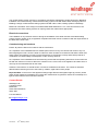
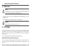
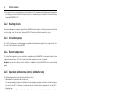
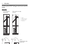
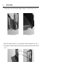
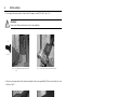
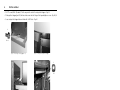
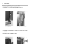
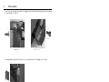
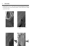
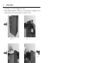
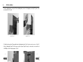
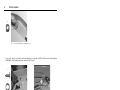
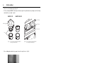
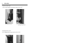
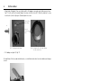
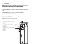
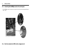
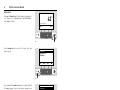
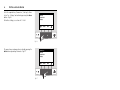
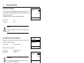
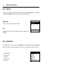
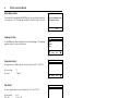
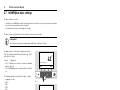
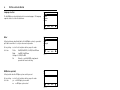
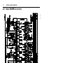
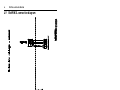
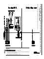
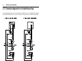
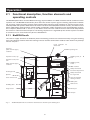
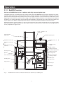
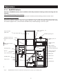
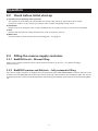
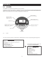
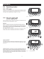
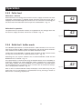
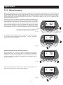
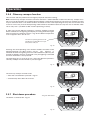
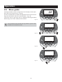
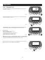
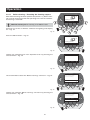
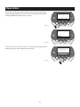
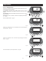
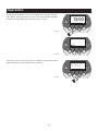
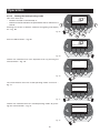
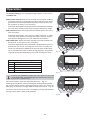
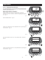
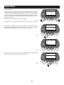
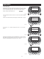
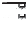
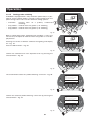
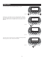
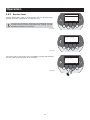
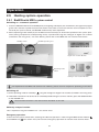
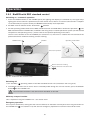
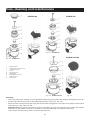
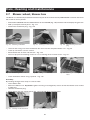
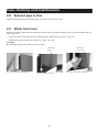
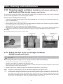
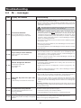
Care, cleaning and maintenance
BioWIN 100
BioWIN 150
Fig. 122
Fig. 120
1
2
3
4
5
6
7
8
BioWIN 100
BioWIN 150
Fig. 123
BioWIN 210/260
Fig. 121
Removal tool
Guide groove for the lock
in the burner pot
Cone
Primary air pin
Grate plate
Secondary air holes
Lock for cone
Burner pot
Fig. 124
BioWIN 210/260
Fig. 125
Assembly:
– Insert the grate plate, making sure the projection/opening of the grate plate projects through the driver of
the driving rod and rests fully on the bottom grate plate – Figs. 121, 123, 125.
– Place the cone into the burner pot using the removal tool. The groove in the cone must project into the lock
of the burner – Figs. 120, 122, 124.
Important: Before inserting the primary air pin, once again vacuum out the primary air tube in the middle
of the burner pot. Make sure there is no debris in the tube (damage to the ignition element!).
– Insert the primary air pin (on lock = note anti-twist device!).
41