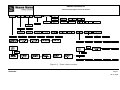
1
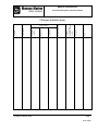
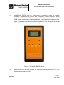
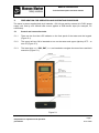
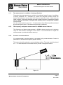
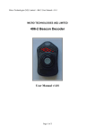
BEACON TESTER 406 02
Technical description and user manual
COSPAS-SARSAT Emergency
Position Indication Radio Beacon Tester
BEACON TESTER 406 02
Technical description and user manual
BEACON TESTER 406 02
Technical description and user manual
Changes indication page
Date
Signature
Internal
accompanying
document reference
number
canceled
New one
Changed or
updated
Item number
Changes
Page number
Document number
Changes indication page
Page 1
05.01.2008
BEACON TESTER 406 02
Technical description and user manual
Actual content pages
Item
Page
Date
05.01.08
Changes
indication page
1
Actual content
pages
1
Contents
1
05.01.08
Item 1
Purpose
1
2
05.01.08
05.01.08
Item 2
Main features and
characteristics
1
2
05.01.08
05.01.08
05.01.08
Item 3
Complete set
1
05.01.08
Item 4
Operation
1
05.01.08
1
2
3
4
5
6
7
8
9
10
11
12
05.01.08
05.01.08
05.01.08
05.01.08
05.01.08
05.01.08
05.01.08
05.01.08
05.01.08
05.01.08
05.01.08
05.01.08
Item 5
Preparation for
operation and
operation
procedures
Actual content pages
Item
Page
Date
Item 6
Measurement of
beacon’s
parameters
1
2
3
4
05.01.08
05.01.08
05.01.08
05.01.08
Item 7
Tester’s
calibration
1
05.01.08
Item 8
1
05.01.08
Item 9
1
05.01.08
Appendix
1
05.01.08
Page 1
05.01.2008
BEACON TESTER 406 02
Technical description and user manual
Contents
Item name
Item
Page
Changes indication page
1
Actual content pages
1
Contents
1
Purpose
1
1-2
Main features and characteristics
2
1-2
Complete set
3
1
Operation
4
1
Preparation for operation and operation procedures
5
1-12
Measurement of beacon’s parameters
6
1-4
Tester’s calibration
7
1
Maintenance
8
1
Storage rules
9
1
Appendix:
Appendix 1. Tester’s menu structure
Contents
1
Стр. 1
05.01.2008
BEACON TESTER 406 02
Technical description and user manual
1. PURPOSE
1.1
The BEACON TESTER 406 02 ( further tester) is intended to check the maritime
emergency radiobeacons of EPIRB type (Emergency Position Indicating Radio
Beacon) of COSPAS-SARSAT satellite system, either during efficient check (after
EPIRB coding or after being installed/reinstalled), or during annual acceptance tests.
The tester is capable to receive the EPIRB emission in test mode or real emergency
signals by means of both internal antenna and special RF cable connecting the EPIRB
and tester. The main view of tester is shown on figure 1-1.
Figure 1-1. BEACON TESTER 406 02
1.2
Item 1.
Also the tester can be used to check the emergency locating transmitters (ELT) or
personal locating beacons (PLB).
Page 1
Purpose
05.01.2008
BEACON TESTER 406 02
Technical description and user manual
1.3
The tester allows to perform the:
-
Reception and decoding of emergency signal in 406MHz channel
Measurement of 406MHz carrier frequency;
Control of sweep-tone of 121.5MHz carrier frequency;
Measurement of power level of received signal in 406MHz channel;
Measurement of power level of received signal in 121,5MHz channel;
Estimation of meaning of positive and negative phase of modulated signal;
Estimation of signal duration in 406MHz channel;
Estimation of non-modulated preamble duration in in 406MHz channel;
Calculation of equivalent emitted power based on measured signal level by means
of known calibration factor of internal antenna.
1.4
The tester is designed to operate in range of + 5оС до + 45оС external environments
and 95% relative humidity which is connected with LCD display implementation.
1.5
The tester is power supplied both by 4 batteries 1.5V AA type and by external 4.87VDC power supply unit, and by min 300mA load current applied to USB device input
(for example, PC connection).
Attention!!!
While using exterior power supply unit be careful to pay attention to its right
polarity.
The power supply units of different manufacturers have opposite polarity of
external signal! The polarity of power supply unit should be the same as shown
below or indicated on the bottom of tester’s case!
Item 1.
Page 2
Purpose
05.01.2008
BEACON TESTER 406 02
Technical description and user manual
2. Main features and characteristics.
2.1
Tester provides the measurement of carrier frequency in 406MHz channel with
accuracy ± 500 Hz.
Attention!!!
The tester’s operating range is extended upto 406018 … 406048 kHz and is devided on six
subranges (see Item 5.3.4). After the tester is powered ON the 406023 … 406028
kHz subrange is automatically tuned on The operating frequency of tested EPIRB
should be within the operating frequency range of tester.
2.2
The tester provides the check of the 121500±10 kHz carrier frequency and sweep-tone
presence by audio signal.
2.3
The tester provides the reception and complete decoding of the received emergency
message for all types of the protocols appropriate to the Recommendations C/S T-001,
allows to display the information as in hex-codes (separately 1-112 bits, 26-108 bits,
26-85 bits, 113-144 bits) as in text format with indicating of basic message’s
parameters. Besides, device makes the calculation of the ВСН code remainder and
compares it with received.
2.4
The tester makes measurement of a positive and negative phase deviation of the
modulated signal accurate within ± 2,8о.
2.5
The tester provides the check of the common time of transmission of the message
accurate within ±2 % and time of preamble duration accurate within +- 2%.
2.6
The tester provides measurement of received signal level in range of 19 – 40 dBm or
0.08 – 10 W in 406 Mhz channel with accuracy +1/-5 dB.
2.7
The tester provides measurement of received signal level in range of 13 – 20 dBm or
20 -100 mW with accuracy ± 3 dB.
2.8
The tester provides to carry out the beacon’s tests both by means of internal antenna
at 1…3 meters distance (recommended distance is 1 - 2 meters) and by means of RF
cable connecting the EPIRB and tester.
2.9
The resistance of internal attenuator (FR input) is (50 ± 1,5) Ohms.
ATTENTION !!!
The maximum level of signal applied to RF input continuously should not be
more then 7.0V or 1.0W.
2.10
The tester allows to save in non-volatile memory 10 blocks of the measured
parameters.
Item 2.
Page 1
Main features and characteristics
05.01.2008
BEACON TESTER 406 02
Technical description and user manual
2.11
Time of one measurement cycle is no more than 2 minutes.
The tester is power supplied both by 4 batteries 1.5V AA type and by external 4.8-7VDC power
supply unit, and by min 300mA load current applied to USB device input (for example, PC
connection).
2.12
Consumption currents :
in stand-by mode without LCD highlight - not more then 80 mA;
in stand-by mode with LCD highlight - not more then 120 mA;
in measurement mode with LCD highlight - not more then 200 mA.
2.13
The approximate time of continuous operation of tester supplied by internal batteries is
not less then 6 hours.
2.14
The tester is automatically powered off after 15 second any key pressed.
2.15
The tester estimates the internal batteries voltage with accuracy ± 5%.
Item 2.
Page 2
Main features and characteristics
05.01.2008
BEACON TESTER 406 02
Technical description and user manual
3.
COMPLETE SET.
3.1.
The complete set of tester includes the items in accordance with table 3-1.
Table 3-1
#
1
2
3
4
5
6
7
Item name
BEACON Tester 406 02
Power supply unit (USB Adaptor)
RF Cable
PC Cable (USB)
Technical operation and user
manual
Package
Software and user manual
Qty
1
1
1
1
1
Notes.
Optional
Optional
1
1
Serial No:_______________________________________________________
Issue date_______________________________________________________
Quality acceptance date:____________________________________________
Item 3.
Page 1
Complete set
05.01.2008
BEACON TESTER 406 02
Technical description and user manual
4.
OPERATION.
4.1
The measurement of beacon’s parameters can be carried out both by means of internal
attenuator with 40dB damping and by means of internal antenna. RF cable is
connected to corresponding input located on the upper front panel of the tester. (see
figure 5-1).
4.2
The measurement can be carried out independently – in this case the tester is power
supplied by internal batteries or stationary – the tester is power supplied by external
power supply unit – 220VAC/6-9VDC.
4.3
The signal from tested beacon comes to duplexer through attenuator or internal
antenna where is divided by filter on two separate signals and applied to two different
406MHz and 121,5Mhz receivers. The 406MHz receiver is superheterodyne executing
double frequency conversion. The first heterodyne has fixed 400MHz frequency and
second has tuned frequency allows to adjust the receiver with the beacon operating in
wide frequency range: 406 018 – 406 040 kHz. Both heterodynes covered by phaselocked-loop frequency control circuits that use the stable frequency of the temperaturecompensated reference generator.
4.4
The 121.5MHz receiver is superheterodyne with only one frequency conversion and
heterodyne affiliated to phase-locked-loop frequency control circuit.
4.5
The measurement of all parameters is carried out by the central controller clocked by
high-stable reference generator. The central controller also processing indicator,
keypad, and audio system. Besides, the central controller turn on only that parts are
required at a moment. This function allows saving the current consumption and
sending all data to RS-232 interface.
4.6
The tester uses the reference-voltage source to increase the accuracy of
measurements.
Item 4.
Page. 1
Operation
05.01.2008
BEACON TESTER 406 02
Technical description and user manual
5.
PREPARATION FOR OPERATION AND OPERATING PROCEDURE.
The tester is power supplied both by 4 batteries 1.5V AA type and by external 4.8-7VDC power
supply unit, and by min 300mA load current applied to USB device input (for example, PC
connection).
5.1
Control and connection tools.
5.1.1
There are the four-line LCD indicator on the front panel of the tester and the keypad.
(Figure 5-1).
5.1.2
The upper left key ON is intended to turn on the tester and upper right key OFF – to
turn off. (Figure 5-1).
5.1.3
The lower keys «<», ESC, ENT, «>» are intended to navigate the menu items and their
execution (Figure 5-1).
Figure 5-1
Item 5.
Preparation for operation and operation
procedures
Page 1
05.01.2008
BEACON TESTER 406 02
Technical description and user manual
5.1.4
The RF input is located on the upper panel of the tester. The PC and power supply
outputs are located on the bottom panel. (Figure 5-1).
5.2
Power on and off the tester
5.2.1
The tester can be turned on by pressing the ON key and holding until the message with
battery voltage and inside temperature is displayed on LCD:
WELCOM!
BST XXXX
U= XX,XXV
ALEXS V 1.3
Also there is an audio signal. Then please release the ON key. If you will continue to
hold the key for 5 seconds the tester will be turned off. The battery voltage is displayed
on LCD. The normal voltage is that more then 5.2V.
5.2.2
The tester is turned off in following cases:
-
5.3
Press and release the OFF key;
Hold the ON key for 10 seconds and then release it.
No keys are pressed for 15 minutes.
Tester’s navigation menu.
After turning on tester displays the battery voltage and inside temperature, you will see
the message:
MEASURE>
The tester’s menu has a structure presented in appendix. The horizontal movements
are carried out by means of «<» and «>» keys (in accordance with LCD icons «<» and
«>».
The vertical movements are carried out by means of ENT key – downwards or
execution and ESC key – up or exit menu item.
The main (upper) menu contents six main items:
MEASURE>
<VIEW>
<PC LINKS>
<CONTROL>
- measure the beacon’s parameters;
- view the test results;
- connection and saving the test results to PC;
- selection of frequency subrange in 406MHz channel;
Item 5.
Preparation for operation and operation
procedures
Page 2
05.01.2008
BEACON TESTER 406 02
Technical description and user manual
<SETUP>
- parameters setup, saving of the data in non-volatile memory and
charge of a storage battery;
<TEST
- test option of the tester’s parameters.
Each item of the main menu has subitems, you can navigate the submenu by means of
the same keys.
Press the ESC key to return to main menu.
5.3.1
MEASURE> - MEASUREMENTS
After tester is turned on you see the following menu item:
MEASURE>
"MEASUREMENTS"
By pressing the ENT key the tester will be switched to AUTO> subitem – automatic
measurement mode, check of all parameters.
By pressing the «>» key the tester will be switched to manual mode to make you
capable to check some parameter separately.
<AUDIOTES>
<T SEQ>
<LEV. 406>
<LEV. 121>
<RESERV
- audio control of sweep-tone presence;
- measurement of total message duration in 406MHz channel;
- measurement of received signal level in 406MHz channel;
- measurement of received signal level in 121.5MHz channel;
- reserve subitem, it’s not recommended to use it.
5.3.1.1 AUTO> subitem – automatic measurement mode.
All beacon’s parameters can be measured in AUTO> mode.
-
Measurement of the 406 MHz frequency carrier;
Check the presence of the 121,5 MHz frequency and the sweep-tone.
Measurement of the values of the positive and negative phase;
Measurement of the total message duration in 406 MHz channel;
Measurement of the non-modulated preamble duration i.e. period from the
beginning of the 406 MHz carrier’s transmission to the beginning of the phase
modulation;
Measurement of the signal’s level in 406 MHz channel;
Measurement of the signal’s level in 121.5 MHz channel;
information rate in 406 MHz channel;
Complete decoding of received message.
After pressing the ENT button in submenu AUTO > the display shows the message:
Item 5.
Preparation for operation and operation
procedures
Page 3
05.01.2008
BEACON TESTER 406 02
Technical description and user manual
ON BEACON
AND GO ON
"TURN ON THE BEACON AND STAND AWAY"
Then press the ENT key to start the measurements. The LCD display shows:
MEASURING!
WAIT!
The measurements are accompanied by audio indication of the sweep-tone signal. All
cycle of measurements is not longer than 2 minutes. Then the tester displays:
OFF BEACON
ACCOUNT
In case if you choose the wrong frequency range the tester displays the message:
CAPTURE ERROR
After the tester made all measurements it displays the message:
VIEW
AUTO
NEXT?
"VIEW"
"AUTOMATIC MODE"
"NEXT PARAMETER?"
The measured parameters can be sequentially viewed, without using the VIEW mode –
by pressing any of the «<», ENT, «>» keys.
The measured parameters are displayed in following order:
-
the meaning of 406MHz carrier frequency - in Hz;
the meaning of positive and negative phase – in degrees;
the meaning of modulated signal’s slope and rise duration - in microseconds;
the meaning of message duration – in milliseconds;
the level of received signal in 406MHz channel – in dBm;
the level of received signal in 121.5MHz channel – in dBm;
decoded message;
information rate – in bauds.
The received message can be viewed in several modes.
Item 5.
Preparation for operation and operation
procedures
Page 4
05.01.2008
BEACON TESTER 406 02
Technical description and user manual
Navigate the "SEQUENCE" subitem by means of «<», «>» key and execute your
choice by pressing ENT key to see the message in НЕХ–format: 1 … 112 bits <1-112>,
25…108 bits - <25-108>, 26…85 bits (15 HEX ID) - <26 - 85> and 113…144 bits
<113-144> (if the message is long).
While entering the menu ВСН> ВСН (Bose-Chaudhuri-Hocquenghem code) remainder
is calculated according to the received bits and then is compared with received
remainder bit-by-bit. In case of complete concurrence the next message appears on
the display:
ВСН О'К
Otherwise:
BCH BAD
This test allows estimating if the ВСН code calculations are correct in the message and
confirms the absence of errors.
If the ESC button is pressed in submenu SEQUENCE the display shows the message:
VIEW
AUTO
NEXT?
by pressing ENT, the fragments of the received message are displayed in ASCII format
(as text).
В подпункте МAIN> "ОСНОВНОЕ" - выводится код страны и номер АРБ или
координаты и принадлежность к определенному типу.
In МAIN> subitem LCD displays the country code, beacon’s number or coordinates,
beacon’s type.
In <EXT.1> subitem LCD displays the presence of home transmitter, its type, beacon
activation type.
The tester decodes the beacons of any type or subtype in accordance to COSPAS SARSAT C/S T.001 requirements.
The <EXT 2> is intetned for further tester’s improvements or modifications.
Press ESC key to return to main menu.
The measured and calculated parameters at that are saved until next measurement or
power off the tester. But after that the parameters can be viewed only by means of
VIEW main menu item.
Item 5.
Preparation for operation and operation
procedures
Page 5
05.01.2008
BEACON TESTER 406 02
Technical description and user manual
5.3.1.2 <AUDIOTES> subitem – audio control of sweep-tone presence.
This subitem is indented to check the presence of sweep-tone of home 121.5MHz
transmitter.
The following message is displayed after pressing the ENT key:
MEASURE>
<AUDIOTES>
IN WORK!
5.3.1.3 <T SEQ> subitem – measurement of message duration.
The following message is displayed after pressing the ENT key in <T SEQ> subitem:
MEASURING!
WAIT!
And then the results in milliseconds are displayed.
The results are saved until the tester is powered on and can be viewed by means of
VIEW main menu item.
5.3.1.4 <LEV.406> subitem – measurement of received signal level in 406 MHz channel.
The following message is displayed after pressing the ENT key in <LEV.406> subitem:
MEASURING!
WAIT!
And then the results in dBm are displayed.
The results are saved until the tester is powered on and can be viewed by means of
VIEW main menu item.
5.3.1.5 <LEV.121> subitem – measurement of received signal level in 121.5MHz channel.
The following message is displayed after pressing the ENT key in <LEV.121> subitem:
MEASURING!
WAIT!
accompanied with audio signal of sweep-tone presence and then the results in dBm
are displayed.
Item 5.
Preparation for operation and operation
procedures
Page 6
05.01.2008
BEACON TESTER 406 02
Technical description and user manual
The results are saved until the tester is powered on and can be viewed by means of
VIEW main menu item.
5.3.1.6 <REZERV subitem – reserve item.
The subitem is reserve and it is not recommended to press the ENT key in this item. To
escape this item is possible only after powering off the tester.
5.3.2.
<VIEW> subitem – the viewing of measurement results.
This item is intended to view the test results and has two subitems:
AUTO>
- the viewing of the measurement results carried out in automatic mode;
<DUMP>
- the viewing of controller memory contents.
The measurement results can be viewed immediately after measurements or after
loading from nonvolatile memory. 10 blocks of measurements maximum can be saved
in the memory.
5.3.2.1 AUTO> subitem of <VIEW> item.
By means of this item all results measured in AUTO>, <MANUAL> modes or loaded
from memory can be viewed.
Use the «<» и «>», key to choose the parameter you would like to see and execute its
viewing by ENT key. As opposed to viewing in MEASURE>, AUTO> mode – the
following parameters can be viewed in <VIEW> mode:
406MHz>
<PHASE>
<T PHASE>
just estimation;
<Т SEQ.>
<Т PRE.>
<LEV.406 >
<LEV. 121>
<SEQ.HEX>
<SEQ.ASCI>
<BAUDRATE
- the meaning of measured frequency in 406MHz channel;
- the meaning of positive and negative phase;
- the meaning of phase slope and rise duration. This parameter is
- the total duration of data message;
- the duration of non-modulated preamble;
- the level of received signal in 406MHz channel;
- the level of received signal in 121.5MHz channel;
- contents of received message in HEX – format;
- decoded message in text format;
- data rate.
The data loaded from memory can also be viewed by means of «<», «>» и ENT keys.
5.3.2.2. <DUMP subitem of <VIEW> item.
This item is intended to view the memory contents of controller and has only
technological feature.
Item 5.
Preparation for operation and operation
procedures
Page 7
05.01.2008
BEACON TESTER 406 02
Technical description and user manual
5.3.3
<PC LINKS> item - connection and data transmitting to personal computer (PC).
This item is intended to transmit the measurement results to personal computer. The
suitable software should be installed in PC. The data transmitting begins after pressing
the ENT key. After the LCD displays SAVE? It is necessary to press the ENT key
again. Do not forget to connect the tester to PC by means of the PC cable.
5.3.4 <CONTROL> item – select the subrange of 406MHz frequency.
This item is intended for selection one of following subranges:
- 018 - 023: 0 - 406,018 ... 406,023 MHz subrange;
- 023 - 028: 1 - 406,023 ... 406,028 MHz subrange (default);
- 028 - 033: 2 - 406,028 ... 406,033 MHz subrange;
- 033 - 038: 3 - 406,033 ... 406,038 MHz subrange;
- 038 - 043: 4 - 406,038 ... 406,043 MHz subrange;
- 043 - 048: 5 - 406,043 ... 406,048 MHz subrange.
The selected subrange is not saved after power is off.
5.3.5
<SETUP> item - setup the tester’s parameters.
This item is intended to allow saving or loading the measurement results from or to
nonvolatile memory. Also some parameters of the tester can be setup. <SETUP> item
has seven subitems:
SAVE>
- saving the measurement results of beacon in nonvolatile
memory;
<LOAD>
- loading the results that were saved in memory to be capable to
view them in <VIEW> mode;
<CURRENT>
- restore the current measurement results;
<DATE>
- measurement date setup;
<N MEAS.>
- number of measurement that was carried out by tester;
<BLC.OFF>
- LCD backlight on or off setup;
<NAME
- Family name of responsible person, will be printed in
measurement protocol;
5.3.5.1 SAVE> subitem – saving the measurement results.
The tester has the non-volatile memory keeps the saving data when the tester is
powered off. The size of this memory allows storing of 10 measurement results. The
blocks contain all parameters measured in the AUTO > mode, also all parameters,
measured in manual mode and saved in the memory.
Each block saved in the memory has the number from "0" up to "9". It is possible to
load the exact block from the memory by the <LOAD> submenu selecting by block
number, by the date of saving or by current number of measurement To save the
measurement automatically it is necessary to make measurement in AUTO > mode.
Item 5.
Preparation for operation and operation
procedures
Page 8
05.01.2008
BEACON TESTER 406 02
Technical description and user manual
Press ENT in submenu <SAVE > to save the block of the measurement results. The
display shows the message in a bottom line:
BEACON X
Х - Number of the block from "0" up to "9".
The number of blocks is given automatically, from "0" and up to "9", then again "0" etc.
Thus, memory contains 10 last blocks.
When pressing ENT key the memory saves the block. When pressing the button ESC
the memory doesn’t save the block. It is impossible to save tow times the same block.
5.3.5.2 <LOAD> item – loading of measurement results saved in nonvolatile memory.
Any block saved in the memory can be viewed by <VIEW> menu.
After pressing the button ENT in the <LOAD> item the display shows the message:
LOAD?
NМ=ХХХХХ
ХХ.ХХ.20ХХ
BEACON X
The display shows the number of the block in the bottom line which can be viewed now
by <VIEW>. The data of the measurements is shown too.
It is recommended to set the date after the tester is powered on, as the it has no
internal hours or calendar.
The five-digit number of measurements is shown in the second line of the display.
Each measurement in <AUTO> mode increases this number by one, which gives the
information about the total number of measurements, made by the tester, and helps to
identify the block.
Press the ENT key to load this block for viewing by <VIEW>.
It is possible to load for viewing any of 10 blocks by pressing the ← and → keys.
Press the ESC button to cancel the viewing.
5.3.5.3 <CURRENT> subitem – restore for viewing the current (last) measurement
results.
When entering the <VIEW> item - viewer of the block of parameters from non-volatile
memory, the available in <VIEW> data are reloaded to the temporary buffer and can
be restored by pressing of the ENT button in the <CURRENT> submenu.
This submenu can be used, when it is necessary to compare the obtained data
with the data saved earlier in non-volatile memory after the measurements. The
Item 5.
Preparation for operation and operation
procedures
Page 9
05.01.2008
BEACON TESTER 406 02
Technical description and user manual
necessary block is load in <VIEW> by the <LOAD> and then by the <CURRENT>.
5.3.5.4
<DATE> subitem – current date.
The tester has not internal hours or calendar and consequently it is necessary to set
the current date manually. The date is printed in the test protocol, and also helps to
identify the data blocks saved in non-volatile memory.
<DATE> has two subitems:
ENT.DATE>
- setup the date;
<CLR DATE
- clearing the date.
Set the necessary date by the button <- , -> and ENT in menu DATE>:
Number
Month
Year
Press the ESC key to leave the menu.
Press the ENT key in <CLRDATE> subitem to clear the date.
In this case, the spaces will be printed instead of the exact date.
5.3.5.5 <N MEAS.> subitem - viewing of number of last measurement.
Each measurement in AUTO> mode increases the number of measurement by one.
Current five-digit number of measurements is displayed in blocks of the measurements
which have been saved in non-volatile memory.
Press the button ENT to view the current number of measurements. It is impossible to
change this number.
5.3.5.6 <BLC.OFF> subitem – set the backlight.
Press the ENT key to change the mode of the backlight from ON to OFF.
ON - the backlight is turned on during operation of the tester.
OFF- the backlight is turned off during operation of the tester.
5.3.5.7 <NAME – Save the family name of responsible person.
5.3.6
<TEST Item – testing of the tester’s parameters.
This item is intended for obtaining of the special and technological information and
consists of 4 subitems:
UCC>
<TEMPERAT>
<POW. TEST>
<POW. SUP
- indication of the batteries voltage;
- indication of temperature inside the tester;
- power measurement in continuous mode;
- technological item.
Item 5.
Preparation for operation and operation
procedures
Page 10
05.01.2008
BEACON TESTER 406 02
Technical description and user manual
The UCC > and < TEMPERAT > can be only usefully used.
Other subitems are intended for technological testing of the tester and detailed
research of beacon’s operation laboratories. Therefore only two subitems are
described below:
5.3.6.1 UCC> - indication of batteries voltage.
Press the ENT key to display the voltage of the batteries. The minimum opreation
voltage is Ucc= 5.2V.
5.3.5.2 <TEMPERAT> item – inside temperature of the tester.
Press the ENT key in <TEMPERAT> subitem to display the temperature inside of the
tester in C degrees.
It is necessary to know this parameter in hot conditions of operation.
The value of the temperature should not exceed 50°C and should not be lower than
15°C degrees.
5.4. Operation supplied by external power supply unit
The USB adaptor, included optionally, can be used as external power supply from
220VAC. Also the tester can be supplied by USB connection with PC.
Attention: All drivers to connect the tester to PC etc can be found at our website:
www.gmdsstesters.com in Download section.
Item 5.
Preparation for operation and operation
procedures
Page 11
05.01.2008
BEACON TESTER 406 02
Technical description and user manual
6.
Measurement of beacon’s parameters
6.1
Common remarks concerning the measurement of beacon’s parameters
Attention !!!
During beacon’s tests and maintenance the special attention should be paid to
avoid the false transmission of emergency signals.
Use the special shielded room or box during the measurement by means of
antenna throughout the broadcast. The shielded room or box should provide the
RF signal attenuation not less then 80dB. (Under COSPAS-SARSAT
recommendations).
6.2
Measurements.
6.2.1
Prepare the beacon and tester for measurements in accordance with requirements of
this user manual and beacon’s operation and user manual.
6.2.2
Connect the RF–cable to RF input of the tester and antenna output of beacon in case if
measurements are carried out by means of RF-cable. (see Figure 5-1).
6.2.3
Power on the tester in accordance with item 5 of this manual.
6.2.4
Power on the beacon in accordance with its operation manual.
6.2.5
Measure all parameters of emitted signal in accordance with item 5 of this manual.
6.2.6
Use the personal computer (PC) to document the measurement results. Connect the
tester to PC by means of PC cable and use the software.
6.3
Measurements by means of antenna.
6.3.1
The estimation of equivalent emitted power (EEP).
EEP is multiplication of power supplie to antenna and the multiplication factor of
antenna. Thus it depends on measurement environments and position chosen for
metering of field density. The meaning of EEP is only estimation as we can not
completely take into account all reflection of RF-signal from surrounding objects.
Besides the EEP tolerance is as follows below in accordance with COPSAS-SARSAT
C/S T.001 taking into account the power tolerance of transmitter ±2 dB and
multiplication factor of antenna = (+4/-3) dB:
EEPmin = 37-2 - 3 = 32 dBm or 1,6 W
EEPmax = 37+2+4 = 43 dBm or 20 W ,
This is actual for 90% area limited by 5° and 60° elevations, in other cases the EEP can
be less.
Item 6.
Page 1
Measurements of beacon’s parameters
05.01.2008
BEACON TESTER 406 02
Technical description and user manual
6.3.2
The measurement in condition of strong reflections.
Frequently the measurements are carried out in straitened vessel’s rooms in conditions
of strong reflections. It is necessary to provide the subjacent surface around the
beacon with diameter not less then 1.25 meter at water-line level. In this case two
types of signal – direct and reflected will come to tester’s antenna. Otherwise the signal
level is collapsed that leads to reception and decoding errors, wrong phase deviation
measurements.
So it is recommended to carry out 3…5 measurements from different positions selected
by received signal’s level. The maximum signal level is preferred.
6.3.3
The frequency and phase measurements in 406MHz channel features.
The frequency and phase measurements in 406MHz channel can be out of tolerance
range for first beacon’s messages in test mode. It is recommended to repeat the
measurements to provide the beacon warm up.
6.3.4
Common recommendations.
It is recommended to set the beacon in test mode during measurements of beacon’s
parameters to avoid false emergency signals emitting.
The beacon should be placed on some underlying surface. The tester should be placed
at 1…1.5 meters distance in horizontal area to provide 10 degrees elevation.
Figure 6-1
Item 6.
Page 2
Measurements of beacon’s parameters
05.01.2008
BEACON TESTER 406 02
Technical description and user manual
7.
Tester’s calibration.
The tester is a complex special-use electric device. Thus it is should be calibrated only
by manufacturer by means of corresponding equipment.
The tester should be calibrated every two years or after 1000 measurements are
carried out.
The tester is automatically powered off when 1000 measurements were carried out. It
can not be powered on after that.
The further usage of tester is possible only after its calibration by manufacturer or by
laboratories certified by manufacturer.
Date of next calibration:_____________________________________
Item 7.
Page 1
Tester’s calibration
05.01.2008
BEACON TESTER 406 02
Technical description and user manual
8.
Maintenance.
It is necessary to keep the device in package not less then for two hours at normal
conditions when it was at high temperature deviation.
Keep it the package in at normal condition within 12 hours after storage of the tester in
conditions of high humidity.
Item 8.
Page. 1
Maintenance
05.01.2008
BEACON TESTER 406 02
Technical description and user manual
9.
Storage rules.
The device should be stored in package in warehouse locations defending it from
effect of atmospheric precipitation.
Temperature in warehouse should be ensured from 278 K (5 С) up to 313K (40 about
С) and relative humidity of air no more than 80%.
Item 9.
Page 1
Storage rules
05.01.2008
BEACON TESTER 406 02
Technical description and user manual
Figure A -1. Tester’s menu structure
APPENDIX
Page 1
05.01.2008