1
OPTOSENSE LLC
Design Department
USER MANUAL
SMALL-SIZE EXPLOSIVE GAS MEASURING SENSOR MIPEX-02-Х-X-X.1 X
SMALL-SIZE EXPLOSIVE GAS MEASURING
SENSOR MIPEX-02-Х-X-X.1 X
USER MANUAL
ESAT.413347.005 UM
File name: ESAT.413347.006 UM v.2.0.docx
Revision 2.0 27 August 2015
Page. 1 of 38
THE SOLE PROPERTY OF OPTOSENSE LLC. ANY REPRODUCTION WITHOUT THE WRITTEN PERMISSION OF OPTOSENSE LLC IS PROHIBITED.
OPTOSENSE LLC
Design Department
USER MANUAL
SMALL-SIZE EXPLOSIVE GAS MEASURING SENSOR MIPEX-02-Х-X-X.1 X
THE INFORMATION CONTAINED IN THIS DOCUMENT IS THE SOLE PROPERTY OF
OPTOSENSE LLC. ANY REPRODUCTION IN PART OR AS A WHOLE WITHOUT THE
WRITTEN PERMISSION OF OPTOSENSE LLC IS PROHIBITED.
Document revisions
Rev.
Date
Common changes
1.34
16 July 2014
Released version
2.0
27 August 2015
Formatting.
Typical sensor sensitivity for different hydrocarbons.
Description of RX code.
Dust filter specification.
File name: ESAT.413347.006 UM v.2.0.docx
Revision 2.0 27 August 2015
Page. 2 of 38
THE SOLE PROPERTY OF OPTOSENSE LLC. ANY REPRODUCTION WITHOUT THE WRITTEN PERMISSION OF OPTOSENSE LLC IS PROHIBITED.
OPTOSENSE LLC
Design Department
USER MANUAL
SMALL-SIZE EXPLOSIVE GAS MEASURING SENSOR MIPEX-02-Х-X-X.1 X
Table of Contents
INTRODUCTION ............................................................................................................................ 4
1.
DESCRIPTION........................................................................................................................ 5
2.
TECHNICAL SPECIFICATIONS ............................................................................................. 6
3.
INTRINSIC SAFETY ............................................................................................................... 8
4.
PRECAUTIONS ...................................................................................................................... 9
5.
INSTALLATION AND SERVICES ........................................................................................ 10
6.
STORAGE AND TRANSPORTATION .................................................................................. 12
7.
WARRANTY ......................................................................................................................... 13
8.
CONTACTS .......................................................................................................................... 14
APPENDIX A.
SENSOR TYPES AND CHARACTERISTICS. ............................................... 15
APPENDIX B.
CONNECTION DIAGRAM. ............................................................................ 21
APPENDIX C.
UART COMMUNICATION PROTOCOL. ....................................................... 24
C.1. General information ........................................................................................................... 24
C.2. Work modes ...................................................................................................................... 24
C.3. Protocol commands........................................................................................................... 24
C.3.1.
Operating commands ........................................................................................ 24
C.3.2.
Request commands of factory settings and properties....................................... 28
C.3.3.
Sensor setting and calibration commands ......................................................... 30
C.4. Firmware update ............................................................................................................... 32
C.5. Troubleshooting ................................................................................................................ 33
APPENDIX D.
SENSOR ZEROING AND CALIBRATION. .................................................... 34
D.1. Zeroing .............................................................................................................................. 34
D.1.1.
Autozero. ........................................................................................................... 34
D.1.2.
Manual zeroing in whole temperature range. ..................................................... 35
D.1.3.
Manual zeroing in different points of temperature range. ................................... 35
D.2. Scaling .............................................................................................................................. 35
APPENDIX E.
DUST FILTERS. ................................................................................................ 38
List of abbreviations:
CGM – Control Gas Mixture;
EMI - Electromagnetic Interference;
LEL – Lower Explosive Limit;
NDIR - Non-Dispersive Infra-Red;
UART - Universal Asynchronous Receiver/Transmitter.
File name: ESAT.413347.006 UM v.2.0.docx
Revision 2.0 27 August 2015
Page. 3 of 38
THE SOLE PROPERTY OF OPTOSENSE LLC. ANY REPRODUCTION WITHOUT THE WRITTEN PERMISSION OF OPTOSENSE LLC IS PROHIBITED.
OPTOSENSE LLC
Design Department
USER MANUAL
SMALL-SIZE EXPLOSIVE GAS MEASURING SENSOR MIPEX-02-Х-X-X.1 X
INTRODUCTION
MIPEX-02-Х-Х-X.1 X (hereinafter, sensor or MIPEX-02) is the gas sensor, which is intended
for automatic continuous measurement of concentration of hydrocarbons in explosive areas and
carbon dioxide. The sensor is used for gas detection in atmosphere.
Sensor can be used as part of gas-analyzing equipment of groups I and II according to IEC
60079-0 in the explosion-hazardous zones of classes 0, 1, 2 according to IEC 60079-10-1, and
Class I, Division 1 according to UL Std. 913, CAN/CSA Std. C22.2 No.157-92.
Optosense LLC reserves the right to update and change current user manual in parts
excluding intrinsic safety parameters and accompanied information specified below.
File name: ESAT.413347.006 UM v.2.0.docx
Revision 2.0 27 August 2015
Page. 4 of 38
THE SOLE PROPERTY OF OPTOSENSE LLC. ANY REPRODUCTION WITHOUT THE WRITTEN PERMISSION OF OPTOSENSE LLC IS PROHIBITED.
OPTOSENSE LLC
Design Department
USER MANUAL
SMALL-SIZE EXPLOSIVE GAS MEASURING SENSOR MIPEX-02-Х-X-X.1 X
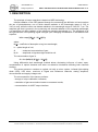
1. DESCRIPTION
The principle of sensor operation is based on NDIR technology.
Infrared radiation of the LED passed through the measuring gas diffusion cell and reaches
the two of photodetectors, one of which detects radiation in the wavelength range of 3.25 to
3.45 m only, while the other one detects radiation in the wavelength range of 3.45 to 3.7 m. The
analyzed gas that is present in the measuring cell absorbs radiation of the operating wavelength
(o) and does not affect radiation of the reference operating wavelength (r). The amplitude Io of
the light-sensitive cell operating signal changes upon changing concentration in accordance with
equation:
Io/Ir = ехр {-[К(o) – К (r)]СL};
(1)
where:
К () – coefficient of absorption at a given wavelength;
L – optical length of cell;
С
– measured concentration of gas;
Io, Ir
– amplitude of signals at light-sensitive cell.
The concentration of gas is:
С = -Ln (Io/Ir)/(L [K (o) – К (r)]);
(2)
Using differential dual wavelength method allows eliminating influence of water vapor,
contamination of optical elements and other non-selective hindrances affecting both channels
similarly.
The sensor structure contains an optical cell with a mirror system, infrared light-emitting
diode (LED), LED driver, receivers of Signal and Reference channels, analog amplifiers,
microcontroller and supply voltages unit.
The microcontroller of the sensor performs:
- storage of unique calibration constants;
- calculation of gas concentration based on measured results;
- communication via UART output interface.
File name: ESAT.413347.006 UM v.2.0.docx
Revision 2.0 27 August 2015
Page. 5 of 38
THE SOLE PROPERTY OF OPTOSENSE LLC. ANY REPRODUCTION WITHOUT THE WRITTEN PERMISSION OF OPTOSENSE LLC IS PROHIBITED.
OPTOSENSE LLC
USER MANUAL
Design Department
SMALL-SIZE EXPLOSIVE GAS MEASURING SENSOR MIPEX-02-Х-X-X.1 X
2. TECHNICAL SPECIFICATIONS
Table 1. Technical specification (available options see Appendix A).
Gas sampling method:
Diffusion
Operating principle:
Non-Dispersive Infra-Red (NDIR)
CH4
CH4 /CH4 +С2Н6
Target gas
C3H8
CO2
Operating,
storage and
transportation
conditions:
Relative humidity, %
up to 98
Atmospheric
pressure, kPa
80-120
Operating
temperature*, °C
-55... +60
General
-10… +40
Temperature range*, °C
-40… +60
-20… +50
Overall dimensions, mm
Pins length, mm
ø20х16.5 without pins (standard and plastic versions)
ø22х16.5 without pins (fast response versions)
4,6
5.75
16,6
Weight, g
15,5
5,5
Housing
MTBF, years
Ingress protection (IP) rating
Stainless steel (standard and fast response versions)
Plastic
10
20 (without dust filter)
54 (with dust filter)
0-1.5
Measurement
Measurement range, % Vol
0-2.5
0-5
0-100
Accuracy (UART data)
Up to 0.05% Vol or 5% of indication for CO2 and C3H8
Up to 0.1% Vol or 5% of indication for CH4
10
Response time (T90), s
20
30
60
File name: ESAT.413347.006 UM v.2.0.docx
Revision 2.0 27 August 2015
Page. 6 of 38
THE SOLE PROPERTY OF OPTOSENSE LLC. ANY REPRODUCTION WITHOUT THE WRITTEN PERMISSION OF OPTOSENSE LLC IS PROHIBITED.
OPTOSENSE LLC
Electrical
Design Department
USER MANUAL
SMALL-SIZE EXPLOSIVE GAS MEASURING SENSOR MIPEX-02-Х-X-X.1 X
Supply Voltage Range:
+3.0… +5.0 VDC
Output signal
digital UART
Power consumption, mW
<5
Warm-up time (not more), min
2
Degree of personal protection against
electrical shock caused by the sensor
meets the requirement of class III GOST 12.2.007.0
Ex ia I U/Ex ia IIC U. acc. to ГОСТ Р МЭК 60079-0,
ГОСТ Р МЭК 60079-11, ТР ТС 012/2011
Ex ia I Ma/Ex ia IIC Ga. acc. to IEC60079-0, IEC6007911, IEC60079-26. -55⁰ ≤ Ta ≤ +60 ⁰C
Marking and standards
compliance
IM 1/II 1 G Ex ia I Ma / Ex ia IIC Ga. acc. to EN60079-0,
EN60079-11, EN60079-26. -55⁰ ≤ Ta ≤ +60 ⁰C
* Term operation temperature means the ambient temperature where the sensor can be used
safely, but the sensor accuracy supported only in temperature range (see Table 3 and Table 5).
File name: ESAT.413347.006 UM v.2.0.docx
Revision 2.0 27 August 2015
Page. 7 of 38
THE SOLE PROPERTY OF OPTOSENSE LLC. ANY REPRODUCTION WITHOUT THE WRITTEN PERMISSION OF OPTOSENSE LLC IS PROHIBITED.
OPTOSENSE LLC
Design Department
USER MANUAL
SMALL-SIZE EXPLOSIVE GAS MEASURING SENSOR MIPEX-02-Х-X-X.1 X
3. INTRINSIC SAFETY
Combined intrinsically safe parameters of sensor circuits are as follows:
IECEx/ATEX: Ui = 5.0V, Ii = 450mA, Pi = 0.25W, Ci = 38.8µF, Li = 0 mH.
CAN/CSA: Vmax = 5.0V, Imax = 450mA, Pmax = 0.25W, Ci = 38.8µF, Li = 0 mH.
It is allowed to connect the sensor only to intrinsically safe circuits with the rated direct
current output voltage (U0) within the range of not less than 3 V and not more than 5 V, with the
output power (P0) - not less than 0.02 W and not more than 0.25 W.
The gas-analyzing equipment, which is used with MIPEX-02, must meet the requirements of
IEC60079–0, IEC60079–11, IEC 60079-14 and have parameters conforming the MIPEX-02
intrinsic safety pointed above.
File name: ESAT.413347.006 UM v.2.0.docx
Revision 2.0 27 August 2015
Page. 8 of 38
THE SOLE PROPERTY OF OPTOSENSE LLC. ANY REPRODUCTION WITHOUT THE WRITTEN PERMISSION OF OPTOSENSE LLC IS PROHIBITED.
OPTOSENSE LLC
Design Department
USER MANUAL
SMALL-SIZE EXPLOSIVE GAS MEASURING SENSOR MIPEX-02-Х-X-X.1 X
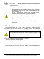
4. PRECAUTIONS
Inspection and maintenance of the sensor should be carried out by suitably trained
personnel in accordance with the applicable code of practice (e.g. EN 60079-17).
Any person who have studied this UM, have been briefed on safety precautions when
operating electrical equipment intended for operation in the explosion-hazardous zones in
the established order, is admitted to operate the sensor.
Do not use damaged sensor. Unauthorized repair of the sensor is not allowed.
It is strongly prohibited to discharge the control gas mixture (CGM) to the atmosphere
during the sensor calibration.
Do not allow the contact of the sensor with aggressive substances e.g. acidic liquids or
gases that might attack metals, or solvents that might affect polymeric materials.
The sensor does not contain any poisons and other harmful substances that might be
released from the sensor during its operation. Risk to humans and environment does not
exist.
File name: ESAT.413347.006 UM v.2.0.docx
Revision 2.0 27 August 2015
Page. 9 of 38
THE SOLE PROPERTY OF OPTOSENSE LLC. ANY REPRODUCTION WITHOUT THE WRITTEN PERMISSION OF OPTOSENSE LLC IS PROHIBITED.
OPTOSENSE LLC
Design Department
USER MANUAL
SMALL-SIZE EXPLOSIVE GAS MEASURING SENSOR MIPEX-02-Х-X-X.1 X
5. INSTALLATION AND SERVICES
5.1
Models MIPEX-02-X-X-3.1 X are potential electrostatic charging hazard –
clean them with a damp cloth only. Take it into account during installation
and operation of the sensor in end-user equipment.
The MIPEX-02-X-X-1.1 X and MIPEX-02-X-X-2.1 X models of the
equipment were tested and found to hold 17.4pF maximum capacitance.
Connection should be made via PCB sockets. Soldering to the pins will
seriously damage the sensor.
Excessive force on sensor housing is not allowed. For the metal housing no more than 2 MPa applied to reflecting cover center or on at any point of
middle part side surface and no more 100 MPa applied to boundary of
reflecting cover. For the plastic housing - no more than 20 kPa applied to
reflecting cover center or on at any point of side surface and no more 2
MPa applied to boundary of reflecting cover.
Metrological properties are not supported in ambient temperature gradient
faster than 0.6 ⁰C/min.
Set manual zeroing procedure after continues storage or transportation.
Preparation
5.1.1
If the sensor has been kept in the transportation package at temperature lower than
00C, hold it at temperature of 10–35 0C for at least one hour.
5.1.2
Remove the packing. Check presence of the certification marking, ensure absence
of mechanical injuries.
5.2
Installation
Use intrinsic safety connection (see Appendix B for details).
5.2.1
Use the following recommended sockets for the sensor connection or similar:
Cambion 450-3729-01-06-00;
Harwin H3183-05;
Harwin H3182 (for the MIPEX-02-X-X-X.1 A modification).
Sensor pinout is shown in Fig. 1 of Appendix A.
5.2.2
Provide intrinsically safe power supply to the sensor from power sources featuring
nominal range of output DC voltage of not less than 3 V and not more than 5 V,
output power (P0) – not less than 0.02 W and not more than 0.25 W in accordance
with requirements of standards IEC 60079–0:2004, IEC 60079–11:2006.
5.2.3
The transceiver of UART interface should meet the requirements of standards
IEC 60079–0, IEC 60079–11.
Communication parameters of UART- transceiver are following:
- HIGH logic level for transmit line TxD is 2.8V;
- HIGH logic level for receive line RxD should be in range between 2.8V and 3.3 V;
File name: ESAT.413347.006 UM v.2.0.docx
Revision 2.0 27 August 2015
Page. 10 of 38
THE SOLE PROPERTY OF OPTOSENSE LLC. ANY REPRODUCTION WITHOUT THE WRITTEN PERMISSION OF OPTOSENSE LLC IS PROHIBITED.
OPTOSENSE LLC
Design Department
USER MANUAL
SMALL-SIZE EXPLOSIVE GAS MEASURING SENSOR MIPEX-02-Х-X-X.1 X
- LOW logic level 0.9 V;
- Maximum output current of UART not more than 25 mA.
5.3
MIPEX-02 has pulsing power consumption. Maximum current might shortly
rise up to 10 mA during 10 ms pulse length. Average consumption is less
than 1 mA (see Fig. 8).
In case if the sensor sends response for the commands via UART
maximum current consumption might rise up to 10 mA for 60 ms.
Since the power is supplied, during 40s the sensor does not return the
concentration value (the value is being displayed as “-1”). After that sensor
starts to transfer measured values.
Please note that if the dust filter from sensor’s kit was attached, then
ZERO2 command must be send after warm-up time.
Sensor updates information about concentration approx. every 1.3 sec.
Sending commands more often than 1 time per sec (sampling rate over
1Hz) is not recommended, otherwise the temperature sensor accuracy
comes down.
Proper use
It is recommended to use filter to protect the optical components of the sensor from dust,
excess moisture and other factors that could affect on readings accuracy. Take measures for
sensors dust protection in the equipment with forced gas pumping. A regular monitoring of the filter
and it’s replacement is necessary (filter installation – see Appendix E).
The setting of zero and calibration of the sensor is performed in the course of the
primary installation into a gas analyzer as well as annually during preparation to
conducting a check. In any cases the setting zero should be done before
calibration. Methods of setting zero of the sensor and re-calibration are given in
Appendix D).
The sensor outputs information about measured concentration value though the digital serial
interface UART. Data communication protocol is given in Appendix C.
The sensor is designed for continuous operation.
There is self-testing algorithm inside the firmware code.
Since 24.2 firmware version there is additional mode of low power consumption (to set low
power mode see C.3.2 of Appendix C). In low power mode sensor consumption is not more than
1.8 mW, but performance could be deteriorated.
Low power mode could be used as explosive gas indication mode even with deep battery
discharge in device.
File name: ESAT.413347.006 UM v.2.0.docx
Revision 2.0 27 August 2015
Page. 11 of 38
THE SOLE PROPERTY OF OPTOSENSE LLC. ANY REPRODUCTION WITHOUT THE WRITTEN PERMISSION OF OPTOSENSE LLC IS PROHIBITED.
OPTOSENSE LLC
Design Department
USER MANUAL
SMALL-SIZE EXPLOSIVE GAS MEASURING SENSOR MIPEX-02-Х-X-X.1 X
6. STORAGE AND TRANSPORTATION
The transportation of the sensors should be performed by all means of transportation in
covered transportation vehicles as well as in the heated pressurized plane compartments in
accordance with the rules of cargoes transportation effective for the respective type of
transportation.
The sensors in the Manufacturer’s package should be kept in the Supplier’s and Customer’s
storages under storage conditions pointed in Table 1. The atmosphere of storage premises should
be free from harmful admixtures provoking corrosion.
File name: ESAT.413347.006 UM v.2.0.docx
Revision 2.0 27 August 2015
Page. 12 of 38
THE SOLE PROPERTY OF OPTOSENSE LLC. ANY REPRODUCTION WITHOUT THE WRITTEN PERMISSION OF OPTOSENSE LLC IS PROHIBITED.
OPTOSENSE LLC
Design Department
USER MANUAL
SMALL-SIZE EXPLOSIVE GAS MEASURING SENSOR MIPEX-02-Х-X-X.1 X
7. WARRANTY
The Manufacturer guarantees compliance of the sensors with specifications and
requirements stated in this UM if Customer meets conditions of operation, transportation and
storage.
During the warranty period, Customer has the right to get replace or repair of all the products
that, according to its unquestionable valuation, are found to be defective, if defect is due to a fault
of Manufacturer.
The warranty period is 24 months since the date of sensor shipment to a Customer. The date
of shipment is registered in the ESAT.413347.005 PS datasheet.
Manufacturer is not responsible for the sensors failure and warranty is void in case of:
violations of conditions of operation, transportation and storage stated in UM;
sensor has marks of unauthorized repair;
mechanical damages, appeared after handover the sensors to Customer, effect of
temperature and pressure beyond conditions, chemical erosion, ingress of foreign
substances inside the body of the sensor;
defects due to electrical interface unspecified by UM and other documentation
conveyed to the Customer;
defects due to force majeure circumstances, disastrous occurrences, intended or
reckless act of Customer or third party;
defect or failure due to installing, damaging, changing or erasing of sensors firmware
or changing sensors settings because of misuse of service codes via UART.
defect or failure due to using power or signal cables unspecified by technical
regulations and standards or operating the sensor with EMC influences exceeds
maximums specified in IEC 61000-4-3, class II.
Replacement or repair of defective sensor does not lead to setting a new warranty period.
The Manufacturer is not responsible for possible damages, direct or indirect inflicted to
people or properties if this is happened in case of repair, storage and transportation rules violation
or due to purport or reckless act of Customer or third party. The Manufacturer does not respond as
well for possible damages, direct or indirect inflict to appropriate equipment as the result of
change, damage or data loss.
The warranty repair or replacement is effecting in site of Manufacturer or designated
representative.
Every shipping and packaging charge and any other incidental expenses if the products must
be returned to Manufacturer will be at the Customer’s own risk and charged to them.
File name: ESAT.413347.006 UM v.2.0.docx
Revision 2.0 27 August 2015
Page. 13 of 38
THE SOLE PROPERTY OF OPTOSENSE LLC. ANY REPRODUCTION WITHOUT THE WRITTEN PERMISSION OF OPTOSENSE LLC IS PROHIBITED.
OPTOSENSE LLC
Design Department
USER MANUAL
SMALL-SIZE EXPLOSIVE GAS MEASURING SENSOR MIPEX-02-Х-X-X.1 X
8. CONTACTS
MIPEX Technology /Оptosense LLC
27, AD, Engelsa prospect, St. Petersburg, 194156, Russia,
Tel./fax: +7 (812) 633-0594, 633-0595
web: http://www.mipex-tech.com
e-mail: [email protected]
support: [email protected]
File name: ESAT.413347.006 UM v.2.0.docx
Revision 2.0 27 August 2015
Page. 14 of 38
THE SOLE PROPERTY OF OPTOSENSE LLC. ANY REPRODUCTION WITHOUT THE WRITTEN PERMISSION OF OPTOSENSE LLC IS PROHIBITED.
OPTOSENSE LLC
Design Department
USER MANUAL
SMALL-SIZE EXPLOSIVE GAS MEASURING SENSOR MIPEX-02-Х-X-X.1 X
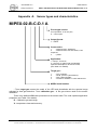
Appendix A. Sensor types and characteristics.
MIPEX-02-B-C-D.1 A
Pins length version:
If not specified - 5.75 mm pins;
A – 4.6 mm pins.
Output format:
1 – UART.
Construction:
1.
- stainless steel, “Standard”;
2.
- stainless steel, with side holes, “Fast
response”;
3.
– plastic.
Application:
I – Group I, for mines;
II – Group II, for places with a potentially
explosive atmosphere, other than mines;
(see Table 3 for details).
Target gas*:
1.
2.
3.
4.
- CH4, methane;
- C3H8, (CnHm, hydrocarbons);
- CO2, carbon dioxide;
- CH4/CH4 +С2Н6 acc. to IEC 60079-29-1
MIPEX model number
* Term target gas means the model of the LED and photodiode with the spectral range
adjusted for best gas detection. Term calibration gas – is the gas mixture used for the sensor
calibration.
There is an additional RX code presented on the sensor label. The code explains application
properties (see Table 3 for details):
R – calibration gas and range;
X - temperature class and accuracy.
File name: ESAT.413347.006 UM v.2.0.docx
Revision 2.0 27 August 2015
Page. 15 of 38
THE SOLE PROPERTY OF OPTOSENSE LLC. ANY REPRODUCTION WITHOUT THE WRITTEN PERMISSION OF OPTOSENSE LLC IS PROHIBITED.
OPTOSENSE LLC
Design Department
USER MANUAL
SMALL-SIZE EXPLOSIVE GAS MEASURING SENSOR MIPEX-02-Х-X-X.1 X
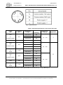
Table 2. MIPEX-02-X-X-X.1 X types and overall dimensions.
File name: ESAT.413347.006 UM v.2.0.docx
Revision 2.0 27 August 2015
Page. 16 of 38
THE SOLE PROPERTY OF OPTOSENSE LLC. ANY REPRODUCTION WITHOUT THE WRITTEN PERMISSION OF OPTOSENSE LLC IS PROHIBITED.
OPTOSENSE LLC
Design Department
USER MANUAL
SMALL-SIZE EXPLOSIVE GAS MEASURING SENSOR MIPEX-02-Х-X-X.1 X
Fig. 1. Sensor pinout.
Table 3. Individual specifications of the sensor (RX code).
Target
gas
Calibration
gas
CH4
or
CH4/СН4+С2H6
CH4
CO2
CO2
CH4
or
CH4/СН4+С2H6
CH4
CH4
or
C3H8
C3H8
CH4
or
CH4/СН4+С2H6
CH4
CO2
CO2
CH4
or
C3H8
C3H8
Measurement
range
RX code
(marking)
0-2.5 % Vol
00
0-5 % Vol
10
0-100 % Vol
20
0-1.5 % Vol
30
0-2.5% Vol
01
0-5 % Vol
11
0-100 % Vol
21
0-1.5 % Vol
61
0-2.5 % Vol
71
0-2.5% Vol
02
0-5 % Vol
12
0-100 % Vol
22
0-1.5 % Vol
32
0-1.5 % Vol
62
0-2.5 % Vol
72
Temperature
range, ⁰C
Application
-10… +40
I
-40… +60
II
-20… +50
Typical sensor sensitivity to other hydrocarbons is shown on Fig. 2, Fig. 3 and Fig. 4.
File name: ESAT.413347.006 UM v.2.0.docx
Revision 2.0 27 August 2015
Page. 17 of 38
THE SOLE PROPERTY OF OPTOSENSE LLC. ANY REPRODUCTION WITHOUT THE WRITTEN PERMISSION OF OPTOSENSE LLC IS PROHIBITED.
OPTOSENSE LLC
Design Department
USER MANUAL
SMALL-SIZE EXPLOSIVE GAS MEASURING SENSOR MIPEX-02-Х-X-X.1 X
Table 4. Response time of the sensors.
Construction
Target gas
Max. response
time t(90), sec
CH4
stainless steel, “Standard” and
plastic
CH4/СН4+С2H6
30
C3H8
CO2
60
CH4
stainless steel, with side holes,
“Fast response”
CH4/СН4+С2H6
10
C3H8
CO2
20
Table 5. General sensor accuracy* depends on calibration gas
Calibration
gas
Accuracy over temperature
range
Additional pressure
error
Additional humidity
error
±0,2% Vol. or ±30% of
indication from
100kPa (test: 80kPa,
100kPa, 120kPa)
±0,2 % Vol. or ±15 %
of indication from the
indication at
adjustment at 40 °C
(test: 20 %RH, 50
%RH,90 %RH)
±0,1% Vol. or ±30% of
indication from
100kPa (test: 80kPa,
100kPa, 120kPa)
±0,1 % Vol. or ±15 %
of indication from the
indication at
adjustment at 40 °C
(test: 20 %RH, 50
%RH,90 %RH)
±0,1%Vol. or ±5% of
indication in range
+20…+25°C;
CH4
±0,2% Vol. or ±10% of
indication in range
–10…+20°C and
+25…+40°C;
±0,4% Vol. or ±20% of
indication in range
-40…-10°C and +40…+60°C.
±0,05% Vol. or ±5% of
indication in range
+20…+25°C;
CO2, C3H8
±0,1% Vol. or ±10% of
indication in range
–10…+20°C and
+25…+40°C;
±0,2% Vol. or ±20% of
indication in range
-40…-10°C and +40…+60°C.
*Table shows the general accuracy, but individual sensor accuracy depends on RX characteristic
and limited by the temperature range (see Table 3).
File name: ESAT.413347.006 UM v.2.0.docx
Revision 2.0 27 August 2015
Page. 18 of 38
THE SOLE PROPERTY OF OPTOSENSE LLC. ANY REPRODUCTION WITHOUT THE WRITTEN PERMISSION OF OPTOSENSE LLC IS PROHIBITED.
OPTOSENSE LLC
USER MANUAL
Design Department
SMALL-SIZE EXPLOSIVE GAS MEASURING SENSOR MIPEX-02-Х-X-X.1 X
150
140
CH4
C3H8
C2H6
C4H10
C6H14
C2H4
Responce concentration, % LEL
130
120
110
100
90
CH4
80
70
60
50
40
30
20
10
0
0
10
20
30
40
50
60
70
80
90
100
Calibrated concentration, % LEL
Fig. 2. Typical sensitivity of MIPEX-02-1-X-X.X X (target and calibration gases – CH4) to other
hydrocarbons.
110
100
Responce concentration, % LEL
90
80
70
C3H8
60
C4H10
50
C5H12
C6H14
40
CH4
30
20
10
0
0
10
20
30
40
50
60
70
80
90
100
Calibrated concentration, % LEL
Fig. 3. Typical sensitivity of MIPEX-02-1-X-X.X X(target and calibration gases – C3H8) to other
hydrocarbons.
File name: ESAT.413347.006 UM v.2.0.docx
Revision 2.0 27 August 2015
Page. 19 of 38
THE SOLE PROPERTY OF OPTOSENSE LLC. ANY REPRODUCTION WITHOUT THE WRITTEN PERMISSION OF OPTOSENSE LLC IS PROHIBITED.
OPTOSENSE LLC
USER MANUAL
Design Department
SMALL-SIZE EXPLOSIVE GAS MEASURING SENSOR MIPEX-02-Х-X-X.1 X
110
Responce concentration, % LEL
100
CH4
C3H8
C2H6
C4H10
C6H14
C2H4
90
80
70
CH4
60
50
40
30
20
10
0
0
10
20
30
40
50
60
70
80
90
100
Calibrated concentration, % LEL
Fig. 4. Typical sensitivity of MIPEX-02-4-X-X.X X(target gas - CH4/СН4+С2H6, calibration gas – CH4)
to other hydrocarbons.
File name: ESAT.413347.006 UM v.2.0.docx
Revision 2.0 27 August 2015
Page. 20 of 38
THE SOLE PROPERTY OF OPTOSENSE LLC. ANY REPRODUCTION WITHOUT THE WRITTEN PERMISSION OF OPTOSENSE LLC IS PROHIBITED.
OPTOSENSE LLC
Design Department
USER MANUAL
SMALL-SIZE EXPLOSIVE GAS MEASURING SENSOR MIPEX-02-Х-X-X.1 X
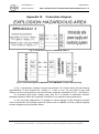
Appendix B. Connection diagram.
Fig. 5. Connection diagram for MIPEX-02-Х-XХ-X.1
Fig. 6 Connection diagram for MIPEX-02 with USB-MIPEX converter during testing.
In Fig. 7 presented an example of sensor connection to “ia” intrinsic safety with the following
characteristics: R value between 25…30Ohm, C = 20uF or over. For any other R more than
30Ohm, use the next equipment to found a minimum necessary capacitance: C(uF) = 2/3*R(Ohm).
For increased input power voltage upper than 5V it is needed to recalculate minimum
allowable resistance which will completely consistent for our explosion safety parameters.
In very low power applications it is possible to reduce leakage current through the diodes
using a micropower shunt voltage reference instead such as LM4040 or similar, protected against
reverse voltages by using Schottky diodes.
File name: ESAT.413347.006 UM v.2.0.docx
Revision 2.0 27 August 2015
Page. 21 of 38
THE SOLE PROPERTY OF OPTOSENSE LLC. ANY REPRODUCTION WITHOUT THE WRITTEN PERMISSION OF OPTOSENSE LLC IS PROHIBITED.
OPTOSENSE LLC
USER MANUAL
Design Department
SMALL-SIZE EXPLOSIVE GAS MEASURING SENSOR MIPEX-02-Х-X-X.1 X
Fig. 7. Example of connecting sensor to “ia” intrinsic safety circuit.
Fig. 8 demonstrates the waveforms of typical MIPEX-02 current consumption and barrier voltage drop with the different values of R. If
capacitor C = 20uF and resistor R = 30Ohm in power supply part of the diagram in Fig. 1, the output voltage of the barrier during the current
pulses are not less than 3.1V, then MIPEX will work properly (without negative influence on performance ). If capacitor C = 20uF and resistor R
= 60 Ohm, the barrier output voltage falls below the minimum supply voltage 3.0V. In this case, the sensor might be unstable.
To prevent MIPEX-02 supply voltage decrease below 3.0V, use following recommendations:
Increasing of barrier supply voltage.
Increase the value of the capacitor in line: i.e. for R = 60 Ohm use capacitor value at least C (uF)~ 2/3 * 60 (Ohm) = 40 uF.
Reduce the value of R (but not less than 25 Ohm, because of limitations Ui=0,25W with 5Vmax).
File name: ESAT.413347.006 UM v.2.0.docx
Revision 2.0 27 August 2015
Page. 22 of 38
THE SOLE PROPERTY OF OPTOSENSE LLC. ANY REPRODUCTION WITHOUT THE WRITTEN PERMISSION OF OPTOSENSE LLC IS PROHIBITED.
OPTOSENSE LLC
USER MANUAL
Design Department
SMALL-SIZE EXPLOSIVE GAS MEASURING SENSOR MIPEX-02-Х-X-X.1 X
Output current of TxD line and the leakage current through the protection diodes contribute to the voltage drop across the resistor R.
In too large output current in TxD circuit it is possible to get the peak output voltage of the barrier below 3.0V, which will cause incorrect
operation of the sensor. To be completely sure, that sensor will be powered properly, we recommend to check supply voltage using oscilloscope
while working with your device.
Fig. 8. Diagrams of typical MIPEX-02 current consumption and barrier voltage drop.
File name: ESAT.413347.006 UM v.2.0.docx
Revision 2.0 27 August 2015
Page. 23 of 38
THE SOLE PROPERTY OF OPTOSENSE LLC. ANY REPRODUCTION WITHOUT THE WRITTEN PERMISSION OF OPTOSENSE LLC IS PROHIBITED.
OPTOSENSE LLC
Design Department
USER MANUAL
SMALL-SIZE EXPLOSIVE GAS MEASURING SENSOR MIPEX-02-Х-X-X.1 X
Appendix C. UART communication protocol.
Firmware release 25.6
Always check the command syntax before sending. The commands, other than
specified in user manual are not allowed. Otherwise it might bring to malfunction of
the sensor.
In earlier firmware versions some commands/modes are not available.
C.1.
General information
Sensor communication protocol provides data exchange based on “Request-Response”
principle.
Sensor has fix 9600 baud rate
Electrical parameters of UART-transceiver are pointed in 5.2.3.
Data format: 8-bit message, 1 stop bit, no parity.
Frame format (if other is not specified):
-
the symbols of commands are in ASCII,
carriage return (CR) symbol must be after each command,
all symbols in the commands must be sent in one word. Delay between symbols are not
more than 40 ms.
The words of the response are separated with a tabulation symbol (09h) or space symbol
(20h) (specified below for every command). For some commands request is not intended to
answer according to following protocol. Sensor returns confirmation or rejection of command.
Request on correct command with correct data returns command name with OK separated by
(09h) or (20h). Request on correct command with wrong data returns command name with FAULT
separated by (09h) or (20h). There is no reaction on wrong command.
C.2.
Work modes
There are two modes of sensor’s work – OEM and USER. OEM mode is intended to display
information and make calibrations and setup. USER mode is intended to display information only.
Calibration in USER mode is unavailable.
Send command UART? to check current sensor mode (see Table 10).
C.3.
Protocol commands
C.3.1.
Operating commands
Data request commands are the basic sensor functionality and contained various
combinations of parameters, such as concentration, temperature, sensor condition and status. The
shortest command of the protocol is @. It includes the gas concentration only. The most detailed
request is F, which contains a data, calculated during the sensor operating.
Detailed information about the operating commands is shown in Table 6.
File name: ESAT.413347.006 UM v.2.0.docx
Revision 2.0 27 August 2015
Page. 24 of 38
THE SOLE PROPERTY OF OPTOSENSE LLC. ANY REPRODUCTION WITHOUT THE WRITTEN PERMISSION OF OPTOSENSE LLC IS PROHIBITED.
OPTOSENSE LLC
USER MANUAL
Design Department
SMALL-SIZE EXPLOSIVE GAS MEASURING SENSOR MIPEX-02-Х-X-X.1 X
Table 6. Sensor operating commands
Command in
OEM mode
Available in
USER mode
@
Yes
Requests of concentration.
see Table 8
@*X
Yes
Periodical request of concentration.
see Table 8
DATA
Yes
Request concentration readings.
Command name
Response
ASCII 5digits and
0Dh
Description
Response in HEX. The command @ is 16-bit concentration data. The
lead byte Conc1H transmitted first, low byte Conc1L at the end of
response.
Response in HEX. The command @*X is initiate regular transmitting
of gas concentration data to UART. Here X - is a value in range 0…9
(ASCII) proportion to standard operating period of the sensor (1.3
sec).
The response is the concentration in %Vol * 100. i.e. response 00198
means 1.98%Vol.
DATAE
Yes
Request concentration, status byte
and check sum.
HEX 4-bytes
and 0Dh
Bytes #1…2 are the concentration data (similar to @-response), byte
#3 is the status byte, byte #4 - ControlSum^EveryByte.
DATAE2
Yes
Request concentration, double status
byte and check sum. Response in
HEX.
HEX 6-bytes
and 0Dh
Bytes #1…2 are the concentration data (similar to @-response),
bytes #3…4 are the status bytes, byte #5 - ControlSum^EveryByte.
CCS
Yes
Request of concentration,
temperature in Celsius degrees and
status word.
ХХХХХ
YYYYY
ZZZZZ
ХХХХХ YYYYY ZZZZZ separated with space symbol (20h) in ASCII.
ХХХХХ is gas concentration, YYYYY is temperature value in Celsius,
ZZZZZ is the status byte (see Table 9)
CFS
Yes
Request concentration, temperature
in Fahrenheit degrees and status
word.
CKS
Yes
Request concentration, temperature
in Kelvin degrees and status word.
ХХХХХ
YYYYY
ZZZZZ
ХХХХХ
YYYYY
ZZZZZ
CONST
No
CONST2
No
ХХХХХ YYYYY ZZZZZ separated with space symbol (20h) in ASCII.
ХХХХХ is gas concentration, YYYYY is temperature value in
Fahrenheit, ZZZZZ is the status byte.
ХХХХХ YYYYY ZZZZZ separated with space symbol (20h) in ASCII.
ХХХХХ is gas concentration, YYYYY is temperature value in Kelvin,
ZZZZZ is the status byte.
The response includes the constants stored in sensor memory and
used for troubleshooting. The response format available by request.
See chapter C.5 for details.
F
Yes
Request of sensor constants.
Request of sensor constants from the
special memory space.
Detailed information about working
condition of the sensor.
File name: ESAT.413347.006 UM v.2.0.docx
see Table 7
Revision 2.0 27 August 2015
Response on F command is 5 byte in ASCII separated by (09h).
Page. 25 of 38
THE SOLE PROPERTY OF OPTOSENSE LLC. ANY REPRODUCTION WITHOUT THE WRITTEN PERMISSION OF OPTOSENSE LLC IS PROHIBITED.
OPTOSENSE LLC
USER MANUAL
Design Department
SMALL-SIZE EXPLOSIVE GAS MEASURING SENSOR MIPEX-02-Х-X-X.1 X
Table 7. Structure of F command response
Byte number
Byte data
Data description
1
0Eh
2-6
Termo
7
09h
Tabulation
8-12
<St>
Ratio Us/Uref with temperature index
13
09h
Tabulation
14-18
Us
Operating signal in ADC readings
19
09h
Tabulation
20-24
Uref
Reference signal in ADC readings
25
09h
Tabulation
26-30
Stz0
Ratio <Stz> with manual zeroing settings (ZERO)
31
09h
Tabulation
32-36
Stz
Ratio Stz0 with drift compensation algorithm
37
09h
Tabulation
38-42
Stzkt
Ratio Stz with coefficient of temperature sensitivity
43
09h
Tabulation
44-48
Conc
49
09h
50-54
Conc1
55
09h
56-60
Status
61
09h
Tabulation
62-71
Sn
Sensor serial number
70
09h
Tabulation
71
ControlSum
72
09h
Tabulation
73
0Dh
Carriage return
Special character
Sensor temperature in ADC readings
Concentration (according to a factory calibration)
Tabulation
Concentration scaled by user
Tabulation
Status word (see Table 9)
Checksum based on XOR
Table 8. Structure of @ and @*X commands
Command @ (40h 0Dh)
response, byte number and data
Command @*x (40 2A x 0D) response, byte number
and data
1
2
1
2
3
Conc1H
Conc1L
@(40h)
Conc1H
Conc1L
File name: ESAT.413347.006 UM v.2.0.docx
Revision 2.0 27 August 2015
Page. 26 of 38
THE SOLE PROPERTY OF OPTOSENSE LLC. ANY REPRODUCTION WITHOUT THE WRITTEN PERMISSION OF OPTOSENSE LLC IS PROHIBITED.
OPTOSENSE LLC
USER MANUAL
Design Department
SMALL-SIZE EXPLOSIVE GAS MEASURING SENSOR MIPEX-02-Х-X-X.1 X
Table 9. Status word description
Status word
Status
byte L
(DATAE or
DATAE2)
Status
byte H
(DATAE or
DATAE2)
00
10
Description
Recommendation
Normal mode, static temperature
Bit 0
11
Bit 0
Warm-up
Do not perform calibration.
Too many UART interruptions
Do not perform calibration or zeroing. Decrease request frequency.
21
Bit 4
Fast temperature change
Do not perform calibration or zeroing.
22
Bit 5
Sharp temperature change
Do not perform calibration or zeroing.
24
Bit 4
Fast temperature change + Zero
shifts to negative values
Do not perform calibration or zeroing.
Low signals level
Do not perform calibration or zeroing.
Measuring accuracy need to be additionally verified, once
switching on of Bit 2 has been observed.
Replace the sensor if Bit2 is on constantly (> 20 min).
Zero shifts to negative values
Using of dust filters is recommended to avoid moisture or dust
inside sensor. In case of moisture ingress, unmounts sensor off
device, then dry it during 4 hours minimum in warm dry location.
Make zeroing procedure and performance check.
Out of operation temperature range
Check the ambient temperature.
Abrupt change of signal
Do not perform calibration or zeroing.
Replace sensor, if bit1 is on constantly (> 20 min).
Complex status
Contact support for details
Firmware corruption
Contact support for details
Low power mode is on. XX- status
word values similar for normal mode.
To achieve full compliance to declared specification turn on the
standard mode
30
Bit 1
Bit 2
31
Bit 1
40
Bit 6
50
Bit 1
51
90
1XX
Bit 7
Bit 2
File name: ESAT.413347.006 UM v.2.0.docx
Revision 2.0 27 August 2015
Page. 27 of 38
THE SOLE PROPERTY OF OPTOSENSE LLC. ANY REPRODUCTION WITHOUT THE WRITTEN PERMISSION OF OPTOSENSE LLC IS PROHIBITED.
OPTOSENSE LLC
USER MANUAL
Design Department
SMALL-SIZE EXPLOSIVE GAS MEASURING SENSOR MIPEX-02-Х-X-X.1 X
C.3.2. Request commands of factory settings and properties.
The commands shown in Table 10 are used for sensor setup, check the factory settings and firmware update.
There is able to work with up to 256 sensors in one UART line. Use prefix #XX before any command to send commands to any sensor in
one UART line. XX is a network hexadecimal address from 00 to FF.
Table 10. Setting commands
Command in
OEM mode
Available in
USER mode
LOWPWx
No
Setup power mode.
LOWPW?
No
Check the current sensor mode.
OEM XXXX
Yes
Change mode from USER to OEM.
USER
PASS XXXX
YYYY
Yes
Change mode from OEM to USER.
Command name
No
Password change.
DATEZC
DD.MM.YY
No
Write calibration date in format
DD.MM.YY.
DATEZC?
Yes
Check calibration date.
Response
Description
LOWPWx
OK
HI or LW
USER or
OEM
USER
PASS XXXX
YYYY OK
DATEZC
DD.MM.YY
OK
DD.MM.YY
x = 0 – normal mode of power consumption (HI), х = 1 – low power
consumption mode (LW).
CRC
Yes
Firmware integrity check, calculated
according to CRC16 algorithm.
CRC OK and
XXXXX
YYYYY OK
ID?
Yes
Check identifier.
TYPE SN RX
SREV
INDSIG ON
No
INDSIG OFF
No
Turn on negative shift indication in
concentration readings.
Turn off negative shift indication in
concentration readings.
File name: ESAT.413347.006 UM v.2.0.docx
ON
OFF
Revision 2.0 27 August 2015
XXXX is digital password. If the password not correct, sensor stay in
current mode.
XXXX is old password, YYYY is new password. By default the
password is ‘’0000’’.
DD – day (1-31), MM – month (1-12), YY – year (00 – 99).
After time-out during the calculations, not more than 1 sec). XXXXX –
calculated checksum for current firmware, YYYYY– checksum stored in
memory of the sensor. In case of malfunction, XXXXX and YYYYY
values does not match together. Status word indicates 90 value if CRC
mismatches.
Returns summary info about type code, serial number, RX code and
firmware version separated with space symbol.
The command activates the possibility to show concentration shift to
negative values. In case of using this command, response on
concentration request is -2 (status word 31) or -3 (status word 24) in
ASCII. It is not needed to activate mode after power reset.
Page. 28 of 38
THE SOLE PROPERTY OF OPTOSENSE LLC. ANY REPRODUCTION WITHOUT THE WRITTEN PERMISSION OF OPTOSENSE LLC IS PROHIBITED.
OPTOSENSE LLC
USER MANUAL
Design Department
SMALL-SIZE EXPLOSIVE GAS MEASURING SENSOR MIPEX-02-Х-X-X.1 X
Check the type code (TYPE)
ASCII 5-byte
and 0Dh
Check the characteristics code
(RX).
Check the sensor serial number
(SN).
ASCII 2-byte
and 0Dh
ASCII 8 byte
and 0Dh
RT?
Yes
RX?
Yes
SRAL?
Yes
SREV?
Yes
Check the firmware version.
SREVH
No
History request of firmware
updates.
USERDATA?
No
Display all data stored in memory.
Stacked 10
digits shows
No
Check data in the sensor memory.
Value from
00 to 09
USERDATA
XX?
USERDATA
XX YYYYY
NETON
NETOFF
!**
%XXYY
No
Save data to the sensor memory.
YYYYY
No
No
No
Yes
Enable to storing network address
Disable address storing.
Check current network address.
Set up network address.
UART?
Yes
Request current work mode.
NETON OK
NETOFF OK
XX
YY
USER or
OEM
UPLOAD
No
Switch the sensor to firmware
update bootloader mode.
File name: ESAT.413347.006 UM v.2.0.docx
U_OK
Revision 2.0 27 August 2015
The response includes the sensor type data (MIPEX model, target gas,
housing code and pinout code). The response format available by
request.
RX codes according to Table 3.
Response includes the sensor model and current firmware version. For
example: MIPEX-2_25.4
The command response is the 10 latest firmware versions. Example of
response – see chapter C.4.
There is ability to save up to 10 digits (0-99999) to flash-memory of the
sensor. After firmware update from the 25.2 version, where this function
is absent, all default values are «67294».
Display the data saved in cell with ХХ number.
Save YYYYY value to cell number ХХ.
After turn off power, net address will be reserved.
After turn off power, net address will be erased (default 00 value).
Response is network hexadecimal address
XX – old address, YY – new address.
See chapter C.4 for details.
Page. 29 of 38
THE SOLE PROPERTY OF OPTOSENSE LLC. ANY REPRODUCTION WITHOUT THE WRITTEN PERMISSION OF OPTOSENSE LLC IS PROHIBITED.
OPTOSENSE LLC
USER MANUAL
Design Department
SMALL-SIZE EXPLOSIVE GAS MEASURING SENSOR MIPEX-02-Х-X-X.1 X
C.3.3. Sensor setting and calibration commands
The commands shown in Table 11 are used during sensor calibration. The procedure and used equipment described in Sensor zeroing.
Table 11. Calibration and zeroing commands
Command in
OEM mode
Available in
USER mode
AZERO ON
No
AZERO OFF
Command name
Response
Description
Turn on autozeroing algorithm.
AZERO ON
No
Turn off autozeroing algorithm.
AZERO OFF
AZERO?
No
Check current autozeroing status.
AZERO ON or
AZERO OFF
CALB AAAA
No
Span gas calibration.
CALB AAAA
OK or CALB
AAAA FAULT
From the firmware ver.2x.6 introduced new autozeroing algorithm
and the possibility to adjust the temperature coefficients by user.
Autozeroing is embedded in self-diagnostics algorithm of the sensor.
It starts after sensor is powered up. Self-diagnostics is operating
during the sensor is on. If anyway, zero shift is observed, manual
zeroing procedure is recommended.
AAAA is CGM concentration value in %Vol.*100. For example,
AAAA=0198 corresponds to 1,98 %Vol. Entered value must not be
different from current readings more than 20 times with regard to all
units converted to %Vol. CGM concentration must be more than
0,2% Vol. If these conditions are not accomplished, sensor responds
CALB AAAA FAULT. Scaling procedure should be used for following
purpose:
- Quick switch between readings in % vol. or % LEL.
- Setup known cross-coefficients for measuring other heavy
hydrocarbons gases (CnHm).
CALB1
XXXXX
No
CALB2
XXXXX
No
CALB3
XXXXX
No
Write scale coefficient for
concentration for range 0-5% Vol.
(CH4).
Write scale coefficient for
concentration range 5-100% Vol.
(CH4).
Write scale coefficient for whole
concentration range 0-100% Vol.
(CH4).
File name: ESAT.413347.006 UM v.2.0.docx
CALB1 XXXX
OK
CALB2 XXXX
OK
XXXXX – value of scale coefficient, 10000 corresponds to unitary
coefficient.
CALB3 XXXX
OK
Revision 2.0 27 August 2015
Page. 30 of 38
THE SOLE PROPERTY OF OPTOSENSE LLC. ANY REPRODUCTION WITHOUT THE WRITTEN PERMISSION OF OPTOSENSE LLC IS PROHIBITED.
OPTOSENSE LLC
USER MANUAL
Design Department
SMALL-SIZE EXPLOSIVE GAS MEASURING SENSOR MIPEX-02-Х-X-X.1 X
SETC XXXXX
No
One-point temperature calibration.
SETC XXXXX
OK
ZERO
No
Setting zero in current temperature.
ZERO OK
ZERO
XXXXX
YYYYY
No
Manual setting of temperature
coefficients.
ZERO2
No
Setting zero in whole operating
temperature range.
ZERO2 OK
INIT
No
Restore to factory default.
INIT OK or
INIT FAULT
File name: ESAT.413347.006 UM v.2.0.docx
ZERO
XXXXX
YYYYY OK
Revision 2.0 27 August 2015
XXXXX – temperature in Celsius degrees. With SETC command,
sensor stores in memory the ambient temperature value. Also see
CCS, CFS, CKS command description.
Command allows to set zero in different points of operating
temperature range. See detailed procedure below.
XXXXX – temperature data, YYYYY – signal ratio <Stz>.
The command initiate calculation and store a unifying zero coefficient
to the memory. In case of supplying this command, concentration
Conc = 0, Conc1 = 0, relation Stz is corrected to 10000 (see Table
7).
The command is used in case of wrong sensor calibration or other
improper actions over the sensor.
Page. 31 of 38
THE SOLE PROPERTY OF OPTOSENSE LLC. ANY REPRODUCTION WITHOUT THE WRITTEN PERMISSION OF OPTOSENSE LLC IS PROHIBITED.
OPTOSENSE LLC
Design Department
C.4.
USER MANUAL
SMALL-SIZE EXPLOSIVE GAS MEASURING SENSOR MIPEX-02-Х-X-X.1 X
Firmware update
Firmware update must be proceed with accordance to following description.
Optosense LLC disclaims all liability for sensor malfunction due to mistakes
committed by user during firmware update.
Firmware version 24.6 is compatible with previous version 24.2 for MIPEX02-3-X-X.1 X (СО2) only.
Firmware version 25.6 is compatible with previous versions 25.2 and 25.4 for
MIPEX-02-1-X-X.1 X (CH4), MIPEX-02-2-X-X.1 X (С3H8), MIPEX-02-4-X-X.1
X (CH4/CH4 +С2Н6) only.
The term «compatible» means that sensor performance as well as protocol
commands of previous versions keeps unchanged after finishing of firmware update
process.
To update sensor firmware use the following procedure and commands:
Send SREV? command and check that current version is able to be updated. If firmware
version is 25.4, make sure that sensor is in OEM mode by sending UART?.
Send UPLOAD and receive U_OK response. Sensor switched to bootloader.
Upload firmware to sensor memory. It is necessary to make “Erase pages” before loading
application code. Page quantity corresponds to code file size in Kbytes.
Do not use “Mass erase” in bootloader, it will clear all memory and leads to sensor
malfunction.
Verify uploaded firmware code. Use “Read memory” command of bootloader.
Turn off the power of sensor and then turn it on. If “Jump to user code” function has been
used in bootloader mode to switch the sensor power is not necessary.
Description and example of procedure using PC, MIPEX evaluation kit and
STMicroelectronics flash loader software could be found in archive with new
firmware.
More details about algorithms and protocol in bootloader mode could be
found in the documentation “AN2606 Application note STM32™
microcontroller system memory boot mode”.
For MIPEX-02-3-X-X.1 X (СО2) proceed sending ZERO2 only with nitrogen
feeding.
File name: ESAT.413347.006 UM v.2.0.docx
Revision 2.0 27 August 2015
Page. 32 of 38
THE SOLE PROPERTY OF OPTOSENSE LLC. ANY REPRODUCTION WITHOUT THE WRITTEN PERMISSION OF OPTOSENSE LLC IS PROHIBITED.
OPTOSENSE LLC
Design Department
C.5.
USER MANUAL
SMALL-SIZE EXPLOSIVE GAS MEASURING SENSOR MIPEX-02-Х-X-X.1 X
Troubleshooting
In case of malfunctions or errors of sensor do following steps:
1. Send in OEM mode sequence of commands F, SREVH, CONST, CONST2 in ASCII;
2. Save responses in log-file;
3. Send this log-file with comments via e-mail [email protected].
Example of log-file listing obtained by MIPEX ETS:
Port: COM3
SN: 08065278
Type: MIPEX-2_25.6
================
Sending:
> #00UART?
<< OEM
>F
<< 01665 10042 08482 07981 10002 10000 10000 00000 00000 00000 08065278
> SREVH
<< MIPEX-2_2506
MIPEX-2_2504
MIPEX-2_0000
MIPEX-2_0000
MIPEX-2_0000
MIPEX-2_0000
MIPEX-2_0000
MIPEX-2_0000
MIPEX-2_0000
MIPEX-2_0000
> CONST
<< 10000 09829 10454 08035278 00000 001485 -00005 -00010 00200 01671 00772 01588 00020 00015
00120 00020 00060 0000000000 06900 00500 00800 08948 10000
00412 03400 00100 00200 10002
> CONST2
<< 10000 09829 10454 08035278 00000 001485 -00005 -00010 00200 01671 00772 01588 00020 00015
00120 00020 00060 0000000000 06900 00500 00800 08948 10000
00412 03400 00100 00200 10002
File name: ESAT.413347.006 UM v.2.0.docx
Revision 2.0 27 August 2015
Page. 33 of 38
THE SOLE PROPERTY OF OPTOSENSE LLC. ANY REPRODUCTION WITHOUT THE WRITTEN PERMISSION OF OPTOSENSE LLC IS PROHIBITED.
OPTOSENSE LLC
Design Department
USER MANUAL
SMALL-SIZE EXPLOSIVE GAS MEASURING SENSOR MIPEX-02-Х-X-X.1 X
Appendix D. Sensor zeroing and calibration.
1. Closing gas-sampling holes of the sensor impairs response time.
2. Do not zeroing under span gas concentration.
3. Recommended zero-gas is nitrogen or clean air (no impurities).
4. Always make manual zeroing after sticking (or removing) the dust filter on the
sensor.
5. To achieve correct data during the tests, be sure there are no:
excessive force on sensor housing,
100% humidity (dewpoint),
out of specified range of environmental pressure,
fast temperature change (more than 0.6 ⁰ C/min), dust (if dust filter is not
used),
sensor rate no more than 1Hz.
The setting of zero and calibration of the sensor is performed in the course of the primary
installation into a gas analyzer as well as annually during preparation to conducting a check. In any
cases the setting zero should be done before calibration.
The devices given in Fig. 9 and the CGM are used in the course of conducting operations.
The operations on setting zero and calibration of the sensor shall be carried out by a
qualified specialist outside of the explosion-hazardous zone at normal conditions.
Gas adapter
CGM
USB cable
PC
PC
USB converter
Fig. 9 Typical scheme of MIPEX-02 calibration
D.1.
Zeroing
D.1.1. Autozero.
Autozeroing is embedded in self-diagnostics algorithm of sensor. It starts after sensor is
powered up. Self-diagnostics is operating all along during the sensor is on. If anyway, zero shift is
observed, manual zeroing procedure is recommended.
File name: ESAT.413347.006 UM v.2.0.docx
Revision 2.0 27 August 2015
Page. 34 of 38
THE SOLE PROPERTY OF OPTOSENSE LLC. ANY REPRODUCTION WITHOUT THE WRITTEN PERMISSION OF OPTOSENSE LLC IS PROHIBITED.
OPTOSENSE LLC
Design Department
USER MANUAL
SMALL-SIZE EXPLOSIVE GAS MEASURING SENSOR MIPEX-02-Х-X-X.1 X
D.1.2. Manual zeroing in whole temperature range.
1.
Fill up the sensor with zero-gas.
2.
Send DATAE and check, that status byte in response is 0.
3.
Send ZERO2 command in ASCII and check, that response is ZERO2 OK.
D.1.3. Manual zeroing in different points of temperature range.
If zero shift appears in different temperature, use ZERO command with following
recommendations.
Procedure is similar to manual zeroing in whole temperature range and consists ZERO
command sending in various static temperatures, i.e. after status byte in response of DATAE is 0.
There are three ways to make this procedure:
One point zeroing. Send ZERO command in any static temperature. That is recommended to
take a temperature point close to 23 ⁰С.
Three points zeroing. Taking one point at 23 ⁰C and two others close to edges of operating
temperature range is recommended.
Multipoint zeroing. That is recommend to take one point at 23 ⁰C, two points at the edges of
operating temperature range and some other intermediate points. Similar, 10-13 ⁰С - fold interval
should be taken between each points.
Because of MIPEX-02-X-II-X.1 X temperature range could be divided on 8 interval, most time
taking, but most precise procedure is 9-point zeroing.
Fig. 10. Scheme of manual zeroing with ZERO command.
If the requirements to the sensor error are not fulfilled in accordance with Table 5, the
procedure of setting zero and calibration shall be repeated. In case of a repeated non-compliance
of the sensor readings to the value of concentration of СGM No.3, the sensor is subject to
replacement and dispatching to the Manufacturer.
D.2.
Scaling
Scaling procedure should be used for following purpose:
Quick switch between readings in % vol. or % LEL.
Set up cross-coefficients for measuring other hydracarbons gases, than calibrated
one. Cross-coefficients can be requested as additional option by ordering. Please
note, that accuracy in this case is lower than specified.
There are two scale coefficients for CH4-sensors. First is for 0-5%Vol. range. Second
is for 5-100%Vol. range.
File name: ESAT.413347.006 UM v.2.0.docx
Revision 2.0 27 August 2015
Page. 35 of 38
THE SOLE PROPERTY OF OPTOSENSE LLC. ANY REPRODUCTION WITHOUT THE WRITTEN PERMISSION OF OPTOSENSE LLC IS PROHIBITED.
OPTOSENSE LLC
Design Department
USER MANUAL
SMALL-SIZE EXPLOSIVE GAS MEASURING SENSOR MIPEX-02-Х-X-X.1 X
Proceed operations pointed below as**, only if sensor has 0-100 % Vol. measuring
range or up to 100%Vol. indication range.
Use the following sequence to make scaling:
1. Send DATAE and check, that status byte in response is “0”.
2. To set up the first coefficient send CALB1 XXXXX command in ASCII and check, that
response is CALB1 XXXXX OK. Where XXXXX is scaling coefficient, i.e. 20000.
3. ** To set up the second coefficient send CALB2 YYYYY command in ASCII and
check, that response is CALB2 YYYYY OK.
By default, scaling coefficients are XXXXX=YYYYY=10000, that means of no scaling. Do not
apply span gas while scaling.
For example, if it is needed to get readings of CH4 in %LEL, normalized to 1000 (reading
1000 corresponds to 100% LEL of CH4) send CALB1 20000.
Use the following sequence to span gas calibration procedure:
1. Make Manual zeroing procedure.
2. Fill up the sensor with span gas in the range up to 5%Vol (recommended in mid of
range, e.g. 2.5% Vol. CH4).
3. Wait until status byte becomes “0” and gas reading stabilized, sending DATAE
commands and checking their responses.
4. Send CALB AAAA command in ASCII (43h; 41h; 4Ch; 42h; 20h; AAh; AAh; AAh;
AAh; 0Dh in HEX), where AAAA is gas concentration, normalized to 1000 (i.e.
AAAA=0250 for 2.5% Vol CH4). Span gas concentration must be more than 0.1%
Vol. Otherwise the sensor will return FAULT in response. Check, that response is
CALB AAAA OK.
5. Repeat operations in items 3… 4 of current procedure with span gas in range of 5100%Vol (recommended in mid of range, e.g. 50% Vol CH4), if sensor has
measurement range up to 100% vol. CH4. No need to calibrate second range, it is
out of use.
List of CGM used for checking IR gas sensors MIPEX-02
The recalculation to % of LEL shall be effected in accordance with the following formula for
concentration expressed in volume fraction, vol. %:
LFSCL
100 C
;%
C h
where
LFSCL is % LEL
С – component content in volume fraction, vol. %;
С(h) – LEL of component, % (constant);
С(h) = 4.4 % – for methane;
С(h) = 1.7 % – for propane.
File name: ESAT.413347.006 UM v.2.0.docx
Revision 2.0 27 August 2015
Page. 36 of 38
THE SOLE PROPERTY OF OPTOSENSE LLC. ANY REPRODUCTION WITHOUT THE WRITTEN PERMISSION OF OPTOSENSE LLC IS PROHIBITED.
OPTOSENSE LLC
Design Department
USER MANUAL
SMALL-SIZE EXPLOSIVE GAS MEASURING SENSOR MIPEX-02-Х-X-X.1 X
Table 12. CGM used for CH4 calibration gas.
CGM Nos
according
to text
Component
composition
Composition
of measured
component,
vol. %,
(% of LEL)
Permissible
deviation
limits, vol. %
Limits of
permissible
error of
qualification,
vol. %
Number as per
State Register
or Standard
designation
1
N2
100
-
-
GOST
9392-74
2
СН4 – N2
2,2 (50)
±0,25
±0,04
3883-87
3
СН4 – N2
4,15 (94)
±0,25
±0,04
3883-87
Table 13. CGM used for C3H8 calibration gas.
CGM Nos
according
to text
Component
composition
Composition
of measured
component,
vol. %,
(% of LEL)
Permissible
deviation
limits, vol. %
Limits of
permissible
error of
qualification,
vol. %
Number as per
State Register
or Standard
designation
1
N2
100
-
-
GOST
9392-74
2
С3Н8 – N2
0,85 (50)
±0,05
±0,015
5328-90
3
С3Н8 – N2
1,6 (94)
±0,1
±0,05
EM 06.01.648
Table 14. CGM used for CO2 calibration gas.
CGM Nos
according
to text
Component
composition
Composition
of measured
component,
vol. %,
(% of LEL)
Permissible
deviation
limits, vol. %
Limits of
permissible
error of
qualification,
vol. %
Number as per
State Register
or Standard
designation
1
N2
100
-
-
GOST 9392-74
2
СО2 – N2
1
±0,05
±0,015
3
СО2 – N2
2.5
±0,1
±0,05
File name: ESAT.413347.006 UM v.2.0.docx
Revision 2.0 27 August 2015
Page. 37 of 38
THE SOLE PROPERTY OF OPTOSENSE LLC. ANY REPRODUCTION WITHOUT THE WRITTEN PERMISSION OF OPTOSENSE LLC IS PROHIBITED.
OPTOSENSE LLC
Design Department
USER MANUAL
SMALL-SIZE EXPLOSIVE GAS MEASURING SENSOR MIPEX-02-Х-X-X.1 X
Appendix E.
Dust filters.
The dust filters are available on special request. For the “Standard” and “Plastic” housings is
used Top filter ESAT.717100.001 only (see Fig. 11). For the “Fast response” modification is used
additional Side filter ESAT.717100.002 (see Fig. 12). The filters material - Membrane Владипор
МФФК ТУ 6-55-221-1413-2004. On the dark areas applied 3M Double Linered Laminating
Adhesive 7952.
Fig. 11. Top filter for the "Standard" and "Plastic" housings.
Fig. 12. Side filter for the "Fast response" housing.
To attach the dust filter, perform the following steps:
Perform this work at well illuminated and well ventilated place.
After attaching the dust filter, perform zeroing procedure (see Appendix
D for details).
Wipe the sensor top surface with a cloth that is dampened with absolute alcohol.
For the “Fast response” modification, perform the same operation on the side surface.
Retrieve the teflon tape-bonded dust filters from packing.
Detach a filter from the teflon tape with tweezers.
Align the filter to the top surface center with tweezers, and then press on it.
For the “Fast response” modification, perform the same operation on the side surface.
After the dust filter was attached, zeroing procedure must be performed (see Appendix D for
details).
File name: ESAT.413347.006 UM v.2.0.docx
Revision 2.0 27 August 2015
Page. 38 of 38
THE SOLE PROPERTY OF OPTOSENSE LLC. ANY REPRODUCTION WITHOUT THE WRITTEN PERMISSION OF OPTOSENSE LLC IS PROHIBITED.