1
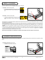
MANUBAL
C40
User Manual
Read carefully before operating
the Manubal bale grab
UK 365080 AA - 0511
Original instructions
Dear user,
We thank you for placing your trust in our product and hope you will find your MX MANUBAL satisfactory in
every way.
Taking a few minutes to read this manual will enable you to use the capabilities of your MX MANUBAL to the
full, prolong its service life and ensure safe operation.
The MANUBAL user manual before you is an important document, please retain it in order to be able to refer
to it if required. Make it available to any other users and hand it over it to any new owner in the event of your
MX MANUBAL being sold on.
The illustrations and technical data shown in this document might not match your MX MANUBAL bale grab
exactly, operating conditions will nevertheless remain the same.
The user must read and understand this manual
before first use.
TABLE OF CONTENTS
Page
1. SAFETY RULES
5
2. SAFETY STICKERS
6
3. IDENTIFICATION PLATE
6
4. HITCHING THE MANUBAL
7
5. UNHITCHING THE MANUBAL
8
6. ADJUSTING THE MANUBAL ACCORDING TO THE BALE DIAMETER
9
7. POWER CONTROL SYSTEM
9
8. MAINTENANCE / STORAGE
10
9. TECHNICAL SPECIFICATIONS
10
EC DECLARATION OF CONFORMITY
1. SAFETY RULES
The tractor/loader or telescopic handler/MANUBAL bale grab combination must only be operated by trained and
experienced personnel.
— For your complete safety and that of others, strict compliance with the hitching and unhitching procedure for
the MANUBAL bale grab is required (chapter 5 of this manual).
— Only control the MANUBAL bale grab from the driver's seat. Keep operating the controls until movements stop.
— Do not leave the driver's seat without stopping all control movements.
— All personnel must be kept away from the area in which the loader or telescopic handler - MANUBAL bale grab
combination is moving while it is in operation.
— Never pass under a raised bale. Never use the MANUBAL bale grab to push a bale.
— Carrying or lifting personnel using the MANUBAL bale grab is forbidden. Never stand or pass under the load.
— Before any operation, the user must ensure that the MANUBAL bale grab is in proper working order and can be used
in complete safety. He must also check and ensure that the tractor-loader-MANUBAL bale grab combination is stable
by fitting a counterweight to the back of the tractor. This should ensure that 20% of gross weight remains on the rear
axle of the tractor for optimum safety while travelling and working.
— When travelling on the road it is imperative that the regulations governing use on the public highway be observed
(size, implement markings, etc.) The grab must be closed.
— Take great care when operating at height in order to avoid catching any items (electric power or telephone lines,
guttering, roof trusses, etc.).
— Whenever the tractor or telescopic handler is stopped momentarily or for an extended period, the engine must be shut
down and the MANUBAL bale grab lowered.
— Check periodically to ensure that safety pins and bolts are in place. Do not replace them with any other items such
as: nails, wire, etc.
— Any adjustment on the MANUBAL bale grab (position of the backplate tubes, Power Control System adjustment, ...)
must be carried out after the MANUBAL bale grab has been lowered to the ground and the tractor or telescopic
handler engine shut down.
— Any work involving fault tracing (diagnostics) and/or disassembly of parts may only be undertaken by a skilled
technician who will start with an assurance that the work will be carried out in complete safety for himself and his
surroundings.
Caution!
— Check hoses for length and routing in all configurations (fully crowded, fully dumped, etc.) before first use.
— The MANUBAL bale grab is designed to withstand a maximum operating pressure of 210 bar. Above this pressure,
the MANUBAL bale grab will require to be fitted with a pressure limiter.
— Any instance of a MANUBAL bale grab being fitted which ignores the recommendations in the MX price list in force
on the date of purchase will void MX warranty on the entire supply.
— Any modification to any part of the MX supply (rams, grab, tines, crank, etc.) or use of a component installed on the
MANUBAL bale grab which has not originated from MX will void MX warranty on the entire MX supply.
— Use only genuine MX spare parts. Do not modify your MANUBAL bale grab yourself or have it modified by anyone
else, without first requesting written authorisation from MX. Failure to comply with these rules may render your
MANUBAL bale grab hazardous. In the event of damage or injury, MX shall not be held responsible in any way.
— Warranty cover will cease immediately in the event of failure to observe the standards and instructions for use and
maintenance of the MANUBAL bale grab as stipulated in the user manual.
THE INSTALLER SHALL BE FULLY LIABLE FOR ANY FITMENT ON A LOADER OTHER THAN MX OR A TELESCOPIC
HANDLER WHICH HAS NOT BEEN RECOMMENDED BY MX.
• 19, rue de Rennes • BP 83221 • F - 35690 ACIGNÉ
5
Modification reserved
2. SAFETY STICKERS
Ensure the labels are clean and legible; replace them if damaged.
1. Location : exterior left-hand side.
— Familiarise yourself with the safety rules in the
user manual before using or working on the
unit.
2
2. Location : exterior left-hand side.
— Familiarise yourself with the safety rules in the
user manual before using or working on the
unit.
1
MX implements are designed to offer the operator of the prime mover to which they are fitted optimum angles for crowding
and dumping at ground level.
Before handing over to the operator, the installer must check that there is no possibility of interference occurring between
the implement which has been fitted and other components of the machine (tyres, mudguards, etc.), as a result of the
maximum travel of the implement installed, when the telescopic handler boom positions the implement closest in to the
machine.
In the event of the aggregation of positional conditions of the implement and the boom leading to interference, the installer
is to notify the operator and provide him with instructions on how to prevent such interference. In general it is sufficient
to operate with the boom extended by at least 0.5 m.
MX cannot be held liable for any damage or accidents which might result from impacts caused by this.
3. PLAQUE D’IDENTIFICATION
Identification details are to be passed on to your dealer with any request for spare parts or service work. Its location is shown
below.
3. Location: MANUBAL frame carrier
— MANUBAL identification data plate
19, rue de Rennes F - 35690 ACIGNÉ
Désignation/
Designation
Type / Model / Typ
Poids à vide
Unloaded weight / Leergewicht
Année / Year
kg
328462
N˚ de série
Serial number
Seriennummer
3
• 19, rue de Rennes • BP 83221 • F - 35690 ACIGNÉ
6
Modification reserved
4. HITCHING THE MANUBAL
Caution
This operation must be carried out by the driver who must leave the seat and
ensure all manoeuvres are forbidden while he is working on the loader.
4.1
Implement carrier with manual unlocking
4.1.1 Check the unlocking lever is in the hitching position
(lever turned backwards). Locking pins are retracted,
springs are compressed.
CAUTION: check implement hoses are away from
hitching area.
4.1.2 Approach the loader towards the implement. Slot the
"self-centering V" onto the implement’s hitching
brackets. Crowd the implement back while driving
forwards until the unlocking lever is triggered.
4.1.3 Turn the engine off :
Decompress the loader’s hydraulic lines feeding the
implement.
N.B.: If the loader is fitted with a solenoid valve:
decompress, with contact turned on and the control
button pressed.
4.1.4 Connect the couplers when implement with hydraulic
functions.
• 19, rue de Rennes • BP 83221 • F - 35690 ACIGNÉ
7
Modification reserved
5. UNHITCHING THE MANUBAL
5.1
Implement carrier with manual unlocking:
5.1.1 Before leaving the operator’s seat:
Select a stable parking area.
Lower the implement horizontally to 0.30 m from the
ground,
Pull on the handbrake,
Turn off the engine,
Decompress the loader’s hydraulic lines feeding the
implement.
NOTA : When loader fitted with one or several
solenoid valves, leave contact on and move the lever
Left/Right while pressing the buttons
5.1.2 Implement unhitching:
From the L.H. side of the loader, pull on the lever to the
end. Never operate from the front of the implement.
Then, move the lever
(compressed springs).
backwards
to
lock
it
Disconnect the hydraulic's.
MACH 2: disconnect.
Couplings: disconnect and place plastic caps on the
male and female couplings.
Place the hoses on the front of the implement.
• 19, rue de Rennes • BP 83221 • F - 35690 ACIGNÉ
8
Modification reserved
6. ADJUSTING THE MANUBAL ACCORDING TO THE BALE DIAMETER
To optimise picking up wrapped bales, an adjustment can be made according to their diameter.
Setting 1 :
Picking up wrapped bales around 1 m to 1.25 m in diameter.
Setting 2 :
Picking up wrapped bales around 1.25 m to 1.50 m in diameter.
Setting 3 :
Picking up wrapped bales around 1.50 m to 1.75 m in diameter.
7. POWER CONTROL SYSTEM*
The Power Control System (pressure limiter) is used to adjust
the tightening force of the grab on the wrapped bale.
The adjustment is made by a valve incorporated into the
pressure limiter unit 1 .
When the adjustment is made, lock the adjustment with the
thumbwheel 2 .
2
1
* Option
• 19, rue de Rennes • BP 83221 • F - 35690 ACIGNÉ
9
Modification reserved
8. MAINTENANCE / STORAGE
8.1 Maintenance
— Lubricate pivot points regularly.
The greasing points are shown on the MANUBAL by stickers
.
— Ensure hydraulic connections are cleaned each time before they are connected.
— See to it that straw or hay residues do not jam up the pivot points.
— Check the MANUBAL bale grab to ensure that it is in proper working order throughout and that screws, clips and pins
are in place before any use.
— Check the condition of the wear bushes and replace them before they are fully worn.
8.2 Storage
— Unhitch the MANUBAL bale grab with the grab opened (ram rod retracted).
— Lubricate pivot points.
9. TECHNICAL SPECIFICATIONS
po
pf
l
P
H
L
MANUBAL C40
Stacking height
4 round bales - H 1.20 m
Bale diameter
from 0.90 m up to 1.80 m
Overall height (H)
740 mm
Chassis width (l)
1350 mm
Overall width, gran closed (L)
1620 mm
Depth (P)
1310 mm
Distance grab closed (pf)
320 mm
Distance grab opened (po)
1750 mm
Performances
Dimensions
Weight
Recommendations
210 kg
Loader / telescopic handler
Loader and telescopic handler
Loader model
as from MX T6
• 19, rue de Rennes • BP 83221 • F - 35690 ACIGNÉ
10
Modification reserved
EC DECLARATION OF CONFORMITY
The manufacturer:
MX
19, Rue de Rennes
F - 35690 Acigné
Hereby declares that the following equipment:
Manubal C40
Comply with EC directive 2006/42 of the Council of European Parliament and of the
council of 17th of May 2009 relating to machines.
Acigné, 1st of September 2010
Loïc Mailleux
Technical Director
19, rue de Rennes
BP 83221
F - 35690 ACIGNE
Tél. : +33 (0)2 99 62 52 60
Fax : +33 (0)2 99 62 50 22
e-mail : [email protected]