1
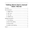
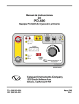
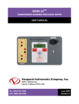
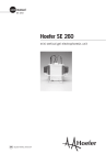
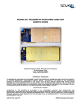
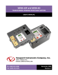
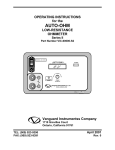
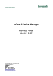
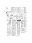
PCI-600
PRIMARY CURRENT INJECTION DEVICE
USER’S MANUAL
Vanguard Instruments Company, Inc.
1520 S. Hellman Ave.
Ontario, California 91761, USA
TEL: (909) 923-9390
FAX: (909) 923-9391
June 2013
Revision 2
PCI-600 USER’S MANUAL
REV 2
SAFETY SUMMARY
FOLLOW EXACT OPERATING PROCEDURES
Any deviation from the procedures described in this User’s Manual may create one or more
safety hazards, may damage the PCI-600, or cause errors in the test results. Vanguard
Instruments Company, Inc. assumes no liability for unsafe or improper use of the PCI-600.
All safety precautions provided in this manual must be observed during all phases of testing
including test preparation, test lead connection, actual testing, and test lead disconnection.
SAFETY WARNINGS AND CAUTIONS
Only trained operators shall use this device. All circuits under test shall be off-line and fully
isolated.
DO NOT MODIFY TEST EQUIPMENT
To avoid the risk of introducing additional or unknown hazards, do not install substitute parts or
perform any unauthorized modification to any PCI-600 test unit. To ensure that all designed
safety features are maintained, it is highly recommended that repairs be performed only by
Vanguard Instruments Company factory personnel or by an authorized repair service provider.
Unauthorized modifications can cause safety hazards and will void the manufacturer’s
warranty.
i
REV 2
PCI-600 USER’S MANUAL
TABLE OF CONTENTS
CONVENTIONS USED IN THIS DOCUMENT ..................................................................................... 1
1.0 INTRODUCTION .................................................................................................................... 2
1.1 General Description and Features ................................................................................... 2
1.2 PCI-600 Technical Specifications...................................................................................... 3
1.3 Controls and Indicators .................................................................................................... 4
2.0 OPERATING PROCEDURES ................................................................................................... 6
2.1 Functional Description ..................................................................................................... 6
2.1.1. AC Current Source .................................................................................................... 6
2.1.2. Current Output Control ............................................................................................ 6
2.1.3. Timer Stop Input and Control ................................................................................... 7
2.1.4. External Current Input .............................................................................................. 8
2.1.5. LCD Contrast Control ................................................................................................ 8
2.2 Performing Tests .............................................................................................................. 9
2.2.1. Testing the Open Time Delay of a Protection Relay ........................................................ 9
2.2.2. Measuring Current Transformer Primary and Secondary Currents .............................. 11
LIST OF TABLES
Table 1. PCI-600 Technical Specifications ....................................................................................... 3
Table 2. Functional Descriptions of PCI-600 Controls and Indicators ............................................ 5
Table 3. Current Output vs. Time.................................................................................................... 6
LIST OF FIGURES
Figure 1. PCI-600 Controls and Indicators ...................................................................................... 4
ii
PCI-600 USER’S MANUAL
REV 2
CONVENTIONS USED IN THIS DOCUMENT
This document uses the following conventions:
•
A key, switch, input, or knob on the PCI-600 is indicated as [KEY], [SWITCH], [INPUT],
[KNOB].
•
Menu options are referenced as (MENU OPTION).
•
PCI-600 LCD screen output is shown as:
1. OPTION
2. OPTION
3. OPTION
4. OPTION
•
1
2
3
4
Warning messages are indicated as:
Warning message
WARNING
•
Important notes are indicated as:
Note details
NOTE
1
REV 2
PCI-600 USER’S MANUAL
1.0
INTRODUCTION
1.1
General Description and Features
The PCI-600 is a programmable AC high-current source designed specifically for utilitysubstation applications. This device is well suited for primary injection testing of protective
relays. This versatile device can also be used for testing thermal, magnetic, and solid-state
motor-protection relays and molded-case circuit-breakers, as well as any application that
requires a high-current source.
Built-in Timer
The PCI-600’s built-in timer can test the time-delay characteristics of protection relays and
molded-case circuit-breakers. Once the test is initiated, the current source and the timer are
automatically turned on at the next zero-crossing point of the AC. The timer stops when the
PCI-600 input detects a change in the dry contact or voltage input, or detects the removal of
the test current. The test results are then displayed in milli-seconds and fractions of a cycle(s)
on the unit’s back-lit LCD screen (20 characters by 4 lines).
Current Source
Test currents, ranging from 10 to 600 amperes, can be set by using the rotary dial knob on the
control panel. The test current is then measured, and the results are displayed on the LCD
screen. When the PCI-600 is used as a current source, the current-on time (duration of current
flow) is displayed on the LCD screen.
External Current Input
The PCI-600 also has an external-current input (0 – 10 A). Both the internal current source
amplitude and the external current source measurement readings can be viewed at the same
time.
2
PCI-600 USER’S MANUAL
1.2
REV 2
PCI-600 Technical Specifications
Table 1. PCI-600 Technical Specifications
TYPE
100 - 600 Amp current source
PHYSICAL SPECIFICATIONS Dimensions: 17”W x 12.5”H x 10.5”D (42.6 cm x 32.0 cm x 27.0 cm);
Weight: 46 lbs (21 kg)
INPUT POWER 100 – 120 Vac or 200 – 240 Vac (factory pre-set), 50/60 Hz
INTERNAL METER RANGE
100 mA – 1000 A; Accuracy: 1% of reading ±20 mA
MEASUREMENT METHOD Isolated CT
EXTERNAL METER RANGE
10 mA – 10 A; Accuracy: 1% of reading, ±2mA
MEASUREMENT METHOD Isolated CT
TIMER READING RANGE
1ms – 2 hours; Accuracy: 0.1% of reading ±1ms
TIMER STOP INPUTS Voltage input (24V – 300V, DC or peak AC), dry contact input, or removal
of primary current
DISPLAY
COMPUTER INTERFACE
Back-lit LCD Screen (20 characters by 4 lines); viewable in bright sunlight
and low-light levels
RS-232C port for factory calibration and diagnostics
SAFETY Designed to meet IEC61010 (1995), UL61010A-1, CSA-C22.2 standards
ENVIRONMENT
CABLES
Operating: -10˚C to 50˚ C (15˚F to +122˚ F); Storage: -30˚ C to 70˚ C (22˚F to +158˚ F)
10-foot #1/0 AWG test leads, power cord, ground cable
OPTIONS Transportation case
WARRANTY
One year on parts and labor
The above specifications are valid at nominal operating voltage and at a
temperature of 25°C (77°F). Specifications may change without prior notice.
NOTE
3
REV 2
PCI-600 USER’S MANUAL
1.3
Controls and Indicators
The PCI-600’s controls and indicators are shown in Figure 1. A leader line with an index number
points to each control and indicator, which is cross-referenced to a functional description in
Table 2. The table describes the function of each item on the control panel. The purpose of the
controls and indicators may seem obvious, but users should become familiar with them before
using the PCI-600. Accidental misuse of the controls will usually cause no serious harm. Users
should also be familiar with the safety summary found on the front page of this User’s Manual.
Figure 1. PCI-600 Controls and Indicators
4
PCI-600 USER’S MANUAL
REV 2
Table 2. Functional Descriptions of PCI-600 Controls and Indicators
Item
Number
Panel Markings
Functional Description
1
Current lead connectors
2
Back-lit LCD screen (20 characters by 4 lines), viewable in bright sunlight and
low-light levels.
3
DRY CONTACT
WET CONTACT
CURRENT
4
TIMER STOP
5
EXT CURRENT
6
Timer and current source stop input selection with LED indicator. Stop input
mode is selected by using the arrow keys.
Timer "STOP" input connectors
External current input connectors
Input power connector
7
Circuit Breaker/Power Switch
8
GROUND
PCI-600 ground stud. Connect ground stud to substation ground using provided
cable.
9
CURRENT
CONTROL
10
RS-232C
11
HIGH
CURRENT
PRESENT
RS-232C port for factory calibration, diagnostics, and firmware updates
High current presence indicator LED
The up and down arrows are used to control the current source output and
timer. Three modes are available:
ON+TMR : Turns on current source and timer
OFF: Turns off current source and timer
MONT: Turns on current source momentarily
12
13
Current control knob
CONTRAST
LCD screen contrast control
5
REV 2
PCI-600 USER’S MANUAL
2.0
OPERATING PROCEDURES
2.1
Functional Description
2.1.1. AC Current Source
AC test currents from 10A to 600A are set by turning the
[CURRENT CONTROL] knob on the front panel. The test
current is measured and displayed on the LCD screen. The PCI600 output current ratings are shown in Table 3 below.
Table 3. Current Output vs. Time
Output @ 120 Vac
Output @ 240 Vac
Time
5.6 Vac @ 100 A
9.5 Vac @ 100 A
1 hour
5.3 Vac @ 200 A
9.4 Vac @ 200 A
5 minutes
4.9 Vac @ 300 A
9.0 Vac @ 300 A
2 minutes
4.6 Vac @ 400 A
8.2 Vac @ 400 A
1 minute
4.2 Vac @ 500 A
7.5 Vac @ 500 A
30 seconds
3.9 Vac @ 600 A
7.0 Vac @ 600 A
20 seconds
2.1.2. Current Output Control
The PCI-600 current source output is controlled by the [↑] and
[↓] keys. Three control modes are available:
ON + TMR This mode turns on the PCI-600's current source
and timer. This initiates a test and is stopped by
using the "Timer Stop" inputs. The test results will
be displayed on the LCD. The test can be
terminated by pressing the [↓] key. The PCI-600's
built-in time/cycle counter is used to time events in
milliseconds and cycles. The elapsed time is
displayed on the LCD along with the test current
after a test is completed.
6
OFF
In this mode both the current source output and
timer are off.
MONT.
This mode turns on the current source
momentarily. To turn on the current source, press
and hold the [↓] key. The PCI-600 current output
can now be set by turning the [CURRENT
CONTROL] knob. Release the [↓] key to turn off
the current source.
PCI-600 USER’S MANUAL
REV 2
2.1.3. Timer Stop Input and Control
After a test is started, the PCI-600 timer can be stopped and the
current source turned off using one of three options listed
below. Press the [→] key next to the option LED indicators to
select the mode.
DRY CONTACT
In "DRY CONTACT" mode, the PCI-600 will
output a DC voltage to the "TIMER STOP"
terminals to sense the state of dry contacts. A
change in this dry contact state will stop the
timer and turn off the current source. This
mode requires an external input to the PCI600. External timer stop input signals are
sensed through the "TIMER STOP" connectors.
WET CONTACT
In "WET CONTACT" mode, the PCI-600 will
sense an AC or DC voltage applied to the
"TIMER STOP" connectors. The "OFF" state is
any voltage from 0 to 10 V ac/dc. The "ON"
state is any voltage from 24 to 300 V ac/dc. A
change in the "Voltage" state will stop the
timer and turn off the current source. This
mode requires an external input to the PCI600. External timer stop input signals are
sensed through the "TIMER STOP" connectors.
CURRENT
In "CURRENT" mode, an interruption of the
PCI-600 current source output (CB contact
opened) will stop the timer and turn off the
current source.
7
REV 2
PCI-600 USER’S MANUAL
2.1.4. External Current Input
The PCI-600's “EXT CURRENT” input is a 10 ampere AC current
meter. This built-in ampere meter allows the user to monitor an
AC current. This current input is isolated. A typical application
for this feature is to measure a Current Transformer (CT)
current ratio. The user can set the PCI-600 to output a current
through the CT primary input. The CT secondary output is
measured with the PCI-600 “EXT CURRENT” input. Both the PCI600 output current and the CT secondary current are displayed
on the LCD allowing the user to easily calculate the CT current
ratio. The External Current’s polarity with respect to the PCI600 drive current is indicated on the LCD by a “+” sign (in phase)
or a “-” sign (out of phase). Proper phasing is indicated when
the same colored PCI connectors are connected to
corresponding terminals on the CT as shown below:
2.1.5. LCD Contrast Control
To change the contrast level on the PCI-600's LCD screen, press
and hold the contrast [→] key next to the LCD screen. Release
the contrast [→] key when the desired contrast level has been
reached.
8
PCI-600 USER’S MANUAL
2.2
REV 2
Performing Tests
2.2.1. Testing the Open Time Delay of a Protection Relay
Follow the steps below to test the Open Time Delay of a protection relay:
a. Make cable connections per the illustration below:
b. Turn the [CURRENT CONTROL] knob counter-clockwise to the zero position.
c. Turn on the power switch. After the initial informational screens, the following screen
will be displayed:
0mS
0.0CY
Ext I: +0.000 A
Drv I:
0.00 A
9
REV 2
PCI-600 USER’S MANUAL
d. From the "Timer Stop" section on the control panel, press the [→] key until "DRY
CONTACT" is selected as shown below:
e. Press and hold the [↓] key to momentarily turn on the current source:
f. Turn the [CONTROL KNOB] clockwise to set the desired current. The screen will be
updated as shown below:
0mS
0.0CY
Ext I: -0.000 A
Drv I: 20.00 A
g. Release the [↓] key.
h. Press the [↑] key to select "ON + TMR" mode and start the test:
i.
The PCI-600 will inject the preset current into the bus and turn on the timer. The LCD
will be updated as shown below:
986mS
59.2CY
Ext I: +0.000 A
Drv I: 20.00 A
j.
10
The timer will stop and the current source will turn off when the PCI-600 "TIMER STOP"
input detects a change in the relay dry contact, or if the operator presses the [↓] key
to select the "OFF" mode.
PCI-600 USER’S MANUAL
REV 2
2.2.2. Measuring Current Transformer Primary and Secondary Currents
Follow the steps below to measure current transformer primary and secondary currents:
a. Make cable connections per the illustration below:
b. Turn the [CURRENT CONTROL] knob counter-clockwise to the zero position.
c. Turn on the power switch. The following screen will be displayed:
0mS
0.0CY
Ext I: +0.000 A
Drv I:
0.00 A
d. Press and hold the [↓] key to momentarily turn on the current source:
11
REV 2
PCI-600 USER’S MANUAL
e. Turn the [CURRENT CONTROL] knob clockwise to set the desired current. The
screen will be updated as shown below:
0mS
0.0CY
Ext I: -0.000 A
Drv I: 20.28 A
f. Release the [↓] key when the desired current is displayed on the screen.
g. Press the [↑] key to select "ON + TMR" mode and start the test:
h. The CT primary and secondary currents will be displayed as well as the polarity as shown
below:
986mS
59.2CY
Ext I: -1.004 A
Drv I: 20.28 A
The External current polarity is shown either as in-phase (“+” sign) or out of
phase (“-” sign) with respect to the PCI-600's drive current.
NOTE
i.
12
Turn off the current source by pressing the [↓] key.
1520 S. Hellman Ave • Ontario, CA 91761 • USA
Phone: 909-923-9390 • Fax: 909-923-9391
www.vanguard-instruments.com
Copyright © 2013 by Vanguard Instruments Company, Inc.
PCI-600 User’s Manual • Revision 2 • June 28, 2013 • TA