1
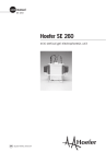
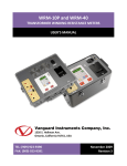
WRM-10TM
TRANSFORMER WINDING RESISTANCE METER
USER’S MANUAL
Vanguard Instruments Company, Inc.
1520 S. Hellman Ave.
Ontario, California 91761, USA
TEL: (909) 923-9390
FAX: (909) 923-9391
June 2009
Revision 2
WRM-10 USER’S MANUAL
REV 2
SAFETY SUMMARY
FOLLOW EXACT OPERATING PROCEDURES
Any deviation from the procedures described in this User’s Manual may create one or more
safety hazards, may damage the WRM-10, damage the test transformer, or cause errors in the
test results. Vanguard Instruments Company, Inc. assumes no liability for unsafe or improper
use of the WRM-10.
All safety precautions provided in this manual must be observed during all phases of testing
including test preparation, test lead connection, actual testing, and test lead disconnection.
SAFETY WARNING AND CAUTIONS
The WRM-10 shall be used only by trained operators. All transformers under test shall be offline and fully isolated.
DO NOT MODIFY TEST EQUIPMENT
To avoid the risk of introducing additional or unknown hazards, do not install substitute parts or
perform any unauthorized modification to any WRM-10 test unit. To ensure that all designed
safety features are maintained, it is highly recommended that repairs be performed only by
Vanguard Instruments Company factory personnel or by an authorized repair service provider.
Unauthorized modifications can cause safety hazards and will void the manufacturer’s
warranty.
WARNING
Do not remove test leads during a test. Failure to heed this warning can result in lethal
electrical shock to personnel and damage to the equipment.
i
REV 2
WRM-10 USER’S MANUAL
TABLE OF CONTENTS
CONVENTIONS USED IN THIS DOCUMENT ..................................................................................... 1
1.0 INTRODUCTION .................................................................................................................... 2
1.1 General Description and Features ................................................................................... 2
1.3 Technical Specifications ................................................................................................... 3
1.4 WRM-10 Controls and Indicators .................................................................................... 4
2.0 PRE-TEST SETUP ................................................................................................................... 6
2.1 Operating Voltages .......................................................................................................... 6
3.0 OPERATING PROCEDURES ................................................................................................... 9
3.1 WRM-10 Cable Connections ............................................................................................ 9
3.2 General Procedures ....................................................................................................... 11
3.3 Performing Transformer Tests ....................................................................................... 12
3.3.1. Performing a Single Resistance Test ...................................................................... 12
3.3.2. Performing a Voltage Regulator Test ..................................................................... 14
3.4 User Diagnostic Mode .................................................................................................... 16
LIST OF FIGURES
Figure 1. WRM-10 Controls and Indicators .................................................................................... 4
Figure 2. 100 – 120 Vac Jumper Settings ........................................................................................ 6
Figure 3. 200 – 240 Vac Jumper Settings ........................................................................................ 6
Figure 4. Relay Location .................................................................................................................. 7
Figure 5. Typical WRM-10 Connections Diagram #1 ...................................................................... 9
Figure 6. Typical WRM-10 Connections Diagram #2 .................................................................... 10
Figure 7. Typical Dual Winding Connections Diagram .................................................................. 10
LIST OF TABLES
Table 1. WRM-10 Technical Specifications ..................................................................................... 3
Table 2. Functional Descriptions of WRM-10 Controls and Indicators .......................................... 5
Table 3. Voltage Selection Jumper Settings .................................................................................... 6
ii
WRM-10 USER’S MANUAL
REV 2
CONVENTIONS USED IN THIS DOCUMENT
This document uses the following conventions:
•
The WRM-10’s control knob is referenced as [CONTROL KNOB]
•
Menu names are referenced as “MENU NAME”
•
WRM-10 LCD screen output is shown as:
MAIN MENU
<RUN TEST>
•
Warning messages are indicated as:
Warning message
WARNING
•
Important notes are indicated as:
Note details
NOTE
1
REV 2
WRM-10 USER’S MANUAL
1.0
INTRODUCTION
1.1
General Description and Features
The WRM-10 is designed to accurately measure the winding resistance of highly inductive
power transformers. The unit’s dual resistance-reading input channels can measure two
winding resistances simultaneously. Four-wire (Kelvin) connections provide high accuracy
voltage reading and require no lead compensation. The WRM-10 provides stable resistance
readings of very large transformers by utilizing a 36 Vdc power supply capable of outputting up
to 10 Amperes. The resistance reading of a 100MVA transformer can be achieved in 5 minutes
or less. The unit’s power supply is cooled by heavy-duty fans designed for continuous
operation.
Since the WRM-10 can accurately measure resistances ranging from 1 micro-ohm to 2,000
ohms, it can also be used to measure EHV circuit-breaker contact resistance, motor winding
resistance, or any low resistance. In addition to measuring the resistance value, the WRM-10
also checks the “make-before-break” tap-switching sequences of voltage regulators and load
tap changers.
The WRM-10 is furnished with three 50-foot test cables, a ground cable, a power cord, and a
cable carrying bag. Each test cable lead is terminated with a quick-disconnect test clip.
1.2
Functional Description
The WRM-10’s operation is based on the electrical relationship described by Ohm’s law: R=V/I,
where I is a known current and V is the DC voltage measured across the unknown resistance.
The value of the unknown resistance is calculated by dividing the measured voltage by the
current which is calculated by the microprocessor. Calculated resistance readings are then
displayed on the unit’s back-lit LCD screen.
A special current source allows the WRM-10 to output up to 10 Amperes of test current. The
test current is automatically adjusted depending on the load resistance. For added safety, the
current source circuit is thermally protected. Also, a built-in discharge circuit automatically
discharges the stored energy in the transformer at the end of each test.
2
WRM-10 USER’S MANUAL
1.3
REV 2
Technical Specifications
Table 1. WRM-10 Technical Specifications
TYPE
Portable transformer winding resistance meter
PHYSICAL SPECIFICATIONS 16.8”W x 12.6”H x 10.6”D (42.6 cm x 32.0 cm x 27 cm); Weight: 27 lbs
(12.2 kg)
INPUT POWER 100 – 120 Vac or 200-240 Vac (factory pre-set), 50/60 Hz
RESISTANCE READING 1 micro-ohm – 2,000 ohms
RANGE
ACCURACY
1 – 19,999 micro-ohms: ±0.5% reading, ±1 count
20 – 999 milli-ohms: ±1% reading, ±1 count;
1 – 2,000 ohms: ±1.5% reading, ±1 count
TEST VOLTAGE 36 Vdc max
TEST CURRENT RANGE Auto range, 10 Amperes max
DISPLAY
CONTROL
COMPUTER INTERFACE
Back-lit LCD Screen (16 characters by 2 lines); viewable in bright sunlight
and low-light levels
Single “turn-and-push” knob
RS-232C port (19,200 baud) used for factory calibration and diagnostics
SAFETY Designed to meet IEC61010 (1995), UL61010A-1, CSA-C22.2 standards
ENVIRONMENT
CABLES
Operating: -10˚C to 50˚ C (15˚F to +122˚ F); Storage: -30˚ C to 70˚ C (22˚F to +158˚ F)
Three 50-foot test cables, ground cable, power cord and cable bag
OPTIONS Transportation case
WARRANTY
One year on parts and labor
The above specifications are valid at nominal operating voltage and at a
temperature of 25°C (77°F). Specifications may change without prior notice.
NOTE
3
REV 2
1.4
WRM-10 USER’S MANUAL
WRM-10 Controls and Indicators
The WRM-10’s controls and indicators are shown in Figure 1 below. A leader line with an index
number points to each control and indicator, which is cross-referenced to a functional
description in Table 2. The table describes the function of each item on the control panel. The
purpose of the controls and indicators may seem obvious, but users should become familiar
with them before using the WRM-10. Accidental misuse of the controls will usually cause no
serious harm. Users should also be familiar with the safety summary found on the front page of
this User’s Manual.
Figure 1. WRM-10 Controls and Indicators
4
WRM-10 USER’S MANUAL
REV 2
Table 2. Functional Descriptions of WRM-10 Controls and Indicators
Item
Number
Panel Markings
1
V1
Voltage sensing input channel #1. Female connector jacks used for connecting
voltage-sensing test leads.
2
I
Current output. Female connector jacks used for connecting current test leads.
3
None
Back-lit LCD screen (16 characters by 2 lines); viewable in bright sunlight and
low-light levels.
4
GROUND
Safety ground terminal. 5/16-18 threaded stud with hand-turned wing nut. This
must be connected to the station ground before connecting any WRM-10 test
leads to the transformer.
5
100-120 Vac. 2A,
50-60 Hz
Fuse: 250 Vac, 3A
Slow-Blow
Functional Description
Input power connector with third-wire safety ground. On/Off rocker toggle switch
with built-in fuse protection.
9-pin RS-232C interface port; female DB type. Data rate is set to 19,200 baud,
1 start bit, 2 stop bits, 8 data bits and no parity bit.
Pin
Signal
6
RS-232C
2
RX
3
TX
5
Signal Ground
7
DISCHARGE
Red LED indicator light. This warning indicator is lit when the WRM-10 is
discharging the stored energy in the transformer. Do NOT disconnect the test
leads when this light is on. Failure to heed this warning can result in
shock and/or fatal injury to personnel.
8
CHANGE
“PUSH” TO
SELECT
Single turn-and-press control knob used to operate the WRM-10. You can scroll
through different menu options by turning this knob, and you can select a
function by pressing the knob.
9
HIGH VOLTAGE
PRESENT
10
V2
Red LED indicator light. This warning light is illuminated when there is a
possibility of high voltage across the test leads. Do NOT disconnect the test
leads when this light is on. Failure to heed this warning can result in
shock and/or fatal injury to personnel.
Voltage input sensing channel #2. Female connector jacks used for connecting
voltage-sensing test leads.
5
REV 2
WRM-10 USER’S MANUAL
2.0
PRE-TEST SETUP
2.1
Operating Voltages
The WRM-10’s operating voltage is preset at the factory and is selectable between 100-120
Vac, 50/60 Hz or 200-240 Vac, 50/60 Hz. The voltage is set by placing jumper(s) on the power
terminal block as listed in Table 3 and illustrated in Figure 2 and Figure 3. The relay must also be
changed if the voltage settings are changed. Please see Figure 4 for the location of the relay.
Table 3. Voltage Selection Jumper Settings
Voltage
Selection
Terminal Block Jumpers
Relay
Part Number
100 – 120 Vac
Brown to Blue and Yellow to Green
HE2aN-Q-AC120V
200 – 240 Vac
Blue to Yellow
HE2aN-Q-AC-240V
Figure 2. 100 – 120 Vac Jumper Settings
Figure 3. 200 – 240 Vac Jumper Settings
6
WRM-10 USER’S MANUAL
REV 2
Figure 4. Relay Location
7
REV 2
2.2
WRM-10 USER’S MANUAL
LCD Screen Contrast Control
To adjust the LCD screen’s contrast:
a. Start from the “MAIN MENU”:
MAIN MENU
<RUN TEST>
Turn the [CONTROL KNOB] till the following screen is displayed:
MAIN MENU
<ADJ CONTRAST>
Press the [CONTROL KNOB].
b. The following screen will be displayed:
ADJ CONTRAST
“PUSH” = DONE
Turn the [CONTROL KNOB] clockwise to increase the contrast (darken the screen).
Turn the [CONTROL KNOB] counter-clockwise to decrease the contrast (lighten the
screen).
Press the [CONTROL KNOB] when you are done adjusting the contrast level. You will
be returned to the “MAIN MENU”.
8
WRM-10 USER’S MANUAL
3.0
OPERATING PROCEDURES
3.1
WRM-10 Cable Connections
REV 2
Typical WRM-10 connections diagrams are shown in Figure 5 and Figure 6. A typical dual
winding connections diagram is shown in Figure 7.
WARNING
Do not touch or disconnect any test lead that is connected to a transformer
terminal while high current is being conducted during a test. Failure to heed this
warning can result in lethal electric shock to personnel and/or damage to the
equipment.
Figure 5. Typical WRM-10 Connections Diagram #1
WARNING
Disconnect the test clips from the transformer bushing only after the WRM-10
has completely discharged the transformer. Always disconnect the test clips
slowly from the transformer bushing to prevent an accidental flash-over.
9
REV 2
WRM-10 USER’S MANUAL
Figure 6. Typical WRM-10 Connections Diagram #2
NOTE
The above figure illustrates the simultaneous testing of both the high and low
windings on a single-phase transformer. When measuring two channels, the above
cable connection is recommended since it will speed up the testing process.
Figure 7. Typical Dual Winding Connections Diagram
10
WRM-10 USER’S MANUAL
3.2
REV 2
General Procedures
The main steps for using the WRM-10 are outlined below:
a. Ground the WRM-10 to the substation ground.
WARNING
Always connect the WRM-10 to the substation ground before connecting
any test lead to any transformer bushing. Failure to follow this procedure
may damage the WRM-10.
b. Plug the WRM-10 power cable into a power outlet.
c. Insert current-cable plugs and voltage-sensing cable plugs into the corresponding
control panel jacks.
d. Attach the test cable clamps to the transformer terminal for the winding that is to be
measured.
e. Turn on the WRM-10 by pressing [I] on the power rocker switch.
f. The unit will self-calibrate, and then you will be presented with the “MAIN MENU” as
shown below:
MAIN MENU
<RUN TEST>
11
REV 2
3.3
WRM-10 USER’S MANUAL
Performing Transformer Tests
3.3.1. Performing a Single Resistance Test
a. Start from the “MAIN MENU”:
MAIN MENU
<RUN TEST>
Press the [CONTROL KNOB].
b. The following screen will be displayed:
RUN TEST
<V1 & V2>
Turn the [CONTROL KNOB] till the following screen is displayed:
RUN TEST
<V1 ONLY>
Press the [CONTROL KNOB].
c. The following screen will be displayed:
FLASH-OVER IF
CABLES REMOVED!
Press the [CONTROL KNOB].
d. The following screen will be displayed:
“PRESS” TO START
“TURN” TO ABORT
Press the [CONTROL KNOB] to start the test. You can abort the test by turning the
[CONTROL KNOB].
e. The following screen will be displayed:
*XFMR CHARGING
The above screen will continue to display while the WRM-10 is performing the test (the
lightning bolts will be flashing). When the WRM-10 has determined that the resistance
readings are stable, the test results will be displayed as shown:
R1 = 10.0 mΩ
R2 = 10.5 mΩ
12
WRM-10 USER’S MANUAL
REV 2
The WRM-10 will continue to apply the test voltage on the transformer’s windings and
update the resistance values on the LCD screen. Press the [CONTROL KNOB] to stop
the test.
f. The WRM-10 will automatically discharge the transformer and display the following
screen during the discharging process:
DISCHARGE XFMR!
PLEASE WAIT...
After the transformer is discharged, the test results will be displayed on the screen as
shown:
R1 = 10.0 mΩ
R2 = 10.5 mΩ
Press the [CONTROL KNOB]. You will be returned to the “MAIN MENU”.
13
REV 2
WRM-10 USER’S MANUAL
3.3.2. Performing a Voltage Regulator Test
The Voltage Regulator Test verifies that a regulating switch in a primary voltage tap regulator
changes contacts through its selection range without a break in the circuit. This test is
important because in actual use, any break in the current in a regulating tap switch generates
large reactive voltage spikes that are hazardous and may exceed the switch’s voltage ratings,
thus causing irreparable damage. By connecting the WRM-10’s continuity test input across the
switching input and running the regulator switch through all the contacts in its range, any break
in continuity caused by faulty tap switching can be detected.
To perform a voltage regulator test:
a. Start from the “MAIN MENU”:
MAIN MENU
<RUN TEST>
Press the [CONTROL KNOB].
b. The following screen will be displayed:
RUN TEST
<V1 & V2>
Turn the [CONTROL KNOB] till the following screen is displayed:
RUN TEST
<VTG REG>
Press the [CONTROL KNOB].
c. The following screen will be displayed:
FLASH-OVER IF
CABLES REMOVED!
Press the [CONTROL KNOB].
d. The following screen will be displayed:
VTG REG TEST
“PUSH” TO START
Press the [CONTROL KNOB] to start the test.
14
WRM-10 USER’S MANUAL
REV 2
e. The following screen will be displayed while the test is being performed:
*XFMR CHARGING*
After the transformer has been charged, the following screen will be displayed:
V REG. TEST
RUN TAPS NOW
Run the voltage regulator tap switch.
f. If no transient is detected as the taps are switching:
1. The screen display will not change
2. Turn or press the [CONTROL KNOB] to end the test. The following screen will
be displayed:
NO TRANSIENT
DETECTED
If a switch break is detected:
1. The following message will be displayed:
TRANSIENT
DETECTED
2. Turn or press the [CONTROL KNOB] to end the test.
15
REV 2
3.4
WRM-10 USER’S MANUAL
User Diagnostic Mode
The user diagnostic mode can be used to monitor the V1 and V2 voltages and the test current
on the WRM-10’s LCD screen. To use the WRM-10 in user diagnostic mode:
a. Connect the WRM-10 to the test transformer, and then start from the “MAIN MENU”:
MAIN MENU
<RUN TEST>
Turn the [CONTROL KNOB] till the following screen is displayed:
MAIN MENU
<USER DIAG>
Press the [CONTROL KNOB].
b. The following screen will be displayed:
RUN TEST
<V1 & V2>
Turn the [CONTROL KNOB] till the following screen is displayed:
FLASH-OVER IF
CABLES REMOVED!
Press the [CONTROL KNOB].
c. The following screen will be displayed:
“PRESS” TO START
“TURN” TO ABORT
Press the [CONTROL KNOB] to start the test.
d. The following screen will be displayed momentarily:
CALIBRATING
PLEASE WAIT...
The WRM-10 will then alternate between displaying the following screens:
V1 = 1.03V
I = 00.005A
V2 = 1.03V
I = 00.005A
e. Press or turn the [CONTROL KNOB] to end the test. You will be returned to the
“MAIN MENU”.
16
1520 S. Hellman Ave • Ontario, CA 91761 • USA
Phone: 909-923-9390 • Fax: 909-923-9391
www.vanguard-instruments.com
Copyright © 2009 by Vanguard Instruments Company, Inc.
WRM-10 User’s Manual • Revision 2.0 • June 5, 2009 • TA