1
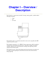
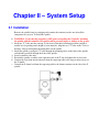
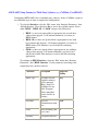
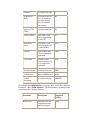
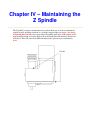
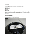
Z Spindle
Revision 1.2
Copyright ©1998-1999 Newing-Hall, Inc.
2019 Monroe Street
Toledo, Ohio, 43624
NH Part #2511013
Last Update July 2003
This manual is subject to change without notice.
Table Of Contents
Chapter 1 - Overview / Description
Chapter 2 - Setup
2.1 Installation
2.2 APEX-AMC Controller Configuration
2.3 APEX-HP3 Controller Configuration
2.4 APEX-JLS Machine Configuration/Toolbox Settings
2.5 APEX-JLS (Controller) Drivers
Chapter 3 – Z Spindle Usage
3.1 Spindle Anatomy
3.2 Spindle Adjustment
3.3 Standard Setup (Engraving Without A Nose)
3.4 Setting the Material Surface - AMC
3.5 Setting the Material Surface - HP3
3.6 Floating Head Setup
3.7 11/64" & 1/4" Standard Spindle
3.8 Collet Spindle
3.9 Diamond Insert
3.10 Setting the Material Surface, AMC, HPGL
3.11 Designing the Work File
3.12 Engraving the Work File
Chapter 4 - Maintaining the Z Spindle
Chapter I – Overview /
Description
The Z Spindle is a stepper-motor controlled 3-bearing, rotating spindle, available with the
following tool options:
•
•
•
11/64"
1/4"
1/4"Collet
The Z Spindle requires an externally mounted drive motor, and is compatible with NHIstandard rotary drive systems.
The Z Spindle is actuated by a 1.8°, NEMA-23 frame stepper motor, which is attached to
an internal lead screw/actuator nut. The motor is connected via cabling to the motion
controller, which drives the tool up and down according to the depths and positions
required by the motion program.
The Z Spindle also has a spring-loaded floating head feature that allows the spindle to be
used with a standard engraving nose that follows the contour of the material surface
during engraving.
Chapter II – System Setup
2.1 Installation
Remove the spindle from its packaging and examine the contents to make sure that all the
components are present. To install the spindle:
1. WARNING: Verify that the controller is OFF prior to installing the Z Spindle. Installing
the spindle with the controller ON could result in personal injury or damage to the system.
2. Insert two "T" bolts onto the carriage T-slot in one of the three horizontal positions (middle is
usually best, depending on the height of your material). Align the two "T" bolts on the T-slot so
that they will pass through the mounting holes on the spindle.
3. Install the spindle, passing the "T" bolts through the mounting holes on the back of the spindle,
such that they protrude through the front of the spindle.
4. Loosely attach two hex nuts.
5. Position the spindle assembly at the right-most end of the T-slot and tighten the two hex nuts.
6. Connect the 8-position motor connector from the engraving table to the stepper motor on top of
the Z spindle.
7. Connect the Z datum lead from the engraving table to the datum connector on the side of the Z
spindle.
2.2 APEX-AMC Controller Configuration
The next step is to setup the controller to utilize the Z Spindle.
AMC Setup is a DOS-based setup tool for AMC controllers. If you have an HPGL
controller, please consult the appropriate text later in this section. After installation, AMC
Setup is used to change various operating parameters.
APEX-AMC Setup Params (General)
1. Click [Start], and then select ‘Programs’ followed by ‘APEX-AMC’, and ‘AMC Setup’.
2. Select the ‘File’ menu, then ‘Open’ and cursor down to select the desired INI file. Press Enter to
open the INI file for editing.
3. To set the Z Travel, select the ‘Edit’ menu, then ‘Axis Parameters’, then ‘Miscellaneous Axis
Parameters’. Using the cursor keys, highlight the ‘Maximum Axis Limit’ field in the ‘Z Axis’
column. Enter the desired value, in inches or mm. A good value is 1.0 inches/sec. This value is
pre-set at the factory, and it is strongly suggested that the user does NOT change it.
4. Go on to the next section, based on the host software you will be using…
APEX-AMC Setup Params for APEX-JLS Software
JLS uses the default "GPS" protocol. As such, there is no need to configure a custom
protocol or setup software drivers:
1. To set the (Z) Up and Down Feed rate, select the ‘Edit’ menu, then ‘Axis
Parameters’, then ‘Miscellaneous Axis Parameters’. Using the cursor keys,
highlight the ‘Maximum Speed’ field in the ‘Z Axis’ column. Enter the desired
value, in steps per sec or in/mm per min. A good value is 30 inches per min. Note
that this is the MAXIMUM speed. The actual speed during engraving will vary,
and the base feed rate can be modified in the JLS Toolbox (see ‘APEX-JLS
Configuration’, below).
2. The (Z) Clearance, Depth, and Number of Passes are not configurable in the
controller, but are defined in the JLS Toolbox (see ‘APEX-JLS Configuration’,
below).
3. Select the ‘File’ menu, then ‘Exit’ to exit the Setup Software. The new
parameters are saved in the INI file (NOT in the AMC controller). Copy the
changed INI file to \APEX\PROG.
4. To update the controller, select ‘Load F/W’ on the AMC controller’s front panel
(also set the baud rate to 38400 – if necessary).
5. Click [Start], and then select ‘Programs’ followed by ‘APEX-AMC’, and the
appropriate FLASH icon (e.g. "Model 300 COM1"). Wait while the controller is
re-Flashed. The new parameters are now saved in the AMC controller.
Note: It will be necessary to establish the actual Z-axis up- and down-feed, clearance,
cutting depth, and passes in the JLS toolbox prior to engraving (see ‘APEX-JLS
Configuration’, below).
APEX-AMC Setup Params for Third-Party Software (e.g. CASMate, CorelDRAW)
Configuring APEX-AMC for use with third-party software, such as CASMate, requires a
few additional steps in order to complete the configuration:
1. To select the Interface, select the ‘Edit’ menu, then ‘Interface Parameters’, then
‘Default Interface’. Press the Space Bar to access the available options. Select
either ‘HPGL’, ‘HPGL 3D’ or ‘G&M’ and press the [Enter] key:
•
•
•
HPGL is a two-axis protocol that is appropriate for use with host
software that supports ‘2½-D’motion commands (see below) in
HPGL format.
HPGL 3D is a three-axis protocol that is appropriate for use with
host software that supports ‘3-D’motion commands (see below) in
HPGL format. This interface is used for full 3D contouring
applications.
G&M is a three-axis protocol that is appropriate for use with host
software that supports ‘3-D’motion commands (see below) in G
and M code format. This interface is used for full 3D contouring
applications.
To configure an HPGL Interface, select the ‘Edit’ menu, then ‘Interface
Parameters’, then ‘HPGL Interface’. Set the parameters according to the
requirements for your host software:
Parameter
Description
Suggested
Setting
Buffer Type
Describes how the
controller memory
will be managed.
‘Ring’ allows for
indefinite file size,
while ‘Program’
allows immediate
restarts for files in
memory.
Ring
Baud Rate
Speed of
communication with
host.
9600
Parity
Parity checking (odd,
even, none)
N
Data Bits
As required for host.
8
Stop Bits
As required for host.
1
ACK/NACK
Mode
As required for host.
(‘No’ for hardware
error flow control,
‘Yes’ for software
flow control)
No
Suppress CTS
Check
As required for host.
No
Tool Up Dwell
Delay with 2 ½ D
prior to motion with
the tool UP.
0.1
Tool Down
Dwell
Delay with 2 ½ D
prior to motion with
the tool DOWN.
0.25
Z Depth
Depth of cut with 2
½ D, as required for
application.
0.020
Z Clearance
Clearance above
material surface 2 ½
D, as required for
application.
0.10
Data Resolution
As required for host.
0.001
Symbol Units
Inches or Millimeters
Inches
Symbol
Resolution
As required for host.
0.000250
To configure the G&M Interface, select the ‘Edit’ menu, then ‘Interface
Parameters’, then ‘G&M Interface’. Set the parameters according to the
requirements for your host software:
Parameter
Description
Suggested
Setting
Buffer Type
Describes how the
controller memory
will be managed.
Ring
‘Ring’ allows for
indefinite file size,
while ‘Program’
allows immediate
restarts for files in
memory.
Baud Rate
Speed of
communication with
host.
9600
Parity
Parity checking (odd,
even, none)
N
Data Bits
As required for host.
8
Stop Bits
As required for host.
1
ACK/NACK
Mode
As required for host.
(‘No’ for hardware
error flow control,
‘Yes’ for software
flow control)
No
NAK Error Codes
As required for host.
Disabled
Suppress CTS
Check
As required for host.
No
Tool Up Dwell
Delay with 2 ½ D
prior to motion with
the tool UP.
0.1
Tool Down Dwell
Delay with 2 ½ D
prior to motion with
the tool DOWN.
0.25
Z Depth
Depth of cut with 2
½ D, as required for
application.
0.020
Z Clearance
Clearance above
material surface 2 ½
D, as required for
application.
0.10
Feed Rate Units
As required for host,
(in/mm per minute or
%)
%
Spindle Speed
Units
As required for host.
(Rpm or %)
%
Symbol Units
Inches or Millimeters
Inches
Symbol
Resolution
As required for host.
0.000250
To set the Height Control Mode, select the ‘Edit’ menu, then ‘Tool Parameters’,
then ‘System Tool Parameters’. Using the cursor keys, highlight the ‘Height Ctrl
Mode’ field. Press the Space Bar to access the available options. Select either
‘2½-D’ or ‘3-D’ and press the [Enter] key:
•
•
3-D causes the controller to interpret Z-axis tool commands in the
same way as x- and y-axis motion commands. This means that
during motion, the controller will obey position references coded
in the motion sequence for ALL axes (including Z), which allows
full simultaneous interpolation for contouring application. Using
this setting requires that the host software be configured for
generating the 3-axis motion commands.
2 ½-D causes the controller to interpret Z-axis tool commands as
"pen up" and "pen down". This means that during motion, the
controller will slow tool motion to a stop, then pause briefly,
retract the tool to its "clearance" height, then move to the start of
the next motion command, then pause briefly, and re-insert the tool
into the material. This allows the controller to be used with host
software that does not support full 3D motion.
If configuring for 2 ½-D, you must also configure the Tool Height Setting value.
Select the ‘Edit’ menu, then ‘Tool Parameters’, then ‘System Tool Parameters’.
Using the cursor keys, highlight the ‘Tool Height Setting’ field. Press the Space
Bar to select Yes or No, and then press the [Enter] key (default is No).
Select the ‘File’ menu, then ‘Exit’ to exit the Setup Software. The new
parameters are saved in the INI file (NOT in the AMC controller).
To update the controller, select ‘Load F/W’ on the AMC controller’s front panel
(also set the baud rate to 38400 – if necessary).
Click [Start], and then select ‘Programs’ followed by ‘APEX-AMC’, and the
appropriate FLASH icon (e.g. "Model 300 COM1"). Wait while the controller is
re-Flashed. The new parameters are now saved in the AMC controller.
Note: Be sure to check/set the desired Z-axis up- and down-feed, clearance,
cutting depth, and passes in the host software prior to engraving (see ‘APEX-JLS
Configuration’, below).
2.3 APEX-HP3 Controller Configuration
After installation, the next step is to setup the controller to utilize the Z Spindle. Machine
Parameters is a Windows95/NT-based setup tool for HP3 controller. If you have an AMC
controller, please consult the appropriate text earlier in this section. After installation,
Machine Parameters is used to change various operating parameters such as Auto Park
status, VST tolerance, or Spindle type.
1. Click [Start], and then select ‘Programs’ followed by ‘APEX Product Software’,
and Machine Parameters.
2. To set the (Z) Travel, select the Table Parameters located on the left pane. Scan
down the parameter list to locate ‘Z Stroke Size’. Enter the desired value, in
inches or mm. A good value is 1.0 inches/sec. This value is pre-set at the factory,
and it is strongly suggested that the user does NOT change it.
3. Related to the (Z) Travel, HPGL controllers also use a ‘Z Negative Stroke’ that
is the distance the tool is permitted to move beyond the machine origin. To set
this parameter, scan down through the parameter list to locate ‘Z Negative
Stroke’. Enter the desired value, in inches or mm. A typical value is 0.0
inches/sec, but this may vary depending on the position after DATUM. This value
is pre-set at the factory, and it is strongly suggested that the user does NOT
change it.
4. To set the (Z) Down Feed, select the Input/Output Parameters located on the left
pane. Scan down through the parameter list to locate ‘Tool Plunge Speed’. Enter
the desired value, in inches/sec or mm/sec. A good value is 0.5 inches/sec.
5. To set the (Z) Up Feed, select the Input/Output Parameters located on the left
pane. Scan down through the parameter list to locate ‘Tool Lift Speed’. Enter the
desired value, in inches/sec or mm/sec. A good value is 2.0 inches/sec.
6. To set the Clearance, select the Input/Output Parameters located on the left pane.
Scan down through the parameter list to locate ‘Tool Lift Height’. Enter the
desired value, in inches or mm. A good value is just enough for the tool to clear
the surface of the material and any fixturing or jigging.
7. To set the Depth, select the Input/Output Parameters located on the left pane.
Scan down through the parameter list to locate ‘Tool Cut Depth’. Enter the
desired value, in inches or mm. A good value is just enough for the tool to clear
the surface of the material and any fixturing or jigging.
8. Select the File menu, then ‘Update Machine Tool’. Answer ‘Yes’ to save the
changes to the HP3 controller AND to disk.
9. Exit Machine Parameters. The new parameters are saved in the HPGL controller.
Note: The Number of Passes is established during engrave-time, and is set from the HP3
controller’s main menu. To set the Number of Passes, scroll down the option list to display
‘Z_Delta’ and press [Enter]. Enter the ‘MP Depth Increment in inches or mm and press [Enter].
The controller will repetitively execute command sequences starting with ‘PU;’ and ending with
‘PD:’ until the desired total Depth is achieved.
Also Note: The above parameters may be overridden, or set temporarily from the HP3
controller’s main menu, or by the host software prior to engraving. Maximum travel and speed
defined in the controller cannot be exceeded by external means.
2.4 APEX-JLS Machine Configuration and Tool Box
Settings
In order to design a work file for use with the Z spindle to engrave without a nose, it is
first necessary to configure the JLS design software to output in 3D. To do this, the
proper machine setup file is required:
1.
2.
3.
4.
5.
Start APEX-JLS: DO NOT load a work file.
Click on the Options Menu.
Click on the Machine Configuration command.
Click on the appropriate machine driver (e.g. M300ZDAT).
Click on [OK] to complete the configuration.
See Chapter 16 in the APEX-JLS User’s Manual for further details.
Three-axis Machine Configuration (With a Nose)
The Z Spindle also can be configured to engrave with a nose in 2 ½-D mode, and also
with a diamond insert in 2 ½-D mode (see previous section). Follow the standard
procedures for creating work files in APEX-JLS. Then, configure the Tool Box for each
Cutting Spec / Tool combination:
Pneumatic Head:
This checkbox switches the Tool Box from the standard
three-axis parameters to two-axis parameters. This removes
items such as "Passes" and "Depth", and restores access to
the machine dwells – which are pertinent for engraving
with a nose.
Dwell Down
Dwell Down specifies the amount of time to pause (in
seconds) after the execution of a "tool down" operation.
This pause is enacted to allow the tool to cut down into the
material to reach the "down" position prior to starting
lateral motion.
Dwell Up
Dwell Up specifies the amount of time to pause (in
seconds) after the execution of a "tool up" operation. This
pause is enacted to allow the tool to retract out of the
engraving material prior to starting lateral motion.
Three-axis Machine Configuration (Without a Nose)
The Z Spindle can be configured to engrave without a nose in 3-D mode. Follow the
standard procedures for creating work files in APEX-JLS. Then, configure the Tool Box
for each Cutting Spec / Tool combination:
Pneumatic Head: This checkbox switches the Tool Box from the standard three-axis
parameters to two-axis parameters. The importance of this is discussed in the next
section.
Passes
The Passes parameter describes the number of times the work file will be
engraved in order to achieve the desired depth. Each pass penetrates the
engraving material in equal amounts until the desired depth is achieved
(see below). For example, to cut to a depth of 0.100 inches in 5 passes
means that each successive pass will penetrate 0.020 inches.
Depth
This Depth refers to the total depth of the cut. The depth may vary with
each application, and for each cutting spec in the work file.
Z Clearance
The Z Clearance is the desired distance between the point of the tool and
the material surface during tool-up motion (traverse).
Speed Down
Speed Down is the down feed rate for the Z-axis (not used in HPGL
mode). This should be sufficiently fast in order to minimize job time, but
slow enough to provide adequate time for the tool to cut down into the
material without stalling. Lateral motion does not begin until the tool is
fully inserted to its "Depth" position.
Speed Up
Speed Up is the up feed rate for the Z-axis (not used in HPGL mode). This
should be set to the maximum speed (100%) to minimize job time. Lateral
motion does not begin until the tool is fully retracted to its "Z Clearance"
position.
2.5 APEX-JLS (Controller) Drivers
APEX-JLS can output to the AMC controller using its (default) AMC driver, or to an
HPGL controller using an HPGL driver. The correct driver setup is necessary for
successful communications between the host PC and the controller.
AMC Driver
1.To setup the AMC controller, select the Setup command from the Execute menu.
2. Click the [Setup] button and verify the parameters:
Parameter
Setting
COMM
COMM 1 or COMM 2, as
desired
Baud Rate
115200
3. Click [OK].
4. Click on the [Set As Default Machine] button.
5. Click on the [Close] button to complete the process.
HP3 Driver
1. To setup the HP3 controller, select the Setup command from the Execute menu.
2. If necessary, create an HPGL driver:
a. Click on the [Add] button.
b. Enter a "group name", such as "HP2" or "HP3" and click [OK].
c. Click on the [Setup] button.
d. Set the parameters:
Parameter
Setting
COMM
COMM 1 or COMM 2, as
desired
Baud Rate
38400
Parity
Even
Data Bits
8
Stop Bits
1
Flow Ctrl
Hardware
Resolution
1/1000"
Accuracy
0.5
e. Enter any desired HPGL command codes that should precede EACH work file in the
Send Before edit window (usually none).
f. Enter any desired HPGL command codes that should follow after the completion of
EACH work file in the Send After edit window (usually none).
g. Click on [OK] to complete the definition.
3. Click on the [Set As Default Machine] button.
4. Click on the [Close] button to complete the process.
Note: The following Tool Box parameters ARE NOT SUPPORTED in HPGL mode:
•
•
•
•
•
•
•
Feed Rate
(Z) Speed Up
(Z) Speed Down
Spindle RPM
Finishing Cuts
Dwell Up
Dwell Down
These parameters must be set using Machine Parameters on the HPGL controller.
Chapter III – Z Spindle Usage
3.1 Spindle Anatomy
The following is an overview of the Z-Spindle’s basic construction:
3.2 Spindle Adjustment
Now that the spindle, controller and software are configured, it is necessary to make final
adjustments to the spindle prior to engraving. To adjust the spindle:
1. Turn the controller ON
2. Press [Drives On] followed by [Datum] to datum the system. The Z Spindle
should datum FIRST, followed by X and Y-axes. If the Z Spindle does not
datum - STOP! Contact NHI Customer Service for further instructions. The
spindle will not function properly without a functional Z datum sensor. (This may
be due to reverse connection of the Z datum connector.)
3. With the spindle carriage now positioned in the upper-left corner of the engraving
area, loosen the two hex (mounting) nuts and re-position the Z Spindle as desired
on the carriage T-slot.
4. Tighten the two hex nuts to complete the procedure.
5. Install an appropriate cutting tool (see later sections for details).
6. Install the rotary drive assembly (for details see the JLS manual).
7. Attach the drive belt between the spindle pulley and the rotary drive assembly.
8. Inspect the rotary drive assembly to ensure that the belt(s) will not contact wires
during engraving.
3.3 Standard Setup (Engraving Without A Nose)
Prior to engraving, it is necessary to establish the surface of the material. This should be
done each time the engraving material is changed.
3.4 Setting the Material Surface - AMC
APEX-AMC
To set the material surface:
1. Verify that the system is powered-up and datummed, with a tool in the spindle,
and the floating head locked.
2. Jog the tool over the engraving material.
3. Press [Digitize].
4. Press AND HOLD the [Z] key, and then jog the tool down until it just touches the
material surface (it is often helpful to place a piece of paper on the material
surface, moving it while jogging until it is pinned down by the point of the tool).
5. Press *[F2] to set the surface (the tool will retract).
6. Press [Esc] to exit the menu system.
3.5 Setting the Material Surface - HP3
APEX-HP3
To set the material surface:
1. Verify that the system is powered-up and datummed, with a tool in the spindle,
and the floating head locked.
2. Jog the tool over the engraving material.
3. Press [Digitize].
4. Press the [Z] key, and then jog the tool down until it just touches the material
surface (it is often helpful to place a piece of paper on the material surface,
moving it while jogging until it is pinned down by the point of the tool).
5. Press [Digitize] (again) to set the surface (the tool will retract).
Note: Regardless of the controller used, the material surface should be reset each time…
•
•
•
…the machine is datummed.
…the engraving material is changed.
…the cutting tool is changed.
3.6 Floating Head Setup
When engraving with a nose, the distance between the nose and the point of the cutting tool establishes
the actual engraving depth. However, it is still necessary to "set the surface" when using the floating
head – either with a rotating tool or the diamond spindle insert. This establishes a general (z-axis)
position for the controller to reference as "tool down".
3.7 11/64" & 1/4" Standard Spindle
1. Place a piece of scrap material on the engraving table beneath the spindle.
2. Loosen the setscrew on the front of the Z spindle stop plate. This unlocks the
floating head mechanism, allowing the tool to float.
3. Verify that the engraving nose assembly is installed on the bottom of the Z
Spindle, and set the micrometer sleeve so that the indicator points to zero.
4. While gripping the cutting tool shank, loosen the setscrew on the brass cutter head
with the supplied cutter head wrench and lightly pull UP on the shank. Withdraw
the cutting tool until it disappears inside the nose assembly. The point of the
cutting tool MUST NOT protrude beyond the engraving nose.
5. Tighten the setscrew on the brass cutter head.
6. Jog the Z Spindle DOWN until it touches the material surface, allowing for a
slight amount of over-shoot (approx. 1/8") to account for variations in the material
surface.
7. While gripping the cutting tool shank, loosen the setscrew in the brass cutter head.
8. Push the shaft lightly so that the tip of the cutting tool touches the engraving
material.
9. Tighten the setscrew in the brass cutter head.
10. Digitize the surface (see below).
3.8 Collet Spindle
1. Place a piece of scrap material on the engraving table beneath the spindle.
2. Loosen the setscrew on the front of the Z spindle stop plate. This unlocks the
floating head mechanism, allowing the tool to float.
3. Verify that the engraving nose assembly is installed on the bottom of the Z
Spindle, and set the micrometer sleeve so that the indicator points to zero.
4. Loosen the drawbar by turning the knurled knob at the top of the spindle pulley
anti-clockwise.
5. Slide the cutting tool shank up into the bore until it disappears inside the nose
assembly. The point of the cutting tool MUST NOT protrude beyond the
engraving nose.
6. Tighten the drawbar.
7. Jog the Z Spindle DOWN until it touches the material surface, allowing for a
slight amount of over-shoot (approx. 1/8") to account for variations in the material
surface.
8. While gripping the cutting tool shank, loosen the drawbar.
9. Push the shaft lightly so that the tip of the cutting tool touches the engraving
material.
10. Tighten the drawbar.
11. Digitize the surface (see below).
3.9 Diamond Insert
1. Place a piece of scrap material on the engraving table beneath the spindle.
2. Loosen the setscrew on the front of the Z spindle stop plate. This unlocks the
floating head mechanism, allowing the tool to float.
3. Verify that the diamond insert is present and the nose assembly is installed on the
bottom of the Z Spindle.
4. Jog the Z Spindle DOWN until it touches the material surface, allowing for a
slight amount of over-shoot (approx. 1/8") to account for variations in the material
surface.
5. Digitize the surface (see below).
3.10 Setting the Material Surface, AMC, HPGL
Digitize Surface – Floating Head
1. It is still necessary to "set the surface" when using the floating head – either with
a rotating tool or the diamond spindle insert. This will give a general (z-axis)
position for the controller to reference as "tool down".
2. On AMC, press [Digitize], *[F2], [Esc] to set the surface.
3. On HP3, press [Digitize], [Digitize] to set the surface.
4. Jog the Z Spindle UP to an appropriate height. The floating head is ready or
engraving in 2½ D mode with the diamond insert.
3.11 Designing the Work File
Users of JLS may consult Chapters 8 and 16 in the JLS User’s Manual for explanations
of the Toolbox and other settings in the following text. For details about other software,
please consult that software’s user manual(s). The following text assumes that the
design software is APEX-JLS.
In order to design a 3D work file for use with the Z spindle, it is first necessary to
configure the design software to output in 3D. To do this, the proper machine setup file
is required:
1.
2.
3.
4.
5.
Start APEX-JLS: DO NOT load a work file.
Click on the Options Menu.
Click on the Machine Configuration command.
Click on the appropriate machine driver (e.g. M300Z).
Click on [OK] to complete the configuration.
See Chapter 16 in the APEX-JLS User’s Manual for further details.
In order to design a 2-½ D work file for use with the Z spindle, it is first necessary to
configure the design software to output in 2-½ D. To do this, the proper machine setup
file is required:
1.
2.
3.
4.
5.
Start APEX-JLS: DO NOT load a work file.
Click on the Options Menu.
Click on the Machine Configuration command.
Click on the appropriate machine driver (e.g. MODEL300, M300D).
Click on [OK] to complete the configuration.
See Chapter 16 in the APEX-JLS User’s Manual for further details.
Users of design software other than APEX-JLS are referred to the software and controller
manuals for details and methods for configuring these parameters.
3.12 Engraving the Work File
The material surface must be defined prior to engraving a work file. If the material
surface has not been previously defined, you will be prompted by the controller to define
it. Refer to the previous sections "Setting the Material Surface" for details on this
procedure.
When engraving with a nose (2-1/2 D), the depth is controlled by the nose on the spindle
– rather than the motion program. Therefore, the depth must be set prior to engraving the
work file. In order to establish the cutting depth, it is necessary to setup the floating head
on the Z Spindle (see Quick Start) and zero the cutting tool. Thereafter, turn the
micrometer sleeve until the indicator reads the desired depth (in thousandths of an
inch).
To engrave the work file, simply select the "Machine" command from the Execute Menu
in APEX-JLS.
Chapter IV – Maintaining the
Z Spindle
The Z Spindle is largely a maintenance-free product. However, in order to maintain the
spindle in good operating condition, it is strongly suggested that you apply a few drops
of light machine-tool oil to the region where the spindle quill enters (and actuates in) the
main spindle housing, and on the guide rods in the floating head mechanism. Do this on a
daily basis. This will assure that sufficient lubrication is present to prevent untimely
wear.