1
4.3 Cautions
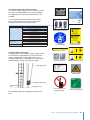
Prior to installation, ensure that:
• Building sections involved will be able to withstand the
service lift loads.
• All parts are available and fully functional.
• Travel zone is protected by fences at each platform.
• Walking way surfaces are dry and not slippery.
The customer must define the maximum allowable
wind speed ensuring safe installation.
During installation tasks, personnel shall:
• Wear at least the following PPE: fall arrest equipment
if falling height is higher than 2 m, hand gloves, helmet,
safety glasses, working gear.
• Use a hand winch attachable to the ladder when
elevating heavy weights.
• Use a cable clamp or grip when lowering traction and
safety wire ropes.
• Not work at different levels if tasks involve risk of falling
objects.
Installation shall be performed by AVANTI or trained
personnel by AVANTI. At the end of the workday security measures must be taken to put the service lift out of
service and make the ladder accessible.
4.4 Service lift installation
The WTG manufacturer shall provide 3D drawings to ensure that installation of lift on ladder is possible.
6. Mount fixing set for transport to prevent lift from moving during transport of tower section.
7. The tower sections shall be transported to the wind
farm.
8. After tower erection takes place, follow instructions
from chapter “4.5 Electrical connections on-site” onwards.
4.5 Electrical connections on site
Before making any connection, disconnect any
power supply to the service lift and the fence
interlock system; and verify with WTG responsible.
The electrical connection of the traction hoist must be
made in accordance with EN 60204-1.
The power supply must be protected by a fuse and
against indirect contacts according to local regulations.
Verify that the rated grid and motor voltages are identical.
Electrical system shall be properly insulated.
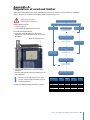
4.6 Travelling cable
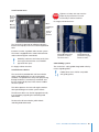
1.Install power supply socket over mid tower´s height
platform; and install a cable relief on the platform
fence.
Platform fence
4.4.1 After tower erection
The service lift is installed on to the ladder after tower
erection.
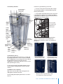
1. Mount safe zone plates, top limit plate and rest
platforms on ladder, according to installation drawing
ID00112.
2. Fit the nuts and bolts to the shackles, and lock with
cotter pins.
3. Mount traction and safety wire ropes (Ø8 mm) using
the shackles supplied for the top beam at the top of the
tower.
4. Follow instructions from chapter “4.5 Electrical connections on-site” onwards.
4.4.2 Before tower erection
Alternatively, the service lift can be installed on to the
ladder before tower erection. With the tower section lying
horizontally:
1. Mount safe zone plates, final limit activation plates and
rest platforms on ladder, according to installation drawing
ID00112.
2. Fit the nuts and bolts to the shackles, and lock with
cotter pins.
3. Mount traction and safety wire ropes (Ø8 mm) using
the shackles supplied for the top beam at the top of the
tower.
4. Attach coiled wire ropes to top beam by means of
cable strips to prevent them from moving during transport
of tower section.
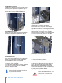
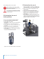
5. Position service lift on ladder at bottom platform, by
means of a crane and the lifting eyes, and according to
dimensions of installation drawing ID00112.
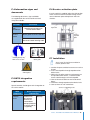
Support
Cable
Relief
Travelling
Cable
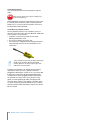
2.Feed travelling cable through the cable relief,
without plugging it to power supply socket!
3.Uncoil the cable to the bottom platform.
The travelling cable must be evenly uncoiled to prevent looping.
4.Plug travelling cable outlet directly to service lift (provisional connection).
5.Plug travelling cable inlet to power supply socket over
mid tower´s height.
User’s, Installation and Maintenance Manual 21