Download gasguard sensor user manual issue 3
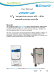
Transcript
SENSOR UNITS
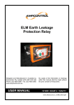
Designed and Manufactured in Australia by
Ampcontrol Pty Limited ACN 000 915 542
Phone: (02) 4956 5899 Fax: (02) 4956 5985
www.ampcontrol.com.au
USER MANUAL
No copies of the information or drawings
within this manual shall be made without
the prior consent of Ampcontrol.
E08975 ISSUE 3 26/05/04
Gasguard_Manual_Issue_3_E08975_260504.pdf
GASGUARD SENSOR USER MANUAL ISSUE 3
IMPORTANT WARNINGS AND ADVICE
Copyright Notice
No part of this publication may be
reproduced, transmitted or transcribed into
any language by any means without the
express written permission of Ampcontrol
Pty Ltd, 250 Macquarie Road Warners Bay,
NSW 2282, Australia.
1.
The sensors should not be stored in areas that
contain solvent vapours. Some of these vapours
are known to create false "high" zero points and
may even damage the sensor electrodes.
Similarly, the sensor should not be exposed to
high levels of solvent vapours while in
operation.
2.
This equipment has been designed to detect
hazardous gases and vapours and to give
warning before they reach dangerous
conditions. In order to ensure that the
equipment will warn of dangerous situations it is
essential that the instructions in this manual be
read, understood and followed. It is further
stressed that the effectiveness of the device
depends heavily on the user who is responsible
for its correct application, use and regular
maintenance.
3.
During start up, electrochemical sensors often
require loop currents in excess of 20mA. The
Ampcontrol toxic-gas sensors described herein
are limited to a maximum of 30mA. It is essential
that the circuit into which they are connected is
capable of delivering at least 30mA without
compromising either Intrinsic Safety (if
applicable) or the specifications of monitoring
equipment.
4.
Note the maximum gas to be applied to any
sensor, as per Table 2.1. Maximum levels must
not be exceeded.
Disclaimer
Ampcontrol Pty Ltd will make no warranties
as to the contents of this documentation
and specifically disclaims any implied
warranties or fitness for any particular
purpose.
Ampcontrol further reserves the right to alter
the specification of the system and/or
manual without obligation to notify any
person or organisation of these changes.
Before You Begin
We would like to thank you for purchasing
the Ampcontrol Gasguard Products. To
become completely familiar with this
equipment and to ensure correct operation,
we recommend that you take the time to
read this user manual thoroughly.
CRN: 5119
GASGUARD SENSOR USER MANUAL ISSUE 3
SECTION 1 - DESCRIPTION
1.1 Introduction .........................................1
1.1.1 Gasguard Sensor Unit
Dimensions.......................................1
1.2 Sensors..................................................2
1.2.1
1.2.2
1.2.3
1.2.4
1.2.5
1.2.6
1.2.7
1.2.8
SECTION 4 - MAINTENANCE
4.1
4.2
Periodic Maintenance.....................11
Corrective Maintenance..................11
SECTION 5 - EQUIPMENT LIST ..............
11
Toxic Gas Sensors ...........................2
Oxygen Sensor.................................2
Methane Sensor ...............................2
Sensor Cell Specifications................2
Sensor Cell Cross Sensitivity ...........3
Humidity ...........................................3
Pressure Effects ...............................3
Operational Restrictions ...................3
1.3 Amplifier PCB .....................................3
1.3.1 Electrochemical Amplifier PCB.........3
1.3.2 Catalytic Amplifier PCB ....................3
1.4 Enclosures ...........................................4
1.4.1 Stainless Steel Housing....................4
1.5 Sensor Wiring Assembly ..............4
1.6 Specifications.....................................5
SECTION 2 - INSTALLATION
2.1
2.2
2.3
2.4
Installation Guidelines ......................7
Relative Density................................7
Cable Resistance
Considerations..................................7
Wiring ...............................................7
Toxic Sensor Schematic...................8
Flammable Sensor Schematic..........8
SECTION 3 – COMMISSIONING AND
CALIBRATION ...............................................9
3.1
3.2
3.3
3.4
3.5
3.6
Introduction.......................................9
Preliminary Checks...........................9
Gasguard Display Panel...................9
System Calibration ...........................9
Zero Calibration..............................10
Span Calibration.............................10
CONTENTS
GASGUARD SENSOR USER MANUAL ISSUE 3
SECTION 1 - DESCRIPTION
1.1 Introduction
For which the following instructions and diagrams are
included in this manual:
This manual provides commissioning, calibration and
maintenance instructions for the Ampcontrol Gasguard
Sensor Units. Because the units are passive monitoring
devices, operating instructions are not applicable to this
equipment.
The Gasguard sensor units consist of two types:
Electrochemical
Oxygen Sensor (O2)
•
Amplifier PCB Description
•
Sensor Wiring Diagrams
•
Part Number 65-6550XXX
Electrochemical sensor units.
•
Part Number 65-6551XXX series is for Catalytic
sensor units.
series
is
for
Note:
Carbon Monoxide Sensor (CO)
In the part numbers listed above, XXX represents the
chemical symbol for the gas detected by the unit. For
example, 65-6550O2 is the part number for an
Electrochemical unit designed to detect Oxygen (O2)
sensor.
Hydrogen Sulphide Sensor (H2S)
•
Toxic-gas or oxygen sensor cells
• Stainless Steel Housing Enclosure Dimensions
Unique part numbers in accordance with the following
scheme identifies the sensor unit configurations:
The chemical symbols for toxic-gases and oxygen are
used extensively throughout this manual.
•
•
Catalytic
Methane Sensor (CH4)
1.1.1 Gasguard Sensor Unit Dimensions
(TOXIC)
(FLAMMABLE)
170
198
Figure 1.1 shows the top and front view of the Catalytic and Electrochemical Sensor.
Figure 1.1 Dimensions - Catalytic and Electrochemical Sensor
-1-
GASGUARD SENSOR USER MANUAL ISSUE 3
1.2.2 Oxygen Sensor
1.2 Sensors
The Oxygen Sensor is a two-electrode device. Oxygen
passes through a permeable membrane and reacts with
the electrolyte. An output voltage is then developed
which is directly proportional to the partial pressure of the
oxygen.
1.2.1 Toxic Gas Sensors
Electrochemical toxic-gas sensor cells operate on a
principle similar to that of a battery. The gas coming in
contact with small electrodes at the surface of the sensor
cell causes the sensor to generate a small electrical
current. The type of gas and its concentration at the
sensor surface determines the electrical output of the
sensor.
1.2.3 Methane Gas Sensor
The Methane Gas Sensor, which operates on the
catalytic combustible gas detection principle, is a small
platinum element coated in a catalyst. Electrical current is
passed through the platinum wire and the potential of the
catalytic element is monitored by a simple Wheatstone
Bridge arrangement. Combustible gases, once in contact
with the heated catalytic surface of the measuring
element, react and cause the surface temperature of the
element to rise. Any increase in temperature affects the
resistance of the platinum wire, causing a small shift in
potential across the Wheatstone Bridge proportional to
the concentration of the combustible gas. The sensor is
temperature compensated and provides a 4/20mA linear
output.
The three-electrode toxic-gas sensor consists of a
sensing electrode, a counter electrode and a reference
electrode separated by a thin layer of electrolyte. The
central feature of the toxic-gas sensor is the gaseous
diffusion barrier. This limits the flow of gas to the sensing
electrode and ensures that the electrochemical activity of
the electrode exceeds the amount of gas with which it
has to deal.
Gas diffusing to the sensing electrode reacts at the
surface of the electrode either by oxidation or by
reduction, depending on the gas the sensor cell is
designed to detect. Electrode materials specially
developed and designed for the intended gas catalyse
reactions.
GAS
1.2.4 Sensor Cell Specifications
Specification data for the sensor units is contained in
Table 1.1. The table shows specific response data for
each of the types of sensor cells.
H2S
CO
O2
CH4
100ppm
300ppm
25%
5%
500ppm
30%
6%
<5% FS
<5% FS
<5% FS
<±5% FSS
Maximum Drift
<10 % per 6 mth
<10 % per 6 mth
<5 % signal loss per year
Repeatability
±1% of Reading
±1% of Reading
±1% of Reading
±1% of Reading
Response Time (T90)
<30 Seconds
<30 Seconds
<=15 Seconds
<15 Seconds (Typical)
Sensing Element Life
>3 Years in clean Air
>3 Years in clean Air
>2 Years in Air
>2 Years
-40 to +50
-40 to +50
-20 to +50
-10 to +50
Maximum Range
Max. Gas Applied
Overall Linearity
Zero, <±5% FSS per month
Sensitivity, <±5% FSS per month
Temperature Range ºC
Resolution
<0.3ppm
<3ppm
0.02%
0.10%
Humidity (RH non-condensing)
50 – 90%
50 –90%
0 – 99%
0 – 95%
Storage Temperature
0 to +20ºC
Table 1.1 Sensor Cell Specification Data
-2-
GASGUARD SENSOR USER MANUAL ISSUE 3
1.2.5 Sensor Cell Cross Sensitivity
CO2 CONCENTRATION
OXYGEN SENSOR
OFFSET
5%
2.2%
to allow correct operation. The oxygen is normally
provided in the sample stream by air diffusing to the front
of the sensor or by diffusion through the sides and rear of
the sensor. A few thousand PPM of oxygen is normally
sufficient. Continuous exposure to an anaerobic sample
gas may cause the sensor to malfunction in spite of the
rear oxygen access paths. Because of the need for some
oxygen access, sensors should not be totally immersed
in an anaerobic gas mixture. Since calibration normally
involves exposing the sensor to gas for a relatively short
period, the calibration gas need not contain oxygen.
Sufficient oxygen is supplied from ambient air through the
side and back access paths for a limited time.
10%
3.5%
1.2.9 Poisoning of Sensors (Contamination)
The cross sensitivity of the various sensor cells to
commonly occurring gases are listed in Section 1.6, Page
5.
The Oxygen Sensor Cell is slightly cross sensitive with
CO2 (Carbon Dioxide), the presence of CO2 creates an
offset in the oxygen sensor reading depending on the
CO2 concentration.
High levels of or long exposure to certain compounds
may poison the catalytically active detector filament
thereby reducing or destroying its sensitivity.
Table 1.2 Oxygen Sensor Offset
For the Carbon Monoxide (CO) Sensor Cell, the crosssensitivity to other gases such as Hydrogen Sulphide
(H2S), is significantly reduced by use of a filter, which is
part of the sensor cell. In normal use the filter is designed
to outlast the sensor cell; however it is not capable of
withstanding continuous high levels, such as 100ppm, or
more of interfering gases.
Among these compounds are halides, sulphur
compounds, leaded petrol, silanes, silicates and other
produces with silicon. Products such as aerosol sprays,
polishes, waxes and lubricants with silicones and noncatalysed silicone rubbers such as “silastic”, phosphate
esters, hydraulic fluids – all damage catalytic sensors.
Methane gas sensors positively detect the presence of all
flammable gases. It is unable to distinguish the
difference between gases so the sensor will display a
reading if any flammable gas is present.
1.3 Amplifier PCB
The purpose of the Amplifier PCB is to convert the lowlevel electrical output of the sensor into a signal capable
of driving various types of external indicator equipment
such as the Ampcontrol Gasguard 4 Channel Controller.
Caution: Exposure to Hydrogen Sulphide gas (H2S) may
effect the performance of the Methane sensor (i.e. it may
reduce its sensitivity). If the sensor is exposed to H2S
gas then it should be Recalibrated.
The Amplifier PCB requires a 12VDC operating voltage
and transmits a signal of 4/20mA. At the lower end of the
range, the 4mA signal level indicates a zero gas
concentration. At the upper end of the range the 20mA
signal indicates that the sensor cell has detected a full
span gas concentration. ZERO and SPAN adjustment
reed relays located on the PCB are used for calibration of
the sensor.
1.2.6 Humidity
Sensors can operate in a condensing atmosphere. In
such an environment, a thin film of water forms across
the membrane, effectively sealing it and stopping the
passage of gas into the electrolyte. On evaporation of
this water the sensor usually resumes normal operation.
Sensors cannot operate continuously below 15% R.H.
because the electrolyte dehydrates. Above 90% R.H. the
sensor absorbs excess water vapour and after some
time, may appear to leak. Provided the exposure to these
extremes of humidity has not been for a long period, the
sensors can recover when exposed to R.H. in the range
15% to 90%.
1.3.1 Electrochemical Amplifier PCB
The amplifier is designed as a 2-wire, remote transmitting
amplifier circuit for connection between a Carbon
Monoxide sensor cell, Hydrogen Sulphide sensor cell or
oxygen sensor cell and the external indicating equipment.
The amplifier electronics is powered from the 4/20mA
loop current and amplifies the current generated by the
sensor cell when gas is detected.
1.2.7 Pressure Effects
The toxic-gas sensors do not exhibit a permanent
response to changes of pressure. However, when
exposed to sudden pressure changes in the presence of
a measured gas they give a peak output that decays after
a few seconds. The oxygen sensor reacts to pressure
changes. It responds to pressure on a directly
proportional basis and therefore, should not be exposed
to varying pressures.
1.3.2 Catalytic Amplifier PCB
The amplifier is designed as a 3-wire, remote transmitting
amplifier circuit for connection between a methane
sensor cell and the external indicating equipment.
1.2.8 Operational Restrictions.
For proper operation, toxic-gas sensors require a small
supply of oxygen to the counter and reference electrodes
-3-
GASGUARD SENSOR USER MANUAL ISSUE 3
1.4 Enclosures
1.4.1 Stainless Steel Housing
The standard Stainless Steel Housing, Part Number 236550LB (shown in Figure 1.1, Page 1), incorporates the
Sensor Cell and Amplifier PCB. The housing is robust
and is corrosion resistant. It is suitable for almost all
applications and provides for easy installation and
maintenance. When properly used it gives many years of
efficient operation.
1.5 Sensor Wiring Assembly
Electrical connections for the various sensor cells are by
means of connector pins on the top surface of the sensor
cells. A Sensor Wiring Assembly provides the electrical
interface between the sensor cell and the Amplifier PCB.
The sensor cell plugs into the Connector Board on the
Sensor Wiring Assembly and the wiring harness
connects to the Amplifier PCB (Connector J6 –
Electrochemical / Toxic, Connector J4 – Catalytic /
Methane).
A second wiring assembly connects the supply and
signal connections from the incoming terminals to the
Amplifier PCB (Connector J7 – Electrochemical / Toxic,
Connector J5 – Catalytic / Methane).
See Figures 2.1 and 2.2 Section 2.4, Page 8 for wiring
details.
-4-
GASGUARD SENSOR USER MANUAL ISSUE 3
1.6 Specifications
The following table contains general operational specifications for all Gasguard Sensor Units. Table 1.3 should be used in
conjunction with Table 1.1, which shows specifications for each of the various types of sensor cells.
1.6.1 Sensor Unit Operational Specifications
FACTOR
SPECIFICATION
Detection Method
Electrochemical
Catalytic
Output
4-20mA
4-20mA
Accuracy
± 2% of Reading (O2)
± 5% of Reading (All Others)
± 5%
Repeatability
± 1% of Reading
± 1% of Reading
Zero Drift (30 Day Period)
< 2% of Full Scale
< 2% of Full Scale
Temperature Range (Continuous)
See Table 1.1
See Table 1.1
Humidity Range
See Table 1.1
See Table 1.1
Power Requirement
12 VDC at Amplifier; 4–20mA
Loop-Powered
12 VDC at Amplifier
Sensor Cell Estimated Life
>2 Years in Clean Air
>2 Years in Clean Air
Warranty
1 Year
1 Year
Recommended Storage
Temperature
0 to 20°C
0 to 20°C
Table 1.3 Sensor Unit Operational Specifications
-5-
GASGUARD SENSOR USER MANUAL ISSUE 3
Acetic Acid
4.0%
Reading
(% v/v)
1.45
Acetone
2.6%
2.5
1.6.2 Cross Sensitivity Data
Gas
Concentration
Sat. vapour
Reading
(ppm)
0
Alcohols (i.e. IPA)
1025ppm
0
Ammonia
15%
6.25
Ammonia
100ppm
0
Benzene
1.2%
2.0
Carbon Dioxide
10%
0
n-Butane
1.8%
2.5
Chlorine
1ppm
0
Carbon Monoxide
12.5%
4.0
Gasoline Vapour
% range
0
Chlorobenzene
1.3%
1.7
Hydrogen
3000ppm
1000
3.3ppm
2.95
Hydrogen Sulphide
20ppm
0
n-Hexane
1.2%
2.0
Nitrogen Dioxide
10ppm
0
Hydrogen
4.0%
4.0
Nitrogen Oxide
100ppm
25
Methane
5.0%
5.0
Sulphur Dioxide
20ppm
0
Methanol
Methyl ethyl
kentone
n-Pentane
6.7%
4.25
1.9%
2.0
1.4%
2.0
Propane
2.1%
2.5
Toluene
1.2%
2.0
Gas
Acetic Acid
Concentration
Ethanol
Table 1.4 Cross Sensitivity Data for Carbon
Monoxide Sensor
Ammonia
100ppm
Reading
(ppm)
0
Carbon Dioxide
5000ppm
0
Carbon Monoxide
100ppm
<2
Chlorine
10ppm
0
Ethylene
500ppm
0
Hydrogen
1%
<0.2
Hydrogen Cyanide
15ppm
1
Isopropanol
600ppm
0
Methane
2.2%
<-0.1
Methanol
1000ppm
0
Nitrogen Dioxide
10ppm
<-2
Sulphur Dioxide
20ppm
<3
Gas
Concentration
Table 1.6 Cross Sensitivity Data for Methane
Sensor
Table 1.5 Cross Sensitivity Data for Hydrogen
Sulphide Sensor
-6-
GASGUARD SENSOR USER MANUAL ISSUE 3
SECTION 2 - INSTALLATION
Hydrogen
Ammonia
Hydrogen Cyanide
Diborane
Carbon Monoxide
2.1 Installation Guidelines
To ensure continued reliable operation of the sensor
system, the following installation guidelines should be
observed:
•
Select a suitable central location for mounting with
good access. The location should be as clean and
dry as practicable and at a temperature as close
20°C as practicable.
•
Mount the sensor unit in a position that minimises
the risk of mechanical damage.
•
Mounting should be to a vertical surface, allowing
for easy wiring access and subsequent servicing. It
is essential that the sensor be positioned to take into
account the expected flow of the gas to be
measured.
LIGHTER
Carbon Dioxide
Nitric Oxide
Oxygen
Silane
Phosphine
Hydrogen Sulphide
Ethylene Oxide
Hydrogen Chloride
Hydrogen Fluoride
Fluorine
Ozone
Sulphur Dioxide
Chlorine
Nitrogen Dioxide
Germane
Arsine
Hydrogen Bromide
Phosgene
2.2 Relative Density
The relative density or buoyancy of the gas or vapour
with respect to air is a very important consideration. This
determines its propensity to rise or fall when released
into the atmosphere.
Gases or vapours with buoyancy less than air will tend to
rise from the source of release.
Conversely, gases or vapours heavier than air will tend to
fall and accumulate in concentrations for long periods of
time. Normal air movements in and around such gas
concentrations will have the inevitable effect of producing
zones of highly toxic mixtures.
HEAVIER
THAN AIR
Table 2.1 Gas Density
2.3 Cable Resistance Considerations
The Electrochemical Amplifier PCB requires no other
operating power except the 4-20mA-loop current. The
voltage available at the amplifier must be 12VDC and
have a maximum cable resistance of 150 Ohms (See
Table 2.2).
This knowledge of the characteristics of the gas assists
when determining the location of the gas sensor. See
Table 2.1 for gas density.
For monitoring of heavier-than-air gases, mount the
sensor as close as practical to the floor or ground. For
monitoring of lighter than air gases, install the sensor unit
as high as practical.
Conductor
Diameter
Nearest
Area mm
Mm2
SWG
Loop
Resistance
Ohms/100M
2.0
1.60
16
1.72
2.5
1.78
15
1.38
3.0
1.95
14
1.14
3.5
2.11
13
0.98
Table 2.2 Nominal Resistance Values for Wire
Sizes
2.4 Wiring
Figures 2.1 and 2.2, Page 8 show the schematic wiring of
the Toxic and Flammable Sensor Units. The amplifier
PCB is fitted with plug/screw connectors. This allows the
connector to be unplugged from the PCB to attach the
wiring and then be plugged back into the board.
Gas
Density
-7-
+Sig
INCOMING
TERMINALS
2
3
4
BLACK
RED
1
WHITE
+12V
GASGUARD SENSOR USER MANUAL ISSUE 3
J7
TRANSMITTER
DISPLAY
J6
SENSOR
0V
+Sig
2
INCOMING
TERMINALS
3
4
BLACK
RED
1
WHITE
+12V
Figure 2.1 Electrochemical Sensor Unit Wiring Diagram
J5
TRANSMITTER
DISPLAY
J4
SENSOR
Figure 2.2 Catalytic Sensor Unit Wiring Diagram
-8-
GASGUARD SENSOR USER MANUAL ISSUE 3
SECTION 3 - COMMISSIONING AND
CALIBRATION
3.4 System Calibration
Before the start of calibration, the system should be left in
a powered-up operational (no fault) state to allow the gas
sensors to stabilise. However, if such a delay is not
practical, observe the meter indications with the sensor in
a gas free atmosphere, until there is no appreciable
meter movement for a period of time. The system should
then be sufficiently stable to allow calibration.
3.1 Introduction
Commissioning is the performance of initial checks,
adjustments and calibration prior to placing the system in
operation for the first time. Calibration, however, is not
limited to performance of commissioning. Calibration is
also performed throughout the life of the system on a
periodic basis and after major repairs to the system.
•
Calibration of sensors can only be achieved by
using the appropriate gas. That is the gas that the
sensor is designed to detect. A calibration gas
should ideally be about 50% of full scale of the
relevant monitor. However, sometimes, due to
practical restraints and safety reasons, the gas may
be 20% or less of full scale. While calibration at
such a low level is not ideal, the resulting
inaccuracies are usually within the safety tolerances
for the system.
•
For toxic-gas detection, if reading inaccuracies
cannot be avoided, they should always be on the
high side for safety reasons. For example, with an
actual gas density of 50 PPM, the system may
safely display 53 PPM. The opposite is true of
oxygen detection; the inaccuracies should always
be on the low side. For example with an actual
oxygen density of 20.9% in volume of air, the
system may safely display 20% Vol. As calibration
gases have a tolerance, it is advisable to adjust the
system to the highest reading (toxic-gases) or
lowest reading (oxygen) in this tolerance to maintain
an assured safety margin.
•
Calibration gas should be applied to the sensor at a
rate of approximately 0.5 to 1.0 litre per minute. It is
not advisable to leave the gas flow on the sensor
any longer than is needed for the output to stabilise
and the calibration adjustment to be made. Note
that, with some gases, the sensor takes
considerable time to reach zero after the gas has
been removed. While the output should drop to less
than 10% of the applied gas level within several
minutes, the last drop to zero could take hours
under some conditions. Because of this, do not
readjust the zero for some hours after span
calibration.
During commissioning and subsequent re-calibration, it is
vital to ensure that procedures are followed to prevent
any abnormal sensor signal from initiating any fault, warn
or alarm status indicator, or equipment control function.
Consult the relevant control unit manual for details of how
to do this.
The instruments supplied as complete units have already
been calibrated at the factory prior to delivery. However,
before putting the system into operation, it is important to
check the calibration. This is especially important if the
instruments are commissioned some time after delivery.
3.2 Preliminary Checks.
Perform the following preliminary checks:
a)
Verify that all connections are correct and complete
as detailed in Section 2.
b)
Apply power to the system.
c)
Check that voltage applied to the Amplifier PCB is
12VDC.
3.3 Gasguard Display Panel
To assist in fault finding the Gasguard display panel will
indicate the following:
Display
-777
-888
-999
Er
CAL
SAU
PU
Description
There is no sensor plugged into the
amplifier
Sensor is faulty/expired
Amplifier needs reconfiguration
Error has occurred
Calibration mode initiated (display blinks
when in calibration mode)
Calibration settings have been saved
Powering Up
Table 3.1
-9-
GASGUARD SENSOR USER MANUAL ISSUE 3
1
4
5
2
3
6
Figure 3.1 Gasguard Control Panel
3.5 Zero Calibration.
Perform Zero Calibration as follows:
a)
b)
c)
d)
e)
Ensure that the sensor is in a fresh air environment, or apply fresh air to the sensor via the calibration plug, in the case
of oxygen apply High Purity Nitrogen via the calibration plug.
Place the magnetic tip of the calibration pen over the CAL symbol (1) for 5 seconds.
Now that the CAL mode is accessed place the magnetic tip over the ZERO symbol (3) for 5 seconds.
The display should have a zero reading. To save the zero setting place the magnetic tip over the CAL symbol (1) for 5
seconds.
The sensor display (5) will show SAV to confirm that it has saved the zero setting.
3.6 Span Calibration.
Perform Span Calibration as follows:
a)
Apply calibration gas to the sensor at the rate of 0.5 to1 litre per minute. Use a calibration gas of the same density as
the most critical measurements to be made. If that is not possible, use gas of between 20% and 50% of the instrument
range. For oxygen sensors, ensure the sensor is in fresh air, or apply a gas with an oxygen content of approximately 21
%.
b)
To adjust the display so that it reads the correct value for the gas applied enter Calibration Mode by placing the
magnetic tip of the Calibration pen over the CAL symbol (1) for 5 seconds.
Place the magnetic tip of the pen over the UP symbol (4) to increase the display reading and over the DOWN symbol
(6) to decrease the display reading.
c)
Place the magnetic tip over the CAL symbol (1) for 5 seconds once the display reads the correct value for the gas
applied.
d)
Shut off the calibration gas. If the Zero calibration is to be checked, wait for the sensor to stabilise before proceeding.
-10-
GASGUARD SENSOR USER MANUAL ISSUE 3
Sensor cannot be Spanned or Zeroed:
SECTION 4 - MAINTENANCE
4.1 Periodic Maintenance
Periodic maintenance consists mainly of scheduled
checks to ensure the instrument remains in adjustment
and gives the required response to sampled gas. The
following maintenance schedule is recommended.
a)
Check that voltage and polarity applied to the
amplifier is correct.
b)
Check for loose plug and terminal connections.
c) If the above is correct and the problem persists,
replace the sensor.
d)
Daily:
Verify operation by visually checking the reading on
the respective control unit/monitor.
If the sensor still cannot be Spanned or Zeroed,
replace the Amplifier PCB.
Erratic Output:
Investigate any abnormal deviations from Zero
reading.
a)
Check that voltage and polarity applied to the
Amplifier PCB is correct. Also, check that there
are no severe voltage swings, indicating an
intermittent fault in the field wiring or control unit.
Monthly:
a) Check the Zero reading in fresh air or by
b)
Check for loose plug and terminal connections.
accurate measurement of ambient air for a nonzero point; readjust as necessary.
c)
If the above is correct and the problem persists,
replace the sensor.
b) Check the Span calibration on a known sample
d)
If the output is still erratic, replace the Amplifier
PCB.
of toxic gas in air. Readjust as necessary.
As Required:
SECTION 5 - EQUIPMENT LIST
Replace the toxic-gas sensor whenever it becomes
impossible to adjust to Zero, or when the Span
adjustment is insufficient to enable adjustment to
the calibration gas value. If this occurs, recalibrate
the unit as described in Section 3 Commissioning
and Calibration.
65-6551-CH4
65-6551-CH4-R05
61-6551-CH4-R10
Following Power Removal:
65-6550-CO-50
If power has been removed from the unit for a long
period of time, a re-commissioning check should be
carried out.
65-6550-CO-100
65-6550-H2S
4.2 Corrective Maintenance.
65-6550-O2
During fault isolation it is vital to ensure that suitable
procedures are followed to prevent any abnormal sensor
signal from unintentionally operating any fault, warn or
alarm status indicator, or equipment control function.
Consult the relevant control unit manual for details as to
how to do this.
33-6529L
33-1033
75-6550-V4-LB
75-6551-V4-LB
There are only two active replaceable units in the sensor
system, the Amplifier PCB and the gas sensor.
Therefore, fault isolation is limited to the following
possible faults and remedies.
65-6511XXX
65-0660L
No 4/20mA Output:
a)
Check that voltage applied to the Amplifier PCB
is 12VDC and that polarity is correct. If not
correct, rectify.
b)
Check for loose plug and terminal connections.
c)
If Step a) above is correct and the problem
persists, replace the Amplifier PCB.
13-7000LC
-11-
Methane Gas Sensor c/w Display
Methane Gas Sensor c/w Remote
Head on a 5m lead and Display
Methane Gas Sensor c/w remote
head on a 10m lead and Display
Carbon Monoxide Gas Sensor c/Display – 0-50ppm
Carbon Monoxide Gas Sensor c/Display – 0-100ppm
Hydrogen Sulphide Gas Sensor
c/w Display
Oxygen Gas Sensor c/w display
Replaceable Filter for toxic
sensors
Replacement Filter Membrane
Replacement Toxic Amplifier PCB
Replacement Catalytic Amplifier
PCB
Replacement Toxic Sensor Cell
(XXX denotes gas type)
Replacement Methane Sensor
Cell
Calibration Pen


