1
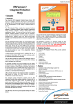
MEC-1 – Earth Continuity Protection Relay User Manual Part Number: 167261 Revision: 0 – November 2013 Designed and manufactured in Australia by Ampcontrol CSM Pty Ltd Ampcontrol CSM Pty Ltd - ABN 35 000 770 141 ECDB006 MEC-1 User Manual Rev 0 – 11/13 WARNING! CAUTION! This safety alert symbol identifies important safety messages in this manual and indicates a potential risk of injury or even death to personnel. When you see this symbol, be alert, your safety is involved, carefully read the message that follows, and inform other operators. This safety alert symbol identifies important information to be read in order to ensure the correct sequence of work and to avoid damage or even destruction of the equipment, and reduce any potential risk of injury or death to personnel. Supplementary information not directly affecting safety or damage to equipment. Carefully read the message that follows, and inform other relevant personnel. Information concerning possible impact on the environment and actions required for prevention and proper response. MEC-1 USER MANUAL R0 2/10/2014 14:13 Page 2 of 18 Ampcontrol CSM Pty Ltd - ABN 35 000 770 141 ECDB006 MEC-1 User Manual Rev 0 – 11/13 Copyright Notice The Ampcontrol MEC-1 described in this document is the property of AMPCONTROL PTY LTD. It is furnished under a license agreement and is to be used only in accordance with the terms of the agreement. No part of the hardware or documentation may be reproduced, transmitted, transcribed, stored in a retrieval system, or translated into any language or computer language, in any form or by any means, without prior written permission of AMPCONTROL PTY LTD. Disclaimer While every effort has been made to assure the accuracy and clarity of this document, AMPCONTROL PTY LTD assumes no liability resulting from any omissions in this document, or from misuse of the information obtained herein. The information in this document has been carefully checked and is believed to be entirely reliable with all of the necessary information included. AMPCONTROL PTY LTD reserves the right to make changes to any products described herein to improve reliability, function, or design, and reserves the right to revise this document and make changes from time to time in content hereof with no obligation to notify any persons of revisions or changes. AMPCONTROL PTY LTD does not assume any liability arising out of the application or any use of any product or circuit described herein; neither does it convey license under its patent rights or the rights of others. Before You Begin We would like to take a moment to thank you for purchasing the Ampcontrol MEC-1 Earth Continuity Relay. WARNING! To become completely familiar with this equipment and to ensure correct operation, we strongly recommend that you take the time to read and thoroughly understand this user manual. Ampcontrol CSM Contact Details 7 Billbrooke Close, Cameron Park, NSW, 2285 P +61 2 4903 4800 | F +61 2 4903 4888 EMAIL: [email protected] WEB: www.ampcontrolgroup.com MEC-1 USER MANUAL R0 2/10/2014 14:13 Page 3 of 18 Ampcontrol CSM Pty Ltd - ABN 35 000 770 141 ECDB006 MEC-1 User Manual Rev 0 – 11/13 TABLE OF CONTENTS 1 SAFETY AND OTHER WARNINGS.............................................................................5 1.1 Safe Use of Equipment......................................................................................5 2 RECEIVING AND STORAGE.....................................................................................6 2.1 Receiving.......................................................................................................6 2.2 Inspection ......................................................................................................6 2.3 Storage after Delivery .......................................................................................6 2.4 Unpacking of Equipment ....................................................................................6 3 INSTALLATION .....................................................................................................7 3.1 General Warnings ............................................................................................7 3.2 Mandatory Installation Practices ..........................................................................7 4 MEC-1 RELAY OVERVIEW .......................................................................................8 4.1 Mechanical Arrangement ...................................................................................9 4.2 Electrical Connections ..................................................................................... 10 5 COMMISSIONING AND CALIBRATION ..................................................................... 12 5.1 Earth Continuity Test – Series Resistance ............................................................ 12 5.2 Earth Continuity Test – Shunt Resistance ............................................................ 12 5.3 Remote Start Function .................................................................................... 12 6 AS/NZS 2081 PROTECTION FUNCTION: EARTH CONTINUITY ..................................... 13 6.1 Series Resistance .......................................................................................... 13 6.2 Shunt Resistance........................................................................................... 13 6.3 Remote Start ................................................................................................ 14 6.4 Latching mode .............................................................................................. 14 6.5 Manual reset procedure ................................................................................... 14 7 OPERATION SUMMARY ........................................................................................ 15 7.1 DIP Switches Configuration .............................................................................. 15 7.2 Rotary Switches Configuration .......................................................................... 15 7.3 Indication LEDs ............................................................................................. 15 7.4 Fault Indication .............................................................................................. 16 7.5 Starting the MEC-1 ......................................................................................... 16 8 SERVICE, MAINTENANCE & DISPOSAL ................................................................... 17 8.1 Equipment Service ......................................................................................... 17 8.2 Equipment Maintenance .................................................................................. 17 8.3 Disposal ...................................................................................................... 17 9 SPECIFICATIONS ................................................................................................ 18 10 EQUIPMENT LIST............................................................................................... 18 APPENDIX ...............................................................Error! Bookmark not defined. MEC-1 USER MANUAL R0 2/10/2014 14:13 Page 4 of 18 Ampcontrol CSM Pty Ltd - ABN 35 000 770 141 ECDB006 MEC-1 User Manual Rev 0 – 11/13 1 SAFETY AND OTHER WARNINGS For safety reasons, the MEC-1 must be installed, operated and serviced only by competent personnel. Read and understand this instruction manual completely before installing, operating or servicing this equipment. Failure to install or operate this instrument in accordance with the instructions contained in this manual may create hazardous operating conditions. 1.1 Safe Use of Equipment The equipment supplied has been manufactured according to the state of the art, and designed to ensure a safe operation. The equipment may only be used within the design parameters. The instructions within this manual must be observed as an aid towards achieving maximum safety during operation. The owner/user is responsible for observing the following instructions: 1.1.1 Changes to Equipment Changes in the design and modifications to the equipment are not permitted. Unauthorised changes made to the hardware or operating firmware will void the manufacturer's warranty, and may compromise the integrity of the system into which it is installed and other connected equipment. 1.1.2 Equipment Knowledge Experience with, or understanding of, this equipment is essential for the safe installation and removal of the equipment. Therefore, in case of a question on how to safely proceed, contact Ampcontrol immediately. 1.1.3 Manual Handling Precautions have been taken to ensure all equipment is safe to handle and free from sharp edges. However care should always be taken when handling enclosures and gloves should be worn. 1.1.4 Installation Correct operation and safety depend on the MEC-1 and associated equipment being installed correctly. Mechanical and or electrical installation and maintenance of plant and equipment must only be carried out by appropriately qualified personnel and must be tested thoroughly prior to operation. 1.1.5 Operation As safety depends on the MEC-1 functioning correctly it is highly recommended that all safety functions of the MEC-1 be periodically tested to ensure correct operation. MEC-1 USER MANUAL R0 2/10/2014 14:13 Page 5 of 18 Ampcontrol CSM Pty Ltd - ABN 35 000 770 141 ECDB006 MEC-1 User Manual Rev 0 – 11/13 2 RECEIVING AND STORAGE 2.1 Receiving All possible precautions are taken to protect the equipment against damage or losses during shipment, however before accepting delivery, check all items against the packing list or bill of loading. If there are shortages or evidence of physical damage, notify Ampcontrol immediately. Notify Ampcontrol within 7 days (maximum) in case of shortages or discrepancies, according to the packing list. This action will help ensure a speedy resolution to any perceived problems. Keep a record of all claims and correspondence. Photographs are recommended. Where practicable do not remove protective covers prior to installation unless there are indications of damage. Boxes opened for inspection and inventory should be carefully repacked to ensure protection of the contents or else the parts should be packaged and stored in a safe place. Examine all packing boxes, wrappings and covers for items attached to them, especially if the wrappings are to be discarded. 2.2 Inspection Equipment that is found to be damaged or has been modified away from its published specification must not be used. Please contact Ampcontrol if the equipment is suspected to be different than that ordered or if it does not match the published specifications. 2.3 Storage after Delivery When the equipment is not to be installed immediately, proper storage is important to ensure protection of equipment and validity of warranty. All equipment should be stored indoors, preferably on shelves and protected from the elements. 2.4 Unpacking of Equipment The method of packing used will depend on the size and quantity of the equipment. The following cautions should be interpreted as appropriate. CAUTION! Take care when unpacking crates as the contents may have shifted during transport. The disposal of packaging materials, replaced parts, or components must comply with environmental restrictions without polluting the soil, air or water. Ensure that any timber and cardboard used as packaging is disposed of in a safe and environmentally responsible manner. Where possible, dispose of all waste products i.e. oils, metals, plastic and rubber products by using an approved recycling service centre. MEC-1 USER MANUAL R0 2/10/2014 14:13 Page 6 of 18 Ampcontrol CSM Pty Ltd - ABN 35 000 770 141 ECDB006 MEC-1 User Manual Rev 0 – 11/13 3 INSTALLATION 3.1 General Warnings These instructions have been designed to assist users of the MEC-1 relay with installation. Before the MEC-1 can be installed, there are a number of things that need to be considered and understood to prevent incorrect or unsafe operation of the MEC-1 or the system into which it is installed. Along with relevant competence, and an understanding of the target application, the following points should be considered: 3.1.1 Ensure that the information provided in this user manual is fully understood. It is extremely important that the limitations and functionality of the MEC-1 are understood to prevent incorrect installation and use from creating a potentially dangerous risk. If in doubt as to the nature of the limitations or their implication, consult a competent authority such as a supervisor or Ampcontrol technical representative. 3.1.2 Ensure that the application into which the MEC-1 relay is being installed has been properly defined, designed and approved. Any system intended to mitigate the risk of injury needs to be properly designed and implemented. Such a system must be the result of structured risk analysis with the outcomes used to define the system requirements. These requirements, in turn, will guide the choice of instrumentation, logic solvers and actuators needed to implement the system. Understanding the needs of the system will ensure proper selection of equipment. 3.1.3 Ensure that the MEC-1 relay will properly perform the required functions within the system design. It is important to understand how the MEC-1 is intended to interact with other equipment within a system. For safe and reliable use, it is crucial that neither the MEC-1’s logical operation nor its signalling be compromised by incompatibilities with connected equipment. 3.1.4 Modifications of any form to the MEC-1 relay are prohibited. The MEC-1 as supplied has been designed and manufactured to comply with the requirements of protection standards. If modifications of any form are made to the MEC-1, the equipment may no longer be fit for use. If any modifications or damage to the MEC-1 is evident, do not use the equipment and contact Ampcontrol for advice. 3.2 Mandatory Installation Practices The following information must be adhered to when installing the MEC-1. Failure to adhere to this information may give rise to unsafe operation. Using the MEC-1 in a manner that exceeds its electrical, functional or physical specifications, or in a way that is contrary to its operating restrictions, may create risks to personnel and/or equipment resulting in injury or death. The MEC-1 must be powered within the specified voltage range. The installation of the MEC-1 must be carried out by suitably trained and qualified personnel. Identification labels fixed to the MEC-1 must not be damaged, removed or covered before, during or after installation. The installation is to be in accordance with the relevant installation Standards/Codes of Practice. Modifications must not be made to any part of the MEC-1. As supplied, the unit is built to, and complies with the relevant standards. Modification to its construction will render the unit non-compliant. Complete and accurate records of the installation must be kept as part of the site installation. MEC-1 USER MANUAL R0 2/10/2014 14:13 Page 7 of 18 Ampcontrol CSM Pty Ltd - ABN 35 000 770 141 ECDB006 MEC-1 User Manual Rev 0 – 11/13 4 MEC-1 RELAY OVERVIEW The MEC-1 is an electrical protection relay designed for operation in metalliferous mining applications. It provides earth continuity protection in accordance with AS/NZS 2081:2011 ensuring the integrity of the earth connection through a trailing or reeling cable is maintained. Earth Continuity protection is another layer of protection that, along with earth leakage protection, can help keep step and touch voltage potentials at a safe level by ensuring the earth resistance is below a determined safe level. The MEC-1 relay is based on microprocessor digital logic, and features a user friendly LED and switch interface. It is installed within a compact, DIN rail mounted unit with pluggable connectors that can easily be changed out in the event of a problem with the relay. Key Features Compact size DIN rail mounted Simple wiring and installation Six (6) settings for trip time Six (6) settings for trip level AS/NZS 2081:2011 Compliant Typically the MEC-1 relay will be connected to the pilot conductor of a trailing or reeling cable. With the pilot conductor terminated to earth through a diode, the relay measures the resistance of the pilot-earth loop (series resistance), to ensure the integrity of the earth conductors, and the pilot to earth resistance (shunt resistance), to ensure the integrity of the pilot-earth loop. If these tests fail the MEC-1 will trip, de-energising its output relay which can be used to switch a contactor, circuit breaker or for signalling. The MEC-1 can be configured for latching or non-latching operation and has a remote start option. CAUTION! A safe resistance level for the pilot-earth loop should be determined by risk assessment and analysis of the system. MEC-1 USER MANUAL R0 2/10/2014 14:13 Page 8 of 18 Ampcontrol CSM Pty Ltd - ABN 35 000 770 141 ECDB006 MEC-1 User Manual Rev 0 – 11/13 4.1 Mechanical Arrangement 4.1.1 Enclosure The MEC-1 is housed in a plastic enclosure and is rated IP20. The dimensions are shown in Figure 1 below (117x45x114mm): 117 114 45 Figure 1: MEC-1 enclosure dimensions 4.1.2 Mounting arrangement The MEC-1 enclosure is designed to be mounted on a standard 35mm DIN rail. The pilot and earth connections are located at the top of the enclosure and the power and user inputs and outputs are located at the bottom of the enclosure. The fascia of the relay includes two (2) adjustable DIP switches and two (2) rotary switches for configuration of relay settings and five (5) indication LEDs to assist in fault finding. MEC-1 USER MANUAL R0 2/10/2014 14:13 Page 9 of 18 Ampcontrol CSM Pty Ltd - ABN 35 000 770 141 ECDB006 MEC-1 User Manual Rev 0 – 11/13 4.2 Electrical Connections Once the MEC-1 relay has been mounted at a suitable location, it is necessary to wire it correctly. Figure 2 shows a typical wiring diagram for the application of the MEC-1 relay. N.O USER PUSHBUTTON OPTIONAL STOP RST + POWER SUPPLY OPTIONAL REMOTE START DIODE PILOT USER DEFINED RESISTOR 100Ω 1000V, 1A EARTH Figure 2: MEC-1 Typical Electrical Application The table below lists the terminal connections into the MEC-1 relay. Terminal 1 2 3 4 Label RST + NC1 Description Reset Power Supply Positive Power Supply Negative Relay Output Normally Closed Contact 1 5 6 7 8 NO1 COM1 NO2 COM2 Relay Output Normally Open Contact 1 Relay Output Common Contact 1 Relay Output Normally Open Contact 2 Relay Output Common Contact 2 9 10 11 12 NC NC NC NC Not connected Not connected Not connected Not connected 13 14 15 16 Pilot NC NC Earth Pilot connection Not connected Not connected Earth MEC-1 USER MANUAL R0 2/10/2014 14:13 Page 10 of 18 Ampcontrol CSM Pty Ltd - ABN 35 000 770 141 ECDB006 MEC-1 User Manual Rev 0 – 11/13 4.2.1 Supply The appropriate power supply for the MEC-1 relay is 24VAC/DC ±20%. 4.2.2 Pilot Terminal The pilot terminal provides a connection through which the MEC-1 performs resistance measurements. Typically the pilot terminal will be connected to the pilot conductor of a trailing or reeling cable. The load end of the pilot conductor will then be terminated with a diode to earth, creating a return path through the earth conductors of the cable to the main earth point of the outlet and then to the MEC-1 earth terminals. The primary function of the MEC-1 relay is to verify the resistance of this pilot earth-loop is below a selectable level. 4.2.3 Earth Terminals The earth terminals provide the MEC-1 with an earth reference for the pilot resistance measurement. At least one of these terminals must be connected directly to the outlet’s main earth point. 4.2.4 Reset - Optional This is an active high input that allows MEC-1 trips to be reset in latching mode, after the fault has been cleared. The reset input has no affect in non-latching mode. The Reset input should be connected to the MEC-1’s ‘+’ terminal via a normally open switch with a minimum rating of the supply voltage. 4.2.5 Relay Contacts The default position of the relay contacts (Normally Open or Normally Closed) is described on the MEC-1 front label and Figure 2. The relay contacts will change state when the MEC-1 is started (Status LED flashing) and will return to the default state when the MEC-1 trips. The relay contacts are rated for 1A @ 110Vac and 1A @ 30Vdc (Resistive). 4.2.6 External Fuse The MEC-1’s Pilot Terminal is designed such that in the event of a phase to pilot fault the voltage will be clamped at the pilot terminal to a safe level and protects the relay from damage. However this connection can only withstand 5.25A for 1s. The MEC-1 relay must, therefore, be installed in a system with earth fault current limitation of 5A or less and an earth fault clearance time of less than 1s. Alternatively a 3A external fuse rated to system voltage can be installed between the MEC-1’s pilot terminal and the pilot conductor. 4.2.7 Stop Button - Optional The stop button should be a normally closed switch installed in the pilot conductor. When opened, the MEC-1 will detect an open circuit pilot and trip on open circuit. 4.2.8 Start Button and Resistor - Optional When remote start mode is selected a 100Ω, 1%, 5W resistor must be installed in series with the pilot conductor. The start button is then installed in parallel to this resistor. The start button should be a normally open switch. MEC-1 USER MANUAL R0 2/10/2014 14:13 Page 11 of 18 Ampcontrol CSM Pty Ltd - ABN 35 000 770 141 ECDB006 MEC-1 User Manual Rev 0 – 11/13 5 COMMISSIONING AND CALIBRATION Prior to being put into service, the electrical protection system must be correctly commissioned. This manual does not cover system commissioning; the full scope of commissioning tests should be determined during the risk assessment or FMEA covering the design of the electrical protection system. The following test can provide guidance on checking the correct operation of the MEC-1 during commissioning. This is not intended to provide an exhaustive commissioning checklist, but should be considered to be a minimum set of tests. The Earth Continuity function performs two measurements to ensure the integrity of the pilot-earth loop; Series resistance measurement and shunt resistance measurement. 5.1 Earth Continuity Test – Series Resistance The series resistance measurement can be verified by installing a resistor which is a minimum of 3Ω above the selected trip level, or creating an open circuit, in series with the pilot conductor and verifying that the MEC-1 relay trips within the selected trip time and indicates an open circuit fault. 5.2 Earth Continuity Test – Shunt Resistance The shunt resistance measurement can be verified by installing a resistor which is 1kΩ or less, or creating a short circuit, between the pilot conductor and earth, and verifying that the MEC-1 relay trips within the selected trip time and indicates a short circuit fault. 5.3 Remote Start Function The remote start function can be verified by repeating the two previous tests in the remote start mode with the remote start resistor installed. MEC-1 USER MANUAL R0 2/10/2014 14:13 Page 12 of 18 Ampcontrol CSM Pty Ltd - ABN 35 000 770 141 ECDB006 MEC-1 User Manual Rev 0 – 11/13 6 AS/NZS 2081 PROTECTION FUNCTION: EARTH CONTINUITY The primary function of the MEC-1 relay is to provide Earth Continuity protection in accordance with AS/NZS 2081: 2011. This protection ensures the integrity of the earth connection between an outlet and a load via the pilot conductor in the cable. In a typical installation the MEC-1’s pilot terminal will be connected to the pilot conductor of a trailing or reeling cable. The load end of the pilot conductor will then be terminated with a diode to earth, creating a return path through the earth conductors of the cable to the main earth point of the outlet and then to the MEC-1’s earth terminals. The MEC-1 measures the resistance of this pilot-earth loop (series resistance) and the pilot resistance to earth (shunt resistance). If the pilot-earth loop is not healthy (series resistance greater than the selected trip value or shunt resistance lower than 1.25kΩ), a trip occurs which de-energises the output relay within the selected trip time. The trip can be configured as latching or non-latching. This allows the user to choose if the trip is manually or automatically reset once the pilot - earth loop is healthy. CAUTION! Cable parameters are important to the correct operation of the Pilot E/C function. Resistance & capacitance values limit the length of cable that the relay can drive. 6.1 Series Resistance The MEC-1 relay measure the series resistance of the pilot-earth loop by applying a positive voltage to the pilot conductor and measuring the pilot current. If the series resistance is detected to be above the user selected level, the MEC-1 de-energises its output relay and the LEDs on the front panel will indicate an open circuit fault. The pilot-earth loop resistance will still continuously be monitored even in the event of a trip. The MEC-1 cannot be re-started until the fault has been cleared. A power cycle will not reset the trip. In non-latching mode, the MEC-1 will automatically reset after the fault has been cleared. In latching mode, a manual reset is needed after the fault has been cleared. The trip level and time can be selected using the rotary switch on the front panel. 6.2 Shunt Resistance The MEC-1 measures the shunt resistance (pilot to earth) by applying a negative voltage to the pilot conductor and measuring the pilot current. If the shunt resistance is detected to be below 1.25kΩ, the MEC-1’s output relay will be de-energised and the LEDs on the front panel will indicate a short circuit fault. The shunt resistance will still continuously be monitored even in the event of a trip. The MEC-1 cannot be re-started until the fault has been cleared. A power cycle will not reset the relay. In non-latching mode, the relay will automatically reset after the fault has been cleared. In latching mode, a manual reset is needed after the fault has been cleared. The trip time can be selected using the rotary switch on the front panel. MEC-1 USER MANUAL R0 2/10/2014 14:13 Page 13 of 18 Ampcontrol CSM Pty Ltd - ABN 35 000 770 141 ECDB006 MEC-1 User Manual Rev 0 – 11/13 6.3 Remote Start Remote start mode can be selected via the DIP switches at the front of the panel. Switching to or from remote start mode while the power is applied will cause a trip (the relay will de-energise and the Start Timed Out LED will come ON). In remote start mode, a 100Ω resistor (1%, 5W) must be connected in series with the pilot circuit and a normally open button connected in parallel to this resistor. The loop resistance of the circuit will then be 100Ω plus the resistance of the cable. To start the MEC-1 in remote start mode the following sequence must be followed: 1. All trips must be clear. 2. The start resistor must be detected in the pilot circuit. 3. The start button must be pressed for a minimum of 500ms. 4. The start button must be released within 15s or “Start Button timed out” trip will occur. The start timed out fault is automatically reset once the start resistor is detected (A manual reset is not required). 6.4 Latching mode Latching mode can be selected via the DIP switches at the front panel. When a fault occurs in latching mode the trip will be latched, preventing the MEC-1 from starting (even if the fault is cleared), until a manual reset occurs. In latching mode, if a fault occurs, the corresponding LED will be turned on and the trip will be latched. If another fault occurs, while the previous trip is still latched, the LED corresponding to that fault will flash. 6.5 Manual reset procedure To use the reset function, the user must connect a switch (typically a NO momentary pushbutton) between the RST input and the positive of the supply (see ‘Electrical Connections’ section 4.3 for more information). In latching mode, the user must manually reset the unit after a fault has occurred. The procedure is as follows: 1. Clear the fault. 2. Press the reset button for a minimum of 500ms. MEC-1 USER MANUAL R0 2/10/2014 14:13 Page 14 of 18 Ampcontrol CSM Pty Ltd - ABN 35 000 770 141 ECDB006 MEC-1 User Manual Rev 0 – 11/13 7 OPERATION SUMMARY 7.1 DIP Switches Configuration 7.1.1 Remote Start Switch Position Off (left) On (right) Function Remote Start disabled. A remote start button (with a 100Ω resistor) must not be installed Remote Start Enabled. A remote start button (with a 100Ω resistor) must be installed 7.1.2 Latching Switch Position Off (left) On (right) Function Latching mode disabled. Trips will be automatically reset after the fault has been cleared. Latching mode enabled. Trips must be manually reset after the fault has been cleared. 7.2 Rotary Switches Configuration 7.2.1 Trip Level selection The user can select the trip level via one of the rotary switches at the front of the unit. The trip level represents the threshold for the series resistance. If the resistance is measured to be greater than this threshold ±3Ω, a trip will occur. The allowed values for the trip level setting are 10Ω, 15Ω, 20Ω, 25Ω, 35Ω, and 45Ω. The shunt resistance trip level is fixed at 1.25kΩ. A trip will occur if the pilot to earth resistance is detected to be below this level. 7.2.2 Trip Time Selection The user can select the trip time via one of the rotary switches at the front of the unit. The trip time represents the delay after which a trip condition has occurred when the MEC-1 relay will de-energise. The allowed settings for the trip time are 50ms, 100ms, 200ms, 300ms, 400ms, and 500ms. 7.3 Indication LEDs 7.3.1 Status (Green) LED state Off Flashing On Indication Power Off Power is ON and MEC-1 is running (relay contacts switched to the non-default state) Power is ON but MEC-1 is not running (relay contacts in the default state) 7.3.2 Healthy (Green) LED state Off Flashing On MEC-1 USER MANUAL R0 Indication Pilot is not healthy (series resistance above the selected setting or shunt resistance below 1.25kΩ) N/A Pilot is healthy (series resistance below the selected setting and shunt resistance above 1.25kΩ) 2/10/2014 14:13 Page 15 of 18 Ampcontrol CSM Pty Ltd - ABN 35 000 770 141 ECDB006 MEC-1 User Manual Rev 0 – 11/13 7.3.3 Short Circuit (Red) LED state Off Indication Shunt resistance above 1.25kΩ Non-latch mode: Shunt resistance is below 1.25kΩ but for less than trip time setting Latch mode: the relay has tripped on series resistance and shunt resistance is now below 1.25kΩ Shunt resistance below 1.25kΩ Flashing On 7.3.4 Open Circuit (Red) LED state Off Indication Series resistance is below trip setting Non-latch mode: Series resistance is above trip setting but for less than trip time setting Latch mode: the relay has tripped on shunt resistance and series resistance is now above trip setting Series resistance is above trip setting Flashing On 7.3.5 Start Timed Out (Red) LED state Off Flashing On Indication Start button not pressed Start button is pressed Start button has timed out (held down for more than 15s) 7.4 Fault Indication CAUTION! When an internal fault occurs, all the LEDs will be flashing together and the measurements can no longer be trusted. A power cycle is needed to reset this state. If this happens repetitively, please contact Ampcontrol as the unit may be damaged. The MEC-1 continuously checks the health of its internal circuitry. If these checks fail, the MEC-1 will show an internal fault by flashing all LEDs and returning the relay contacts to the default position. 7.5 Starting the MEC-1 When first powered, the MEC-1 will begin checking its internal circuitry as well as the pilot circuit. If no faults are detected within 1.7s the MEC-1 will be ready to start. If remote start mode is not selected the MEC-1 will automatically start, energising its output relay. If remote start mode is selected the relay will wait for the start button to be pressed. After a trip has occurred and the fault cleared, the MEC-1 can be reset and re-started depending on the configured modes: Latching Mode No No Yes Yes MEC-1 USER MANUAL R0 Remote Start Mode No Yes No Yes Starting the MEC-1 Automatic re-start 1s after the fault has been cleared. Press the start button a minimum of 1s after the fault has been cleared. Automatic re-start immediately after manual reset Press the start button after manual reset 2/10/2014 14:13 Page 16 of 18 Ampcontrol CSM Pty Ltd - ABN 35 000 770 141 ECDB006 MEC-1 User Manual Rev 0 – 11/13 8 SERVICE, MAINTENANCE & DISPOSAL 8.1 Equipment Service The MEC-1 requires no internal servicing during its normal operating life. A number of external system based checks should however be completed on a regular basis. These ‘routine inspections’ must be carried out by suitably trained people with knowledge of the MEC-1 and the systems into which it is fitted. Routine inspections may take the form of either visual-only checks, or visual and ‘hands-on’ checks. 8.1.1 Visual Only Inspections A basic visual inspection focuses on looking at the installation for signs of physical damage, water or dust ingress and the condition of cables and labels. This type of inspection may involve opening cabinets to gain access to the MEC-1 and other equipment. This level of inspection may also include cleaning display windows that have become obscured by dirt. Observations would typically be: Check that equipment enclosures, cable trays, conduits, etc. are in good order with no physical damage. Check that sealed wall boxes are free from water and dust ingress internally. Door seals are in good condition. Check that connected cables are free from cuts, abrasions and obvious signs of damage. Cable restraints are in good order and correctly fitted. Check that labels on equipment, wall boxes and cables are present and in good condition (especially certification labels). Check that no modifications have been carried out to installed equipment. 8.1.2 Hands-On (Detailed) Inspections A more detailed inspection would include all of the elements of a visual inspection, plus some checks that cover the integrity of connections, fixtures and fittings. In addition to basic visual observations, more detailed integrity checks would involve: Verify that equipment housings, wall boxes and other mechanical fixtures are secured in place. This includes terminal box lids, tightness of cable glands, integrity of wall-box mountings, security of equipment fixing to walls/DIN rails etc. Verify all electrical connections are secure with no loose screw terminals or DIN rail terminals not fitted to rails etc. 8.2 Equipment Maintenance WARNING! The MEC-1 relay has no user-serviceable parts. All repairs must be carried out by Ampcontrol only. If a fault develops, return the relay to Ampcontrol for repair. It is essential that no attempt be made to repair the MEC-1 as any attempt to dismantle or repair the MEC-1 can seriously compromise the safety of the unit. It is recommended that the electrical protection system incorporating the MEC-1 be subject to regular functional tests at intervals determined by risk assessment or FMEA. These intervals typically coincide with periodic maintenance checks and will cover (but not limited to) tests such as earth continuity tests. 8.3 Disposal The electronic equipment discussed in this manual must not be treated as general waste. By ensuring that this product is disposed of correctly you will be helping to prevent potentially negative consequences for the environment and human health which could otherwise be caused by incorrect waste handling of this product. MEC-1 USER MANUAL R0 2/10/2014 14:13 Page 17 of 18 Ampcontrol CSM Pty Ltd - ABN 35 000 770 141 ECDB006 MEC-1 User Manual Rev 0 – 11/13 9 SPECIFICATIONS Supply Voltage Voltage Temperature Range 24VAC/DC ± 20%, 5W -20°C ≤ Ta ≤ 65°C Relay Contacts Contacts Ratings 2 x NO / 1 x NC / 2 x COM 1A @ 110Vac – 1A @ 30Vdc (Resistive) Earth Continuity Protection: AS/NZS 2081: 2011 Series Resistance Trip 10Ω, 15Ω, 20Ω, 25Ω, 35Ω, 45Ω Settings (± 3Ω) Shunt Resistance 1.25kΩ Trip Time Settings 50ms, 100ms, 200ms, 300ms, 400ms, 500ms Pilot Measurement Voltage ±24Vdc Optional Start Button 100Ω, 1%, 5W Mechanical Dimensions Weight IP Rating 117x45x114mm 503g IP20 10 EQUIPMENT LIST Part Number 167261 Description MEC-1 EARTH CONT Accessories 115119 169732 NA MODULE PTB PILOT TERMINATION FOR ECB/D/M RES 100R 5W 1% Normally Open Reset Button - Contact Ampcontrol MEC-1 USER MANUAL R0 2/10/2014 14:13 Page 18 of 18