1
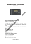
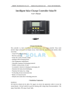
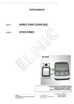
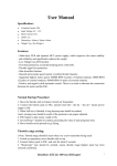
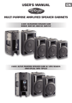
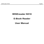
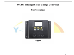
UEIUA Intelligent Solar Charge Controller User’s Manual Please read this manual carefully before you use this product. Chooses us, chooses the specialty! Website: Http://www.ueiua.com 1 UEIUA Catalogue 1. Product Introduction .................................................................................................................... 3 2. Installation ................................................................................................................................... 4 3. Operation ..................................................................................................................................... 5 4. Common Breakdown and Disposal ........................................................................................... 11 5. Quality Assurance ..................................................................................................................... 13 6. Technical Data ........................................................................................................................... 15 Chooses us, chooses the specialty! Website: Http://www.ueiua.com 2 UEIUA 1. Product Introduction This controller is a kind of intelligent, multi-purpose solar charge and discharge controller. These serial products adopt customized LCD display screen, which makes the operation on the interface rather convenient. All the controlling parameters can be reset flexibly to satisfy your different needs. This controller has the following features: Visual LCD graphic symbol ●Brief key operation Automatic identification system voltage level ●Intelligent PWM charge mode Automatic temperature compensation ●Adjustable charge-discharge control parameters Settable operating modes of loads ●Overload & short circuit protection Remote monitoring and control function (custom) ●Battery reverse-discharge protection Battery low voltage disconnection (LVD) ●Battery reverses connection protection Accumulated function of charge and discharge ampere hours Chooses us, chooses the specialty! Website: Http://www.ueiua.com 3 UEIUA 2. Installation Installation: ① Get ready the related tools and cables. We suggest you to choose the right cables to ensure the current density <4mm²and this is good for reducing cable voltage drop. Recommendation: 20A、30A using 16mm²cable, 50A 、60Ausing 25mm²cable. Check whether the installation place accords with the relative safety requirements. Please avoid installing and using the controller under the following conditions: damp, dusty places or places with flammable, explosive and corrosive gases ② Install the controller into a fixed vertical plane. Please refer to Chapter 5 for more detailed info about the spacing between the installing holes. In order to make the controller have a good thermal condition, please spare 10cm above & below the controller. ③ As shown on the right, connect the (1) Loads, (2) Battery and (3) Solar Panel with the controller in order. Pay attention to connect the loads, battery, solar panel and controller of same polarity. ④ Put the external thermal sensor into the interface of thermal-sensor on the left of the controller. The temperature sensor should be similar space with battery. (Otherwise, the controller will control the parameters of all wrong temperature compensation.) ⑤ If you have remote monitoring and control function, please insert one end of the included communication wire on the right of the controller (communication port), the other end to connect to the host computer. Demolition: To avoid the accident, please dismantle solar panels, battery and load s from the controller. in order. Attention:Connecting the battery reversed will not damage the controller, but will cause safety risk on your loads. Chooses us, chooses the specialty! Website: Http://www.ueiua.com 4 UEIUA 3. Operation 1. Description of LCD graphic symbol :Stop supplying power for Loads :Supplying power for Loads the load circuit without current :Stop the battery charging :Bulk charging the battery :Float charging the battery :The load circuit with current :The system is working correctly :Load :The system is not working correctly :Solar Panel :Battery charge capacity display :Load sensor control :Battery :Load timer control 2. Description of button function: : Interfaces circular togging button. Use this button can realize the toggling circularly among the interfaces. The circular order is as follows: as shown as figure 1 : Adjustment of parameters plus buttons. Besides, under parameter view condition, press the button for over 5 seconds, and all the parameter will recover to the ex-work setting state. Chooses us, chooses the specialty! Website: Http://www.ueiua.com 5 UEIUA : Adjustment of parameters minus button. Besides, at the main interface, this button can turn on or turn off the load. Battery Voltage (main interface) Load working Mode Battery temperature Solar Panel charge current Load discharge current Accumulated charging power(Ah) High Voltage Low voltage Low Voltage Accumulated Disconnection (HVD) Reconnection (LVR) Disconnection (LVD) Discharging power (Ah) Figure 1 3. View and set the parameters After the controller electrifies right, it will enter into the displaying interface of batter voltage. This interface is the main interface of the controller. Press the button to go through the interface of the following parameters. If that interface could be reset, press the button for long(>5seconds,and the number on the interface start to flicker), then it enter the setting interface of this parameter. After finishing the setting, press Chooses us, chooses the specialty! Website: Http://www.ueiua.com 6 UEIUA the button for long to exit the setting interface, and the number stop flickering. 3.1 Battery Voltage review As shown as the right figure, the displaying number is the present battery voltage. This interface is the main interface, and it shows the charging & discharge state, battery capacity and battery voltage. 3.2 The load On/Off controlling At the batter voltage review interface, you can press button to turn on or turn off the load, While this button does not have this function at other interface. 3.3 Environmental temperature review As shown on the right, displays the ambient temperature of the controller, the value used for temperature compensation on LVD function. The sensor must be plug in before using the controller. Chooses us, chooses the specialty! Website: Http://www.ueiua.com 7 UEIUA 3.4 Review the generating current of solar panels As shown as the right figure, the displaying number is the generating current of solar panels. 3.5 The load current review As shown as the right figure, the displaying number is the load current. 3.6 Review and clearing the accumulative generating AH of solar panels As shown as the right figure, the displaying number is the accumulative generating AH of solar panels. At this interface, press the button for long(>5seconds), and it can clear accumulative generating AH. 3.7 Review and clearing load accumulative discharging AH As shown as the right figure, the displaying number is the accumulative discharging AH of loads. At this interface, press the button for long(>5seconds) ,and it can clear accumulative discharging AH. Chooses us, chooses the specialty! Website: Http://www.ueiua.com 8 UEIUA 3.8 Review and setting low voltage protection function As shown as the right figure, the displaying number is the protection voltage. And if the battery voltage is lower than protection voltage, the controller will disconnect the load loop to prevent battery from over-discharging. At this interface, press the button for long(>5seconds) ,the number starts to flicker, and it means the controller enters into the interface of setting the protection voltage. Use the key 、 to adjust this parameter. After finishing setting, press the button for long (>5seconds)to exit this interface and the controller can store this setting number. 3.9 Review and setting recovering voltage for low voltage condition As shown as the right figure, the displaying number is the recovery number. After the controller enters into low voltage protection state, when the battery voltage recovers to be higher than the recovery voltage, then the controller will reconnect the load loop automatically. At this interface, press the button for long(>5seconds) ,the number starts to flicker, and it means the controller enters into the interface of setting the recovery voltage. Use the key 、 to adjust this parameter. After finishing setting, press the button for long (>5seconds)to exit this interface and the controller can store this setting number. Chooses us, chooses the specialty! Website: Http://www.ueiua.com 9 UEIUA 3.10 Review and setting the voltage of ceasing charging As shown as the right figure, the displaying number is the voltage of ceasing charging. When the battery voltage reaches up to this voltage, the controller will disconnect the charging loop to prevent the battery from overcharging. After the battery voltage drops, the controller will reconnect the charging loop. At this interface, press the button for long(>5seconds) ,the number starts to flicker, and it means the controller enters into the interface of setting the voltage of ceasing charging. Use the key 、 to adjust this parameter. After finishing setting, press the button for long (>5seconds)to exit this interface and the controller can store this setting number. 3.11 Review and setting the load mode As shown as the right figure, it is the reviewing surface of the load mode. Different numbers represent different load mode. 24h—indicating normal mode, loads are under the condition of supplying power without breakdown. 1h~23h—indicating delayed mode of light control, loads start to supply power after dark and shun down after working for the delayed setting hours Chooses us, chooses the specialty! Website: Http://www.ueiua.com 10 UEIUA 0h—said light control mode, loads start to supply power after dark and stop working after drawn. At this interface, press the button for long(>5seconds) ,the number starts to flicker, and it means the controller enters into the interface of setting the load modes. Use the key 、 to adjust this parameter. After finishing setting, press the button for long(>5seconds)to exit this interface and the controller can store this setting number. 4. Common Breakdown and Disposal 1. Low voltage protection and disposal: If the screen shows as the right figure, it means the battery voltage is lower than the protection voltage. The controller enters into the low voltage protection state and the load loop disconnects. Use the solar panels or charger to charge for the battery .When battery voltage recovers to the protection voltage, the controller will recover to supply power for load and enter into the working state. 2. Overloading protection and disposal: If the screen shows as the right figure, and the light flickers, it mean the current of the load loop is 1.2 times of the rated current within 3 seconds, and The controller is at overload state. After removing some loads, the controller will supply power to the loads automatically within seconds, or you can press Chooses us, chooses the specialty! Website: Http://www.ueiua.com 11 UEIUA button to recover the power supply compulsively. 3. Short -circuit protection and disposal: If the screen shows as the right figure, and the light flickers, it means there happens short-circuit in the load loop, and the controller is at short-circuit protection state. Please check whether the loads are damaged and whether the connecting cables are short-circuit. After eliminating the break down, press the button to recover the power supply for the loads. 4. Breakdown and disposal of solar panels: Sign flickering means the controller do not detect the existence of solar panels. Please check whether the connection with solar panels are in good condition, and check whether the cables connecting the solar panels and controller are in open-circuit condition. 5. Load impulsion breakdown: If the flickers when you turn on the load, it means the starting impulsion current is more than twice of the rated working current. Please restart the controller for times. Chooses us, chooses the specialty! Website: Http://www.ueiua.com 12 UEIUA 5. Quality Assurance 1. Quality assurance should be carried out according to the flowing rules: The product is guaranteed of replacement, returning and repairing within 7days after sale. The product is guaranteed of replacement and repairing within 1 month after sale. The product is guaranteed of repairing within 12 months after sale. 2. If it is not possible to identify the using date of the controller, we would refer to the ex-work date, and prescribe 18 months as the warranty period. We need to charge beyond the warranty period. The controller can be repaired for life no matter when and where you use it. 3. If the controller is damaged by the following causes, we need to charge even if it is in the guarantee period: Do not operate according to the user’s manual. Chooses us, chooses the specialty! Website: Http://www.ueiua.com 13 UEIUA Use the controller under the condition which is beyond the using standard and technical requirements. Repair by yourself or reform by yourself. The inappropriate environmental condition can cause the breakdown and aging of the apparatus. Improper carrying or storage. Regarding to the service of replacement, returning and repairing, you need to retreat the product to our company, and we decide whether to replace or repair after we make clear who should be responsible. Chooses us, chooses the specialty! Website: Http://www.ueiua.com 14 UEIUA 6. Technical Data Rated Voltage 12V/24V AUTO Rated Current 20A 30A 48V 50A 60A 20A 30A 50A Voltage of solar panels ≤50V ≤100V Float charging voltage 13.7V/27.4V 54.8V Low voltage protection 10.7V/21.4V 42.8V Low voltage recovery 12.6V/25.2V 50.4V 60A Characteristic No load loss:≤10mA; Loop voltage drop:≤170mV;Temperature compensation:-4mV/Cell/℃ Working Environment Operating Temperature:-20℃~60℃; Storage temperature:30℃~70; Humidity requirements:≤90%,no condensation Installation cable area ≤7# AWG (16mm2) >3# AWG (25mm2) ≤7# AWG (16mm2) >3# AWG (25mm2) Package size 90 mm×188 mm×48 mm 130 mm×188 mm×62 mm 90 mm×188 mm×48 mm 130 mm×188 mm×62 mm Weight 360g 590g 360g 590g Chooses us, chooses the specialty! Website: Http://www.ueiua.com 15