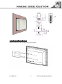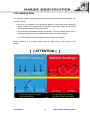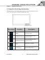
1
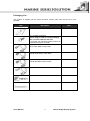
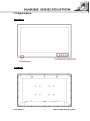
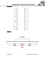
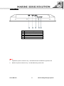
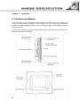
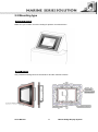
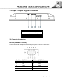
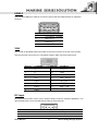
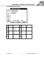
Marine Display (Flat P-CAP series) USERS MANUAL Version: 1.0 R19LXXX-MRXXFP W24LXXX-MRXXFP W26LXXX-MRXXFP Users Manual 19.0 inch Marine Display System 24.0 inch Marine Display System 26.0 inch Marine Display System Marine Bridge Display System REVISION HISTORY REVISION 1.00 AUTHOR Austin DATE May. 4, 2015 DESCRIPTION First version release Copyright @2013 Winmate Communication INC. Users Manual Marine Bridge Display System IMPORTANT SAFETY INSTRUCTIONS Please read these instructions carefully before using the product and save for later reference. Follow all warnings and instructions marked on the product. Unplug this product from the wall outlet before cleaning. Clean the product with a damp soft cloth. Do not use liquid or aerosol cleaners as it may cause permanent damage to the screen. Do not use this product near water. Do not place this product on an unstable cart, stand, or table. The product may fall, causing serious damage to the product. This product should be operated from the type of power indicated on the marking label. If you are not sure of the type of power available, consult your dealer or local power company. This product is equipped with a 3-wire grounding type plug, a plug having a third (grounding) pin. This plug will only fit into a grounding-type power outlet. This is a safety feature. If you are unable to insert the plug into the outlet, contact your electrician to replace your obsolete outlet. (For AC version only) Do not defeat the purpose of the grounding-type plug. Do not allow anything to rest on the power cord. where persons will walk on the cord. Do not locate this product Never push objects of any kind into this product through cabinet slots as they may touch dangerous voltage points or short out parts that could result in a risk of fire or electric shock. Never spill liquid of any kind on the product. Do not attempt to service this product yourself, as opening or removing covers may expose you to dangerous voltage points or other risks and will void the warranty. Refer all servicing to qualified service personnel. Unplug this product from the wall outlet and refer servicing to qualified service personnel under the following conditions: When the power cord or plug is damaged or frayed. If liquid has been spilled into the product. If the product has been exposed to rain or water. If the product does not operate normally when the operating instructions are followed. Adjust only those controls that are covered by the operating instructions since improper adjustment of other controls may result in damage and will often require extensive work by a qualified technician to restore the product to normal operation. If the product has been dropped or the cabinet has been damaged. If the product exhibits a distinct change in performance, indicating a need for service. Users Manual 2 Marine Bridge Display System Packaging List This product is shipped with the items list below. Please make sure that all are in your package. Item Description Note 1 pcs of Users Manual. M4 x 12 black screw bolt. Notice: Only be used to screw the display into a console from the rear side. If you prefer your own bolts, please make sure to use M4 and 30mm in length. 1 pcs of DVI cable DVI-D 24pin Male to 24pin Male 1 pcs of VGA cable D-SUB 15pin Male to 15pin Male 1 pcs of RS232 cable D-SUB 9pin Male to 9pin Female 1 pcs of Power cord 1 pcs of adapter (AC to DC) 1 pcs of terminal block cable Users Manual 3 Marine Bridge Display System Contents IMPORTANT SAFETY INSTRUCTIONS ......................................................... 2 PACKAGING LIST .......................................................................................... 3 CHAPTER 1 INFORMATION ........................................................................ 6 1.1 FEATURES ........................................................................................................................................ 6 1.2 APPEARANCE ................................................................................................................................... 8 CHAPTER 2 INSTALLATION ..................................................................... 12 2.1 GENERAL INSTALLATION................................................................................................................ 12 2.2 MOUNTING TYPE ........................................................................................................................... 13 2.3 INSTALLING NOTE ......................................................................................................................... 15 !!ATTENTION!! ...................................................................................................................... 15 CHAPTER 3 HARDWARE INTRODUCTION.............................................. 17 3.1 CAPACITOR TOUCH KEYS INTRODUCTION ..................................................................................... 17 3.2 INPUT / OUTPUT SIGNALS OVERVIEW ............................................................................................ 18 3.2 CONNECTOR INTRODUCTION ......................................................................................................... 18 CHAPTER 4 OSD OPERATING INTRODUCTION ..................................... 21 4.1 CONTROL KEY DEFINE ................................................................................................................... 21 4.2 OSD MENU INTRODUCE ................................................................................................................ 22 Users Manual 4 Marine Bridge Display System CHAPTER 1 Information Users Manual 5 Marine Bridge Display System Chapter 1 Information The Marine Flat P-CAP Displays are an extraordinary display. Design with transflective panel, dimming brightness, capacitive touch key front panel, projective capacitive multi-touch screen, IP65 proof, wide voltage range power input acceptable, and anti-corrosion protection. Born to the demands of marine applications as navigation, ship automation, and surveillance, rugged industrial and light military applications. All Flat P-CAP Marine Display product designs follow IEC-60945、DNV2.4、IACS E10 Maritime Navigation Certification and Radio-communication Equipment and Systems requirements. 1.1 Features Hyper Dimming Our displays use hyper dimming technology that can control backlight brightness linearly from nearly 0% to 100% by a capacitive touch key front side. In the night vision it’s very suitable for marine applications. Anti-corrosion IP Proof The Flat P-CAP Marine series design with anodized aluminum bezel panel mount. Achieve the anti-corrosion proof in harsh conditions. Wide Voltage Input Range Power Input For marine and transportation power source characteristic, our Flat P-CAP Marine use wide voltage range from 9 to 36V input with 1.5KV isolation protective. (24V is the only voltage approval by DNV certification.) Multi-point capacitive touch screen / Anti-reflection Protection Glass We develop highly compatible mechanical design for each type. Customers can choose high quality multi-point capacitive touch screen or even anti-reflection protection glass for option. Capacitive Touch Key Display Control Flat P-CAP Marine series with five capacitive touch keys on the front panel. These intelligent buttons will help customer operator conveniently. Anti-Shock and Vibration With special anti-vibration and shock mechanical design makes our Panel PC enhanced shock Users Manual Marine Bridge Display System 6 and vibration resistance. International Maritime Certification Approval Flat P-CAP Marine series obtain numbers of certification , including DNV2.4 , IEC60945 4th, IACS-E10 and ECDIS color calibration compliance Customize your marine products Base on our well-experience module competence, we can do very flexible and tailor-made design fulfilling any of customer’s solution. For different panel characteristics, mechanical design, and electronic component, we can make it for you. Approved Marine Display Winmate Marine Display design is followed IEC-60945 Maritime Navigation and Radio-communication Equipment and Systems requirements. The Marine Panel PC series consists wide range sizes from 19 inches to 26 inches. By testing for usability in a ship’s wheelhouse during different ambient light conditions. All these models can fulfill most of the demands in maritime applications especially for navigation, ship automation and maritime surveillance. ※About this Manual The users’ manual introduces basic information about the product, electrical, mechanical and input / output signal specifications. All specification is subject to change without prior notice due to manufacturing reasons. Check in the “Revision History” in front page of this manual for any update reference. Users Manual 7 Marine Bridge Display System 1.2 Appearance Front view Rear view Users Manual 8 Marine Bridge Display System Side view Top view Users Manual 9 Marine Bridge Display System Bottom view No 1 2 3 4 5 Description 1 x USB (Touch screen) 1 x RS232 (Remote control) 1 x DC Power Input 1 x DVI-D 1 x VGA ※Note 1. Appearance just for reference only , outward dimension will different by product size 2. Bottom I/O just for reference only , I/O will different by product size Users Manual 10 Marine Bridge Display System CHAPTER 2 Installation Users Manual 11 Marine Bridge Display System Chapter 2 Installation 2.1 General installation The Marine Panel PC can be applied for several different installation methods. Including panel (flush) mounting, bracket mounting, VESA mounting…etc. For panel (flush) mounting is normally for a ship’s wheelhouse use, it’s easy to follow few steps to fix the display product in customer’s fixture. Check the mechanical and mounting concept as below first. The fixture cut-out dimension and mounting holes based on drawing. Users Manual 12 Marine Bridge Display System 2.2 Mounting type Console Mount Make sure you console cut out are suiting for product cut out dimension Panel Mount Use provided mounting kits to fix the Panel PC and the customer's fixture Users Manual 13 Marine Bridge Display System VESA Mount / Wall Mount VESA and wall mount with mounting kit by special request. Users Manual 14 Marine Bridge Display System 2.3 Installing Note The following common safety precautions should be observed before installing any electronic device: • Strive to use separate, non-intersecting paths to route power and networking wires. If power wiring and device wiring paths must cross make sure the wires are perpendicular at the intersection point. • Keep the wires separated according to interface. The rule of thumb is that wiring that shares similar electrical characteristics may be bundled together. • Do not bundle input wiring with output wiring. Keep them separate. When necessary, it is strongly advised that you label wiring to all devices in the system. !!ATTENTION!! Users Manual 15 Marine Bridge Display System CHAPTER 3 Hardware Introduction Users Manual 16 Marine Bridge Display System Chapter 3 Hardware Introduction 3.1 Capacitor Touch Keys Introduction The Marine Panel PC comes with five display control keys in the lower blue right corner of the screen , it's for quick access to hardware and display OSD control. Touch Keys Users Manual Function Description Power Power on/off control Brightness/Volume To increase brightness of panel /To increase Volume Brightness/Volume To decrease brightness of panel /To decrease Volume Menu Switch to Metro or Desktop ECDIS Mode Switching ECDIS standard range mode (Day / Dust / Night mode) 17 Marine Bridge Display System 3.2 Input / Output Signals Overview No 1 2 3 4 5 Description 1 x USB (Touch screen) 1 x RS232 (Remote control) 1 x DC Power Input 1 x DVI-D 1 x VGA 3.2 Connector Introduction RS232 (Remote Control) Connect Standard D-SUB 9pin connector from your system to connect to the monitor. Pin No. 1 SYMBOL DCD Pin No. 2 SYMBOL DxD 3 TxD 4 DTR 5 GND 6 DSR 7 RTX 8 CTS 9 RI Users Manual 18 Marine Bridge Display System USB2.0 Use standard USB type A cable to connect any device that use USB interface for expansion functions. Pin No. 1 SYMBOL(USB2.0) +5VUSB2.0_CONNA 2 USB_PN1_C 3 USB_PP1_C 4 USB_GND VGA Use D-SUB 15-pin (Male) VGA signal cable to the VGA connector in the rear of PC system, and plug the other end to the TFT LCD display. Fasten cable connectors with screws. Pin No. SYMBOL Pin No. SYMBOL 1 R 9 Vcc(5V) 2 G 10 GND 3 B 11 N/A 4 N/A 12 DDC_DATA 5 GND 13 CRT_HS 6 GND 14 CRT_VS 7 GND DDC_CLK 8 GND 15 CRT _VSDDC _CLK DC Input DC terminal block power source input compact design meets the maritime application. The 3pin terminal block is to be secured that the cable to screw terminal. Pin No. 1 2 3 Users Manual Symbol VIN+ VINGND Description 9-36V DC Input + 9-36V DC Input Ground 19 Marine Bridge Display System CHAPTER 4 OSD Opearting Introduction Users Manual 20 Marine Bridge Display System Chapter 4 OSD Operating Introduction 4.1 Control key define Touch Keys Users Manual Function Description Power Power on/off control Up / increase adjust the value of setting Down/decrease adjust the value of setting Menu Press the MENU button to display the main menu on the screen ECDIS Mode Switching ECDIS standard range mode (Day / Dust / Night mode) 21 Marine Bridge Display System 4.2 OSD Menu Introduce BRICONTRAST BRIGHTNESS CONTRAST ECDIS Day Dusk Night POSITION H-POSITION V-POSITION CHANNEL ANALOG DVI HDMI IMAGE AUTO CLOCK PHASE WHITE BALANCE RECALL YES NO OSD EXIT YES NO USER ╘(RED/GREEN/BLUE) COLOR Users Manual 9300K 6500K ADC BRIGHTNESS 22 Marine Bridge Display System 4.3 Function Introduce BRICONTRAST Press "+" to increase or "-" to decrease the brightness or contrast. BRIGHTNESS: Use to adjust the screen’s brightness CONTRAST: Use to adjust the screen’s contrast POSITION You can adjust the screen’s position by horizontal and vertical manually H-POSITION: Use to adjust the image to the left or right on the screen V-POSITION: Use to adjust the image up or down on the screen Users Manual 23 Marine Bridge Display System IMAGE You can adjust the value of screen quality automatically. AUTO: Use to choose the best settings for the current input signal CLOCK: Use to adjust the value of horizontal image PHASE: Use to adjust the phase control (Phase adjustment may be required to optimize the display quality) WHITE BALANCE: Use to set RGB signal voltage level COLOR You can select the screen’s color level of the white color field from the default color temperature settings. Also, you can fine tune the color temperature by USER option if necessary. USER: Choose RED/GREEN/BLUE to set value of color temperature brightness to suit you own preference 9300K: Use to set value of monitor for the CIE coordinate 9300 color temperature 6500K: Use to set value of monitor for the CIE coordinate 6500 color temperature ADC Brightness: Set value of monitor for ADC Brightness Users Manual 24 Marine Bridge Display System ECDIS You can choose the three models about ECDIS Day: Change to Day Model Dusk: Change to Dusk Model Night: Change to Night Model CHANNEL You can switch the setting of signal input channel. ANALOG: Use to change the input signal to Analog mode DVI : Use to change the input signal to DVI mode HDMI : Use to change the input signal to HDMI mode Users Manual 25 Marine Bridge Display System RECALL You can recall the factory default setting YES NO : To return the main menu OSD EXIT YES: exit OSD menu NO : To return the main menu Users Manual 26 Marine Bridge Display System