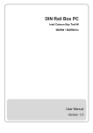
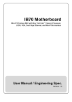
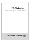
1
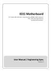
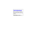
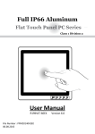
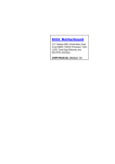
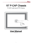
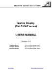
IB32 Motherboard 3.5” SBC with Intel ® Bay Trail Processors, HDMI, LVDS, VGA, Dual Giga Ethernet, and Mini- PCIe Interface User Manual / Engineering Spec. Version 1.2 IB32 Motherboard User Manual / Engineering Spec. FCC Statement This device complies with part 15 FCC rules. Operation is subject to the following two conditions: This device may not cause harmful interference. This device must accept any interference received including interference that may cause undesired operation. This equipment has been tested and found to comply with the limits for a class "a" digital device, pursuant to part 15 of the FCC rules. These limits are designed to provide reasonable protection against harmful interference when the equipment is operated in a commercial environment. This equipment generates, uses, and can radiate radio frequency energy and, if not installed and used in accordance with the instruction manual, may cause harmful interference to radio communications. Operation of this equipment in a residential area is likely to cause harmful interference in which case the user will be required to correct the interference at him own expense. Copyright Notice No part of this document may be reproduced, copied, translated, or transmitted in any form or by any means, electronic or mechanical, for any purpose, without the prior written permission of the original manufacturer. Trademark Acknowledgement Brand and product names are trademarks or registered trademarks of their respective owners. Disclaimer We reserve the right to make changes, without notice, to any product, including circuits and/or software described or contained in this manual in order to improve design and/or performance. We assume no responsibility or liability for the use of the described product(s), conveys no license or title under any patent, copyright, or masks work rights to these products, and makes no representations or warranties that these products are free from patent, copyright, or mask work right infringement, unless otherwise specified. Applications that are described in this manual are for illustration purposes only. Winmate Communication Inc. makes no representation or warranty that such application will be suitable for the specified use without further testing or modification. I IB32 Motherboard User Manual / Engineering Spec. Warranty We warrant that each of its products will be free from material and workmanship defects for a period of one year from the invoice date. If the customer discovers a defect, we will, at its option, repair or replace the defective product at no charge to the customer, provided it is returned during the warranty period of one year, with transportation charges prepaid. The returned product must be properly packaged in its original packaging to obtain warranty service. If the serial number and the product shipping data differ by over 30 days, the in-warranty service will be made according to the shipping date. In the serial numbers the third and fourth two digits give the year of manufacture, and the fifth digit means the month (e. g., with A for October, B for November and C for December). For example, the serial number 1W13Axxxxxxxx means October of year 2013. Packing List Before using this Motherboard, please make sure that all the items listed below are present in your package: IB32 Motherboard User Manual User’s Manual & Driver CD HDD SATA Cable If any of these items are missing or damaged, contact your distributor or sales representative immediately. Customer Service We provide service guide for any problem as follow steps: The first, contact with your distributor, sales representative, or our customer service center for technical support if you need additional assistance. You may have the following information ready before you call: Product serial number Peripheral attachments Software (OS, version, application software, etc.) Description of complete problem The exact wording of any error messages In addition, free technical support is available from our engineers every business day. We are always ready to give advice on application requirements or specific information on the installation and operation of any of our products. Please do not hesitate to call or e-mail us. II IB32 Motherboard User Manual / Engineering Spec. Safety Precautions Warning! Always completely disconnect the power cord from your chassis whenever you work with the hardware. Do not make connections while the power is on. Sensitive electronic components can be damaged by sudden power surges. Only experienced electronic personnel should open the PC chassis. Caution! Always ground yourself to remove any static charge before touching the CPU card. Modern electronic devices are very sensitive to static electric charges. As a safety precaution, use a grounding wrist strap at all times. Place all electronic components in a static-dissipative surface or static-shielded bag when they are not in the chassis. III IB32 Motherboard User Manual / Engineering Spec. Safety and Warranty 1. 2. 3. 4. 5. 6. 7. 8. 9. 10. 11. 12. 13. 14. 15. Please read these safety instructions carefully. Please keep this user's manual for later reference. Please disconnect this equipment from any AC outlet before cleaning. Do not use liquid or spray detergents for cleaning. Use a damp cloth. For pluggable equipment, the power outlet must be installed near the equipment and must be easily accessible. Keep this equipment away from humidity. Put this equipment on a reliable surface during installation. Dropping it or letting it fall could cause damage. The openings on the enclosure are for air convection. Protect the equipment from overheating. DO NOT COVER THE OPENING. Make sure the voltage of the power source is correct before connecting the equipment to the power outlet. Position the power cord so that people cannot step on it. Do not place anything over the power cord. All cautions and warnings on the equipment should be noted. If the equipment is not used for a long time, disconnect it from the power source to avoid damage by transient over-voltage. Never pour any liquid into an opening. This could cause fire or electrical shock. Never open the equipment. For safety reasons, only qualified service personnel should open the equipment. If any of the following situations arises, get the equipment checked by service personnel: A. The power cord or plug is damaged. B. Liquid has penetrated into the equipment. C. The equipment has been exposed to moisture. D. The equipment does not work well, or you cannot get it to work according to the user’s manual. E. The equipment has been dropped and damaged. F. The equipment has obvious signs of breakage. Do not leave this equipment in an uncontrolled environment where the storage temperature is below -20° C (-4°F) or above 60° C (140° F). It may damage the equipment. IV IB32 Motherboard User Manual / Engineering Spec. Revision History Version Date Note Author 1.0 2014.03.06 Initial Draft Marc Tsai 1.1 2014.08.15 Add Recovery Guide Jimmy Chen 1.2 2014.09.01 Add OS Selection Jimmy Chen V Contents CHAPTER 1: GENERAL INFORMATION ................................... 2 1.1 1.2 1.3 1.4 1.5 INTRODUCTION ...................................................................................... 2 FEATURE .............................................................................................. 2 MOTHERBOARD SPECIFICATIONS ............................................................ 3 FUNCTION BLOCK .................................................................................. 4 BOARD DIMENSIONS .............................................................................. 5 CHAPTER 2: INSTALLATIONS .................................................. 7 2.1 MEMORY MODULE (SO-DIMM) INSTALLATION ......................................... 7 2.2 2.3 2.4 2.5 I/O EQUIPMENT INSTALLATION ................................................................ 8 JUMPERS AND CONNECTORS .................................................................. 9 JUMPERS ............................................................................................ 10 CONNECTORS AND PIN ASSIGNMENT ..................................................... 14 CHAPTER 3: CHIPSET DRIVER INSTALLATION .................... 26 3.1 STANDARD CMOS FEATURES .............................................................. 26 CHAPTER 4: GRAPHIC DRIVER INSTALLATION ................... 30 4.1 4.2 STANDARD CMOS FEATURE ................................................................ 30 PANEL RESOLUTION SETTING ............................................................... 34 CHAPTER 5: ETHERNET DRIVER INSTALLATION ................ 37 5.1 INSTALLATION OF ETHERNET DRIVER..................................................... 37 CHAPTER 6: AUDIO DRIVER INSTALLATION ........................ 41 6.1 6.2 INTRODUCTION .................................................................................... 41 INSTALLATION OF AUDIO DRIVER ........................................................... 41 CHAPTER 7: FINTEK COM PORT DRIVER INSTALLATION .. 44 CHAPTER 8: AMI BIOS SETUP ............................................... 48 8.1 HOW AND W HEN TO USE BIOS SETUP .................................................. 48 8.2 8.3 BIOS FUNCTIONS ............................................................................... 49 USING RECOVERY W IZARD TO RESTORE COMPUTER ............................. 56 CHAPTER 9: APPENDIX .......................................................... 60 9.1 9.2 DIGITAL I/O SAMPLE CODE ................................................................... 60 WATCHDOG SAMPLE CODE .................................................................. 60 General Information CHAPTER IB32 Motherboard User Manual / Engineering Spec. 1 This chapter includes the IB32 Motherboard background information. Sections include: Introduction Feature Motherboard Specification Function Block Board Dimensions 1 IB32 Motherboard User Manual / Engineering Spec. Chapter 1: General Information 1.1 Introduction The IB32 SBC is integrated with Intel® Bay Trail-M Celeron N2930 which offers a high performance computing platform with low power consumption. The new motherboard supports 204-pin SO-DIMM DDR3L at speeds of 1333/1600 MHz, up to 8GB. One SATAII interface provides ample capacity. With dual Gigabit Ethernet, four COM ports, one USB 3.0 and five USB 2.0, IB32 SBC meet the requirements of today’s various applications. Display requirements are met with rich interfaces, such as HDMI, LVDS, and CRT. The graphic engine adopts Intel® SoC Integrated offer high definition display function, and it also supports 24-bit Dual-Channel LVDS. With all of the integrated features, IB32 SBC is designed to satisfy most of the applications in the industrial computer market, such as Gaming, POS, KIOSK, Industrial Automation, and Programmable Control System. It is a compact design to meet the demanding performance requirements of today’s business and industrial applications. 1.2 Feature 3.5-inch Form Factor (146mm x 102mm / 5.7 x 4 inches) Supports Intel® Bay Trail processors Intel® SoC Integrated 204-pin SO-DIMM DDR3L 1333/1600 MHz, up to 8GB Intel® HD Graphics Engine VGA, 18/24-bit Dual-Channel LVDS, 1 x HDMI 2 x Intel® WG82574L GbE 2 x Mini PCIe (one for wireless, one for mSATA SSD), 4 x COM, 1 x USB 3.0, 5 x USB 2.0, 1 x SATA II, 12-bit GPIO, 1 x 1394b DC 12V IN 2 IB32 Motherboard User Manual / Engineering Spec. 1.3 Motherboard Specifications Processor Intel® Celeron® Bay Trail-M N2930 1.83GHz Chipset BIOS Intel SoC Integrated AMI 64Mbit Flash Graphic LCD Interface Intel HD Graphics Engine Dual-channel 18/24 bit LVDS Up to 1920 x 1080 @ 60Hz VGA Mode : Up to 1600 x 1200 @ 60Hz HDMI : 1920 x 1080 @ 60Hz ® 2 x Giga LAN (Intel WG82574L GbE) 204-pin SO-DIMM DDR3L 1333/1600 MHz, up to 8GB Fintek F81866 Realtek ALC886 HD Audio Codec 1 x USB 3.0, 5 x USB 2.0 4 x COM ports Resolution LAN System Memory Super I/O Sound USB COM ® ® Edge Connectors 1 x DC-IN Power Jack (12V/19V) 1 x RS232/422/485 1 x USB 3.0, 1 x USB 2.0 1 x HDMI 2 x Gigabit LAN RJ-45 On Board Pin-Header Connectors 3 x RS-232 / 10-pin(2x5) 4 x USB 2.0 / 8-pin(2x4) 1 x LVDS / 40-pin(2x20) DF-13 connector 1 x SATA II 1 x SATA Power 1 x Digital I/O(12-bit GPIO) / 14-pin(2x7) 1 x Power-input / 2-pin 1 x +12V for external power(Yellow) / 2-pin 1 x +5V for external power(Red) / 2-pin 1 x +3.3V for external power(Blue) / 2-pin 1 x Fan / 3-pin 1 x Panel inverter / 7-pin 1 x Front panel / 10-pin(2x5) 1 x Backlight brightness controller / 3-pin 2 x Speaker with Amp. / 2-pin 1 x VGA / 10-pin(2x5) 1 x 1394b / 10-pin(2x5) (optional) 1 x Audio (Mic-in / Line-in / Line-out) / 12-pin(2x6) 1 x Battery / 2-pin Power Connector Expansion Slots 2-pin Power-input connector 1 x Mini PCIe for wireless, 1 x Mini PCIe for mSATA SSD Form Factor Dimensions 3.5 inch 146mm x 102mm Environmental Operating Temperature: -10~70°C (14~158°F) Operating Humidity: 10~90% Relative Humidity, non-condensing Shock: Operating 15G, 11ms duration Vibration: Operating 5 Hz~500Hz / 1Grms / 3 Axis Certification: CE, FCC, RoHS 3 IB32 Motherboard User Manual / Engineering Spec. 1.4 Function Block 4 IB32 Motherboard User Manual / Engineering Spec. 1.5 Board dimensions 5 CHAPTER IB32 Motherboard User Manual / Engineering Spec. Installations 2 This chapter provides information on how to use the jumps and connectors on the IB32 Motherboard. Sections include: Memory Module Installation I / O Equipment Installation Setting the Jumpers Connectors on IB32 Motherboard 6 IB32 Motherboard User Manual / Engineering Spec. Chapter 2: Installations 2.1 Memory Module (SO-DIMM) Installation The IB32 Motherboard provides one 204-pin SO-DIMM slot, and it supports up to 8GB DDR3L 1333/1600MHz. When installing the Memory device, please follow the steps below: Step.1. Firmly inserts the SO-DIMM at an angle into its slot. Align the SO-DIMM on the slot such that the notch on the SO-DIMM matches the break on the slot. Step.2. Press downwards on SO-DIMM until the retaining clips at both ends fully snap back in place and the SO-DIMM is properly seated. Caution! The SO-DIMM only fits in one correct orientation. It will cause permanent damage to the development board and the SO-DIMM if the SO-DIMM is forced into the slot at the incorrect orientation. 7 IB32 Motherboard User Manual / Engineering Spec. 2.2 I/O Equipment Installation 2.2.1 12V DC-IN The Motherboard allows plugging 12V DC-IN jack on the board without another power module converter under power consumption of Intel® Bay Trail-M Celeron N2930 Processor. 2.2.2 Serial COM ports One COM port connector which supports RS232/422/485 function by jumper setting has been built-in the rear I/O, and three internal COM ports can be connected to a serial or an optional touch-screen when an optional touch-screen is ordered with Panel PC. 2.2.3 External HDMI The Motherboard has one HDMI port that can be connected to an external LCD monitor by using HDMI cable, and it also needs to be connected to the outlet by power cable. The HDMI connector is a standard 19-pin Type A connector. 2.2.4 Ethernet interface The Motherboard is equipped with Intel® WG82574L GbE chipset which is fully compliant with the PCI 10/100/1000 Mbps Ethernet protocol compatible. It is supported by major network operating systems. The Ethernet ports provide two standard RJ-45 jacks. 2.2.5 USB ports Six USB devices (Four with pin headers) may be connected to the system though an adapter cable. Various adapters may come with USB ports. USB usually connect the external system to the system. The USB ports support hot plug-in connection. Whatever, you should install the device driver before you use the device. 8 IB32 Motherboard User Manual / Engineering Spec. 2.3 Jumpers and Connectors Component Side Solder Side 9 IB32 Motherboard User Manual / Engineering Spec. 2.4 Jumpers 2.4.1 Jumper List The following table lists the function of each of the board's jumpers. Label Function JP1 Inverter Voltage Select JP2 Inverter Enable Select JP4 DC Mode Control JP5 From SoC Brightness PWM Voltage Select JP6 Brightness Control Select JP7 Brightness Control to VRD JP8 COM Port Select JP9 COM Port Select JP10 VRD Brightness Function Note 3x1 header 2.0mm 3x1 header 2.0mm 3x1 header 2.0mm 3x1 header 2.0mm 3x1 header 2.0mm 3x1 header 2.0mm 2x3 header 2.0mm 3x4 header 2.0mm 3x1 header 2.0mm , pitch , pitch , pitch , pitch , pitch , pitch , pitch , pitch , pitch 2.4.2 Jumper Settings A metal-bridge jumper used to close an electric circuit, and it usually consists of two metal pins and one small clip protected by a plastic cover that slides over the pins to connect them. Users can connect the pins with the clip to close a jumper, and remove the clip to open a jumper. Generally, a jumper will have three pins which labeled 1, 2, and 3. In this case, you would connect either pins 1 and 2, or 2 and 3. The jumper setting diagram is as below. If a jumper shorts pin 1 and pin 2, the setting diagram is shown as the right one. 1 2 3 A pair of needle-nose pliers may be helpful when working with jumpers. If you have any doubts about the best hardware configuration for your application, contact your local distributor or sales representative before you make any changes. 10 IB32 Motherboard User Manual / Engineering Spec. JP1: Inverter Voltage Select JP2: Inverter Enable Select JP4: DC Mode Control JP5: From SoC Brightness PWM Voltage Select JP6: Brightness Control Select 11 IB32 Motherboard User Manual / Engineering Spec. JP7: Brightness Control to VRD JP8/JP9: COM Port Select 12 IB32 Motherboard User Manual / Engineering Spec. JP10: VRD Brightness Function 13 IB32 Motherboard User Manual / Engineering Spec. 2.5 Connectors and Pin Assignment The table below lists the function of each of the board’s connectors. Label Function DC Jack 12V Power Input COM1 RS232/422/485 USB 1/2 USB 3.0/USB2.0 Ports HDMI 1 HDMI Connector LAN1 / 2 Intel® LAN Ports 1394b 1394b (optional) SPK 2W External Speaker Audio Line_in / Line_out / Mic_in VGA VGA Internal Wafer LVDS LVDS Port SATA II SATA 2.0 Port SATA Power SATA Power CPU Fan CPU Fan Front Panel System Function (Power / Reset) 3.3V 3.3V Output 5V 5V Output 12V 12V Output GPIO General Purpose I/O 12V DC Input 12V DC Power Input Wafer USB 3/4 USB 2.0 Wafer USB 5/6 USB 2.0 Wafer COM2 RS232 COM3 RS232 COM4 RS232 Mini PCIe Full / Half-Size Mini PCIe Mini Card Slot DDR3L SO-DIMM For mSATA SSD Card DDR3L SO-DIMM Socket 14 IB32 Motherboard User Manual / Engineering Spec. 2.5.1 COM1: RS232/422/485 Pin No. SYMBOL Pin No. SYMBOL 1 DCD 2 RxD 3 TxD 4 DTR 5 GND 6 DSR 7 RTX 8 CTS 9 RI 2.5.2 USB 1/2: USB 3.0 (Lower)/USB2.0 (Upper)Ports Pin Number Signal Name Pin Number Signal Name 1 +5VUSB3.0 10 +5VUSB2.0 2 U2DN0 11 U2DN1 3 U2DP0 12 U2DP1 4 USB_GND 13 USB_GND 5 U3RXDN1 6 U3RXDP1 7 USB_GND 8 U3TXDN1 9 U3TXDP1 15 IB32 Motherboard User Manual / Engineering Spec. 2.5.3 HDMI: HDMI Connector Pin No. SYMBOL Pin No. SYMBOL 1 HDMIB_TMDS0+ 2 GND 3 HDMIB_TMDS0- 4 HDMIB_TMDS1+ 5 GND 6 HDMIB_TMDS1- 7 HDMIB_TMDS2+ 8 GND 9 HDMIB_TMDS2- 10 HDMIB_CLK+ 11 GND 12 HDMIB_CLK- 13 GND 14 NC 15 HDMI_DDC_CLK 16 HDMI_DDC_DATA 17 GND 18 +V5S 19 HDMI_HPD1 2.5.4 LAN1 (LAN2): Intel® LAN Ports (RJ-45) Pin No. SYMBOL Pin No. SYMBOL 1 MDI0_IN+ 2 MDI0_IN- 3 MDI1_IN+ 4 MDI1_IN- 5 VLAN_12 6 LAN1_DGND 7 MDI2_IN+ 8 MDI2_IN- 9 MDI3_IN+ 10 MDI3_IN- 11 LAN_VDD 12 LAN_TRAFFICLED# 13 LAN_SPD100LED# 14 LAN_SPD1000LED# 15 UGND 16 UGND 16 IB32 Motherboard User Manual / Engineering Spec. 2.5.5 1394b (optional) Pin No. SYMBOL Pin No. SYMBOL 1 1394b_TPB0+ 2 1394b_TPA0+ 3 1394b_TPB0- 4 1394b_TPA0- 5 GND 6 GND 7 +V12S 8 N/C 9 N/C 10 N/C 2.5.6 SPK: 2W External Speaker Pin No. 1 Pin No. 1 SYMBOL Pin No. LOUT+ SYMBOL 2 Pin No. ROUT+ 2 17 SYMBOL LOUT- SYMBOL ROUT- IB32 Motherboard User Manual / Engineering Spec. 2.5.7 Audio: Line_in / Line_out / Mic_in Pin No. SYMBOL Pin No. SYMBOL 1 AZ_FOUT_R 2 AZ_FOUT_L 3 +5VA 4 AUGND 5 LINE1_R 6 LINE1_L 7 MIC1_R 8 MIC1_L 9 AUGND 10 Font_SENSE 11 Mic_SENSE 12 Line_SENSE 2.5.8 VGA: VGA Internal Wafer Pin No. SYMBOL Pin No. SYMBOL 1 DAC_SDAT0 2 VGA_5V 3 DAC_SCL0 4 R_FILTER 5 3VHSYNC0 6 G_FILTER 7 3VVSYNC0 8 B_FILTER 9 GND 10 GND 18 IB32 Motherboard User Manual / Engineering Spec. 2.5.9 LVDS: LVDS Port Pin No. Pin No. SYMBOL 1 LCDVDD 2 TXOUT_L0- 3 LCDVDD 4 TXOUT_L0+ 5 LCDVDD 6 TXOUT_L1- 7 GND 8 TXOUT_L1+ 9 GND 10 TXOUT_L2- 11 GND 12 TXOUT_L2+ 13 GND 14 TXCLK_L- 15 GND 16 TXCLK_L+ 17 GND 18 TXOUT_L3- 19 GND 20 TXOUT_L3+ 21 GND 22 TXOUT_U0- 23 GND 24 TXOUT_U0+ 25 GND 26 TXOUT_U1- 27 GND 28 TXOUT_U1+ 29 GND 30 TXOUT_U2- 31 GND 32 TXOUT_U2+ 33 GND 34 TXCLK_U- 35 GND 36 TXCLK_U+ 37 GND 38 TXOUT_U3- 39 GND 40 TXOUT_U3+ Location CON5 SYMBOL Header Type Header 2*3 1 2 3 4 5 6 Description LVDS VOLTAGE 19 Function 3.3V 1-2 5V 3-4 12V 5-6 IB32 Motherboard User Manual / Engineering Spec. 2.5.10 SATA II: SATA 2.0 Port Pin No. SYMBOL Pin No. SYMBOL 1 GND 2 SATA_TXP 3 SATA_TXN 4 GND 5 SATA_RXN 6 SATA_RXP 7 GND Pin No. 2 SYMBOL +12V 2.5.11 SATA Power: Pin No. 1 SYMBOL +12V 3 GND 4 GND 5 GND 6 GND 7 VCC 8 VCC Pin No. 2 SYMBOL +12V 2.5.12 CPU Fan: Pin No. 1 SYMBOL GND 3 SENSE 20 IB32 Motherboard User Manual / Engineering Spec. 2.5.13 Front Panel: System Function (Power / Reset) Pin Signal Name Pin Signal Name 1 +V5S 2 +V3.3S 3 GND 4 -HDD_LED 5 PWRBTN# 6 GND 7 GND 8 PWRBTN# 9 N/C 10 +V5A 2.5.14 3.3V (5V / 12V): Power Output Pin No. SYMBOL Pin No. SYMBOL 1 VCC 2 GND 21 IB32 Motherboard User Manual / Engineering Spec. 2.5.15 GPIO: General Purpose I/O Pin No. SYMBOL Pin No. SYMBOL 1 GND 2 +V5A 3 DOUT3 4 DOUT1 5 DOUT2 6 DOUT0 7 DINT3 8 DINT2 9 DINT1 10 DINT0 11 GPIO53_IN0 12 GPIO56_OUT0 13 GPIO54_IN1 14 GPIO57_OUT1 2.5.16 12V DC Input: 12V DC Power Input Wafer Pin No. 1 SYMBOL +12V Pin No. 2 SYMBOL GND 2.5.17 USB 3/4 (USB 5/6): USB 2.0 Wafer Pin No. 1 SYMBOL VCC Pin No. 2 SYMBOL VCC 3 DATA0- 4 DATA1- 5 DATA0+ 6 DATA1+ 7 GND 8 GND 22 IB32 Motherboard User Manual / Engineering Spec. 2.5.18 COM2 (COM3 / COM4): RS232 Pin Signal Name Pin Signal Name 1 FK_NDCD[2:4] 2 FK_NDSR[2:4] 3 FK_NSIN[2:4] 4 FK_NRTS[2:4] 5 FK_NSOUT[2:4] 6 FK_NCTS[2:4] 7 FK_NDTR[2:4] 8 FK_NRI[2:4] 9 GND 10 GND 23 IB32 Motherboard User Manual / Engineering Spec. 2.5.19 Mini PCIe: Full / Half-Size Mini PCIe Pin No. SYMBOL Pin No. 2 VCC3_MINIPCIE1 1 PCIE_WAKE# 4 GND 3 NA 6 +V1.5S 5 NA 8 VREG_USIM 7 CLK_SLOT4_OE# 10 NA 9 GND 12 NA 11 CLK_PCIE_SLOT4_N 14 NA 13 CLK_PCIE_SLOT4_P 16 NA 15 GND 18 GND 17 NA 20 WLAN-RFON2 19 NA 22 BUF_PLT_RST2# 21 GND 24 +V3.3A 23 PCIE_RXN3_SLOT4 26 GND 25 PCIE_RXP3_SLOT4 28 +V1.5S 27 GND 30 SMB_CLK 29 GND 32 SMB_DATA 31 PCIE_TXN3_SLOT4 34 GND 33 PCIE_TXP3_SLOT4 36 USB_PN5 35 GND 38 USB_PP5 37 GND 40 GND 39 VCC3_MINIPCIE1 42 NA 41 VCC3_MINIPCIE1 44 NA 43 GND 46 NA 45 NA 48 NA 47 NA 50 GND 49 NA 52 VCC3_MINIPCIE1 51 NA m2 GND m1 GND 24 SYMBOL Chipset Driver Installation This chapter offers information on the chipset software Installation utility Installation of Chipset Driver Further information 25 CHAPTER IB32 Motherboard User Manual / Engineering Spec. 3 IB32 Motherboard User Manual / Engineering Spec. Chapter 3: Chipset Driver Installation 3.1 Standard CMOS Features Step.1. Insert the CD that comes with the motherboard. Open the file document “Chipset Driver”. Step.2. Click on “infinst_auto.exe“ to install driver. 26 IB32 Motherboard User Manual / Engineering Spec. Step.3. Click on “Yes “ to agree License Step.4. Click on “Next“ to install driver. 27 IB32 Motherboard User Manual / Engineering Spec. Step.5. Click on “Next“ to install driver. Step.7. Click on “Yes, I want to restart this computer now“ to go on. 28 Graphic Driver Installation CHAPTER IB32 Motherboard User Manual / Engineering Spec. This chapter offers information on the chipset software Installation utility Installation of Graphic Driver Panel Resolution Setting 29 4 IB32 Motherboard User Manual / Engineering Spec. Chapter 4: Graphic Driver Installation 4.1 Standard CMOS Feature IB32 Motherboard is equipped with Intel SoC Integrated Device. The Intel Graphic Drivers should be installed first, and it will enable “Video Controller (VGA compatible). Follow the instructions below to complete the installation. You will quickly complete the installation. Step.1. Insert the CD that comes with the Motherboard. Open the file document “Graphic Driver “. Step.2. Click on “setup” to execute the setup. 30 IB32 Motherboard User Manual / Engineering Spec. Step.3. Click on “Next “ to install Driver. Step.4. Click on “Yes “ to agree License. 31 IB32 Motherboard User Manual / Engineering Spec. Step.5. Click on “Next “ to install Driver. Step.6. Click on “Next “ to install Driver. 32 IB32 Motherboard User Manual / Engineering Spec. Step.7. Click on “Yes, I want to restart this computer now“ to go on. 33 IB32 Motherboard User Manual / Engineering Spec. 4.2 Panel Resolution Setting Step.1. Right-click the desktop, and then click Properties. Step.2. In the Display Properties dialog box, click the Settings tab. Step.3. Click on “Monitor”. 34 IB32 Motherboard User Manual / Engineering Spec. Step.4. Click on “Hide modes that this monitor cannot display” to remove this option. Step.5. Click on “Setting”, then could choose 32bit color qualify. 35 Ethernet Driver Installation CHAPTER IB32 Motherboard User Manual / Engineering Spec. 5 This chapter offers information on the Ethernet software installation utility. Sections include: Introduction Installation of Ethernet Driver 36 IB32 Motherboard User Manual / Engineering Spec. Chapter 5: Ethernet Driver Installation 5.1 Installation of Ethernet Driver The Users must make sure which operating system you are using in the IB32 Motherboard before installing the Ethernet drivers. Follow the steps below to complete the installation of the Intel WG82574L Gigabit Ethernet controller LAN drivers. You will quickly complete the installation. Step.1. Right-click the desktop, and then click Properties. Step.2. In the Other device dialog box, click the Settings tab. 37 IB32 Motherboard User Manual / Engineering Spec. Step.3. Click on “Update Driver” to execute the setup. Step.4. Click on “Browse my computer for driver software“ to install driver. 38 IB32 Motherboard User Manual / Engineering Spec. Step.5. Choose the path to install driver. Step.6. Click on “Close“ and go on. 39 Audio Driver Installation CHAPTER IB32 Motherboard User Manual / Engineering Spec. 6 This chapter offers information on the Audio software installation utility. Sections include: Introduction Installation of Audio Driver 40 IB32 Motherboard User Manual / Engineering Spec. Chapter 6: Audio Driver Installation 6.1 Introduction The ALC886 series are high-performance 7.1+2 Channel High Definition Audio Codecs providing ten DAC channels that simultaneously support 7.1 sound playback, plus 2 channels of independent stereo sound output (multiple streaming) through the front panel stereo outputs. The series integrates two stereo ADCs that can support a stereo microphone, and feature Acoustic Echo Cancellation (AEC), Beam Forming (BF), and Noise Suppression (NS) technology. 6.2 Installation of Audio Driver The users must make sure which operating system you are using in the IB32 Motherboard before installing the Audio drivers. Follow the steps below to complete the installation of the Realtek ALC886 Audio drivers. You will quickly complete the installation. Step.1. Insert the CD that comes with the motherboard. Open the file document “alc655_driver” and click on “Vista_Win7_R260.exe” to execute the setup. 41 IB32 Motherboard User Manual / Engineering Spec. Step.2. Click on “Yes“ to install driver. Step.3. Click on “Yes, I want to restart my computer now” to finish installation. 42 Fintek COM Port Driver Installation CHAPTER IB32 Motherboard User Manual / Engineering Spec. 7 This chapter describes the step by step method to install the Fintek COM port driver. 43 IB32 Motherboard User Manual / Engineering Spec. Chapter 7: Fintek COM Port Driver Installation Step.1. If the system is WIN7 please first do close UAC.(Refer following “Disabling User Account Control (UAC) in Windows 7”) Step.2. Extract the Patch_0408.zip to a folder. Step.3. Double-click batch file(patch.bat) will install driver. Step.4. Check driver install success. Before the update or update fail. After the update and update success. Step.5. You will need to restart your computer for driver install success. 44 IB32 Motherboard User Manual / Engineering Spec. Type in this command from the Run menu: C:\Windows\System32\UserAccountControlSettings.exe or uac 45 IB32 Motherboard User Manual / Engineering Spec. To turn off UAC, move the slider to the Never notify position, and then click OK. If you're prompted for an administrator password or confirmation, type the password or provide confirmation. To turn UAC back on, move the slider to choose when you want to be notified, and then click OK. If you're prompted for an administrator password or confirmation, type the password or provide confirmation. You will need to restart your computer for UAC to be turned off. 46 CHAPTER IB32 Motherboard User Manual / Engineering Spec. AMI BIOS Setup This chapter describes how to set up the BIOS configuration 47 8 IB32 Motherboard User Manual / Engineering Spec. Chapter 8: AMI BIOS SETUP 8.1 How and When to Use BIOS Setup For enter to the Tablet PC BIOS setup, you need to connect with an external USB keyboard, press “Del” key when the prompt appears on the screen during start up. The prompt screen shows only few seconds so need press Del key quickly. **NOTICE Updated BIOS version may be published after the manual is released. Check with the latest version of BIOS on website. You may need to run BIOS setup utility when the below status. 1. Error message on sreen indicate to check BIOS setup. 2. Restoring the factory default settings. 3. Modifing the specific hardware specification 4. Want to optimize the specification. In order to control the keyboard to select BIOS utility setup, you need Keyboard Icon Function Description Selects a menu title. Selects an item or option. Go to the sub-menu when available. Enter Opens or closes the option window when an item is selected. Esc To leave sub-menu and return to main menu. **NOTICE You can press the F1, F2, F3, F4, –/+, and Esc keys by connecting a USB keyboard to your tablet PC. 48 IB32 Motherboard User Manual / Engineering Spec. 8.2 BIOS Functions 8.2.1 Main Menu The Main menu contains the information of the Tablet system including BIOS version, processor RC version, system language, time, and date. 8.2.2 Advanced Menu The Advanced menu contains the selections of PXE OpROM and Watch Dog Timer, and the settings of PCI Subsystem, ACPI, and S5 RTC Wake. Besides, it also contains the configuration information of CPU, Thermal, IDE/SATA, USB, and PPM Configuration. 49 IB32 Motherboard User Manual / Engineering Spec. 1. CPU Configuration 2. Thermal Configuration 50 IB32 Motherboard User Manual / Engineering Spec. 3. IDE / SATA Configuration 4. USB Configuration 51 IB32 Motherboard User Manual / Engineering Spec. 5. PPM Configuration 6. OS Selection 52 IB32 Motherboard User Manual / Engineering Spec. 8.2.3 Chipset Menu The Chipset menu contains the information of North Bridge and South Bridge. 53 IB32 Motherboard User Manual / Engineering Spec. 8.2.4 Boot Menu The Boot menu sets the sequence of the devices to be searched for the operating system. The bootable devices will be automatically detected during POST and shown here, allowing you to set the sequence that the BIOS uses to look for a boot device from which to load the operating system. A brief description of button usage is listed next: 8.2.5 Security Menu In the Security menu, users can set Administrator Password, User Password, and HDD Security Configuration. 54 IB32 Motherboard User Manual / Engineering Spec. 8.2.6 Save & Exit Menu The Exit menu displays ways of exiting BIOS Setup utility. After finishing with your settings, you must save and exit so that the changes can take effect. Save Canges and Exit saves the changes you have made and exits BIOS Setup utility. Discarding Changes and Exit exits BIOS Setup utility without saving the changes you have made. Save Canges and Rest saves the changes you have made and resets BIOS system. Discarding Changes and Reset resets BIOS system without saving the changes you have made. Save Changes done so far to any of the setup options. Discard Changes done so far to any of the setup options. Restore Defaults loads/restore the factory default values for all the items. Save as User Defaults saves the changes one so far as User Defaults. Restore User Defaults loads/restore the User default values for all the items. 55 IB32 Motherboard User Manual / Engineering Spec. 8.3 Using Recovery Wizard to Restore Computer Bay Trail Intel® Celeron N2930 series computer has a dedicate recovery partition stored on the hard drive of the PC to enable quick one-key recovery process. This partition occupies about 11GB of the storage space, and comes built-in to each IB70 series PC. Warning: Before starting the recovery process, be sure to backup all user data, as all data will be lost after the recovery process. Follow the procedure below to enable quick one-key recovery procedure: Plug-in the AC adapter to Bay Trail series computer. Make sure the computer stays plugged in to power source during the recovery process. Turn on the computer, and when the boot screen shows up, press the F6 to initiate the Recovery Wizard. The following screen shows the Recovery Wizard. Click on “Recovery” button to continue. A warning message about data loss will show up. Make sure data is backed up before recovery, and click on “Yes” to continue. 56 IB32 Motherboard User Manual / Engineering Spec. Wait till the recovery process to complete. During the recovery process, a command prompt will show up to indicate the percent of recovery process. After recovery is completed, and the tablet computer will restart automatically. 57 IB32 Motherboard User Manual / Engineering Spec. Service / Update Official Website The relevant information about IB32 including the latest news and downloads will be presented in the website below: http://www.winmate.com.tw/BoxPc/EmbeddedSpec.asp?Prod=05_0156 Please go there to obtain further details of IB32 Motherboard. Company Information WinMate Communication INC. 9F, No.111-6, Shin- De Rd,. San- Chung City Taipei 241, Taiwan, R.O.C. Tel: 886-2-8511-0288 Fax: 886-2-8511-0211 Contact US: [email protected] Distributor and more Products (Please www.winmate.com.tw 58 refer to our website): CHAPTER IB32 Motherboard User Manual / Engineering Spec. Appendix This chapter includes appendix items for this user manual 59 9 IB32 Motherboard User Manual / Engineering Spec. Chapter 9: Appendix 9.1 Digital I/O Sample Code To find the Digital I/O Sample code, please refer to the IB32 driver CD SDK or contact us. 9.2 Watchdog Sample Code To find the Watchdog Sample code, please refer to the IB32 driver CD SDK or contact us. 60