1
NX241 DIGITAL TDcontroller
User Manual
Norms
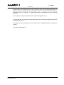
This equipment has been tested and found to comply with the following European and
international Standards for electromagnetic Compatibility and electrical Safety:
•
Electrical safety CEI65
•
Radiated emission EN55022
•
Conduction emissions EN55022
•
ESD tests: EN61000-4-2.
•
Immunity to fast electrical transients (sense input, RS232 link and AC inlet) EN61000-4-4
Safety Warning
This unit is fitted with 3-pin IEC standard power socket. For safety reasons the earth should not be
disconnected.
To prevent shock or fire hazard, do not expose the unit to rain or moisture.
To avoid electrical shock, do not remove covers. Dangerous voltages exist inside. Refer servicing
to qualified personnel only
PAGE 1/24
NEXO NX241 DIGITAL TDCONTROLLER
QUICK START
TABLE OF CONTENT
QUICK START
2
LIST OF SUPPORTED SET-UPS
3
GENERAL DESCRIPTION
4
FRONT PANEL
REAR PANEL
CONFIGURATION
EQUALISATION & FILTERING
DELAY & POLARITY INVERSION
AUDIO INPUT/OUTPUT
GENERAL FUNCTIONS
4
5
6
7
8
8
9
MENU - USER UTILITIES
11
MAIN FAMILY SELECTION
USER SETTINGS
SYSTEM SETTINGS
CONFIGURATION SELECT.
11
12
14
15
VOLTAGE SELECTION AND FUSES
16
PRECAUTIONS
POWER CONNECTION
115/230 SWITCHING
16
16
16
DOWNLOAD
17
WARNING
INSTRUCTION
17
18
PROTECTION INFORMATION NOTES
20
PROTECTION
20
SOME WORDS ON AMPLIFIERS
22
POWER
CURRENT RATING
AMPLIFIER GAINS
GAIN VALUE
ADVANCED PROTECTIONS
22
22
22
23
23
TECHNICAL SPECIFICATIONS
24
PAGE 2/24
QUICK START
Quick Start
•
This section contains a summary of most frequently asked questions by people who haven't
read the manual. You may be able to use the NX241 TDcontroller quite quickly as it has been
designed to be user friendly. However please devote some attention to reading this
manual. A better understanding of some specific features of the NX241 TDcontroller will
help you to operate your system to its full potential.
•
Please ensure that the unit is set for the correct mains input voltage BEFORE use.
•
WARNING: Information on the amplifiers used is MANDATORY. Before using your system
you MUST configure "MENU 2.6 AMP GAIN" and "MENU 2.7 AMP POWER". Failure to do so
or to properly connect the Sense Lines will invalidate the NEXO warranty on the attached
NEXO loudspeakers.
RESET
You can reset the unit without powering off by simultaneously depressing buttons A, B & SWAP
(!") at the same time.
Selecting cabinet family
Simultaneously depressing A & B buttons at A/C power up or during device RESET accesses the
system change menu. Keep the A & B Buttons until all LEDs light off. This will enable the
selection of any cabinet in any family. Using the rotary encoder, scroll through the configurations
and press ‘enter’ (!") to load the required settings.
Select your cabinet set-up
In MENU 3.0 you will be able to choose among the different set-ups within the same cabinet family.
(i.e. you don't have to modify the amplifier to cabinet wiring).
Navigating Menus
On the controller display screen, the number before the Function corresponds to the Menu
Number. To change the first number (this is the Main menu label) button A must be pressed. To
change the second number (this is the Submenu label) button B must be pressed. To select
options, turn the encoder wheel, or press the swap button (!"). Changes are immediate (no
validation is required unless clearly stated)
Back to default
In Menu 2.5 you have the possibility to put back all MENUS to the factory default (except the
amplifier information that you have entered (MENU 2.6 & 2.7)
Auto save
The current set-up is saved in case of power failure every two minutes after the last change. At
power up this set-up is restored
USER MANUAL LOAD1_80
DATE: 30/08/00 12:48
PAGE 3/24
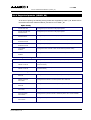
LIST OF SUPPORTED PRESETS (LOAD1_80)
List of Supported presets (LOAD1_80)
At the time of printing, the following factory presets are supported by LOAD 1_80. Please refer to
the release notes if the software loaded in your NX241 is not LOAD 1_80.
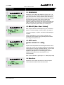
Alpha Family
ALPHATD B1+M3
Configured: Input A to drive a 3-Way Alpha System
ALPHATD S2+B1+M3
SubTD S2-63Hz
Configured: Input A to drive a 4-Way Alpha System
ALPHATD S2+B1+M3
SubTD S2-80Hz
Configured: Input A to drive a 4-Way Alpha System
ALPHATD S2+B1+M3
S2-63Hz AUX inB
Configures Input B (right) to drive the SUB channel independently
ALPHATD S2+B1+M3
S2-80Hz AUX inB
Configures Input B (right) to drive the SUB channel independently
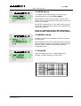
4 S2 cabinets
S2-63Hz
Configures all four channels to drive the S2 cabinet (crossover 63Hz)
4 S2 cabinets
S2-80Hz
Configures all four channels to drive the S2 cabinet (crossover 80Hz)
Alpha E Family
AlphaE STEREO
Configures 2 passive Alpha EM + 2 B1-18 (or 2 Alpha EF) in stereo
ALPHAE Mono
AEM B1-18 S2-63
Configures one passive Alpha Em with one B1-18 bass and one S2 Sub
(crossover 63Hz)
ALPHAE Mono
AEM B1-18 S2-80
Configures one passive Alpha Em with one B1-18 bass and one S2 Sub
(crossover 80Hz)
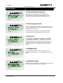
PS Family
PS8TD Wideband
NO SUB
Configures PS8 cabinet in wideband position (without sub)
PS8TD Crossover
With LS400
Configures PS8 cabinet in crossover position with LS400 sub
PS10TD Wideband
NO SUB
Configures PS10 cabinet in wideband position (without sub)
PS10TD Crossover
With LS500
Configures PS10 cabinet in crossover position with LS500 sub
PS15TD Overlap
With LS1200
Configures PS15 passive cabinet in wideband position with LS1200 available.
PS15TD Crossover
With LS1200
Configures PS15 passive cabinet in crossover position with LS1200 available.
USER MANUAL LOAD1_80
DATE: 30/08/00 12:48
USER MANUAL LOAD1_80
DATE: 30/08/00 12:48
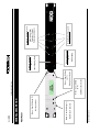
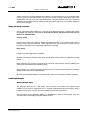
SUB Menu B selection
Menu - User Utilities
(p.11)
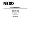
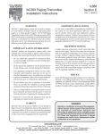
Swap Channels (!")
Main Menu A selection
!"
Menu - User Utilities
(p.11)
B
GENERAL DESCRIPTION
Menu - User Utilities (p.11)
A
Rotary encoder
Menu - User Utilities (p.11)
Front Panel
GENERAL DESCRIPTION
PAGE 4/24
DSP Clipping
Display & Indicators
(p.11)
Input Clipping (Red)
Display & Indicators
(p.11)
Mute/Solo buttons (p.11)
Peak limiting (Red)
Protection (Yellow)
Sense signal (Green)
Display & Indicators (p.11)
1
2
3
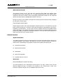
Fuse Type & Rating
USER MANUAL LOAD1_80
DATE: 30/08/00 12:48
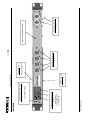
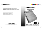
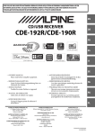
1/ IEC Socket
2/ Power ON/OFF
3/ Fuse Holder
Sense lines (p.9)
+ 4 - + 3 - + 2 - + 1 -
••••••••
SENSE INPUT
RS232
Download (p.17)
HIGH R
HF
4
LOW R
LF
LOW L
SUB
1
PAGE 5/24
Balanced Audio Output
(p.9)
HIGH L
MF
BALANCED OUTPUTS
3
2
RS232 Serial Port
GENERAL DESCRIPTION
Voltage selection and fuses
(p.16)
Voltage selection and fuses
(p.18)
Rear Panel
FUSES
Balanced Audio Input
(p.8)
LEFT
FULL RANGE
BALANCED INPUTS
RIGHT
AUX.SUB
Expansion Board Blank Panel
PAGE 6/24
GENERAL DESCRIPTION
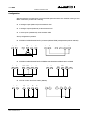
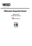
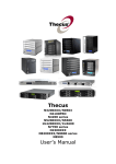
Configuration
Global architecture is based upon a full 24 bit audio path with 48-bit core calculator running at 100
Million Instructions per Second. Featuring:
n
2 analogue inputs (balanced) 24 bit resolution ADC
n
4 analogue outputs (balanced) 24 bit resolution DAC
n
4 sense inputs (unbalanced) 18 bit resolution ADC
Set-up configurations possible:
n
L
R
1
2
STEREO PASSIVE MODE WITH (or Without) MONO SUB (2 independent passive cabinets)
1
n
L
R
1
2
n
SUB
L
R
2
3
4
L
R
1
2
1
2
L
R
3
4
STEREO PASSIVE MODE WITH STEREO SUB & MONO PASSIVE WITH 2 SUBS
SUB L SUB R
1
2
L
R
L
R
3
4
1
2
SUB 1
1
SUB 2
MAIN
2
3
4
ACTIVE 4 WAY & ACTIVE 3WAY (MONO)
L
R
SUB
LF
MF
HF
1 L
2
1
2
3
4
USER MANUAL LOAD1_80
DATE: 30/08/00 12:48
L
R
SUB
LF
MF
HF
1 L
2
1
2
3
4
PAGE 7/24
GENERAL DESCRIPTION
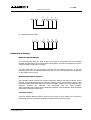
n
n
ACTIVE 3 WAY plus AUX SUB on INPUT B
L
R
SUB
LF
MF
HF
1
2
1
2
3
4
STEREO ACTIVE 2 WAY
L
R
1
2
LF L
1
LF R
HF L
HF R
2
3
4
Equalisation & Filtering
Subsonic and VHF filtering
Low and high-pass filters are used to filter out frequency components that could possibly
degrade the performance of the TDcontroller and amplifiers. The filters are optimised to work in
conjunction with overall system response.
The high pass filters are also extremely important as they optimise excursion at very low
frequency which is a very important safety factor. (So do not use set-ups which are not designed
for the cabinet you are using)
Equalising acoustical response
This equaliser section achieves the correction required to obtain a flat system response, as the
cabinets are acoustically designed for maximum efficiency on the whole frequency range. Active
rather than passive attenuation allows the lowering of amplifier voltages for a given output SPL and
therefore increases the maximum SPL achievable with the same amplifier.
Active equalisation also extends system bandpass especially at low frequencies where acoustical
performance is limited by cabinet size.
Crossover section
Crossover between different bands is tuned for every set-up of every cabinet. The crossover is
designed to ensure the best phase alignment possible over the crossover overlap.
USER MANUAL LOAD1_80
DATE: 30/08/00 12:48
PAGE 8/24
GENERAL DESCRIPTION
User set-up, Array EQ
A basic Array EQ is currently implanted in the NX241. The cut off frequency of a Low-shelving filter
is factory tuned for each cabinet setup. The user has access to the gain of this filter. Some more
sophisticated User EQ is currently under development. They will require the use of the upcoming
expansion board. Please read the readme.txt that comes along with every new software upgrade to
track eventual changes.
Delay & Polarity inversion
Input to output delay without filtering is 1.4ms (due to the digital processing). This delay will prevent
compatibility with analogue TDcontrollers. ANALOGUE AND DIGITAL TDCONTROLLER SHOULD NOT BE
MIXED IN THE SAME SYSTEM.
Factory set-up
Note that each output may contain a small phase adjustment delay at the crossover point. Also, a
polarity inversion may be performed. These adjustments are part of the factory set-ups and are
necessary to time-align the corresponding cabinet that is selected.
User set-up
Following user delay adjustment is possible:
GLOBAL: Affecting all channels at the same time (delaying all the system for application as delay
towers…)
MAIN: Affecting only CH3&4 for passive set-up and CH2, 3&4 for active channels (delaying the
main system if Sub basses are located behind it)
SUB: Affecting only CH1&2 for passive set-up and CH1 for active setup (delaying the Sub-bass
cabinet if main system are located behind it)
GLOBAL and MAIN/SUB delays are cumulative up to 150m per channel (about 450ms, 500 feet).
Audio Input/Output
Balanced Audio Input
The analogue inputs are on 3 pin female XLR connectors with positive and negative signal
polarities on pins 2 and 3 respectively. Pin 1 is coupled at high frequencies to the chassis using a
capacitor to limit screen currents, and to the analogue ground with a jumper link.
The input signal can be adjusted in MENU 1.1 HEADROOM in order to avoid clipping of the A/D
converter. See corresponding paragraph (MENU section)
USER MANUAL LOAD1_80
DATE: 30/08/00 12:48
PAGE 9/24
GENERAL DESCRIPTION
Balanced Audio Output
The analogue outputs are on 3-pin male XLR connectors with positive and negative signal
polarities on pins 2 and 3 respectively. Pin 1 is coupled at high frequencies to the chassis using a
capacitor to limit screen currents, and to the analogue ground with a jumper link. The output will
deliver a full-scale output of +28dBu(balanced 600Ω / 1nF load.)
During A/C power up of the NX241, all outputs are muted by firmware-controlled relays (strapping
pin 2 and pin 3 of each output).
Connecting the audio outputs
Output stages are able to drive several amplifiers in parallel; however it is not advised to work with
loads of less than 600 Ohm. It is best to check with the impedance characteristics of the inputs supplied by the manufacturer - to check if the number of amplifier channels is acceptable. Where
precise information is not available (and taking 5 kΩ as the minimum expected value) then seven
channels in parallel per output is a conservative maximum. In the case where input impedance is
20kΩ it puts this value up to 30 amps channels
General Functions
System Protections
The following protection functions are performed. See "Protection Information Notes" page 20 for a
complete description. As the NX241 TDcontroller is common to all NEXO cabinets, see also the
release notes corresponding to each software revision for an update of the following list.
n
Temperature Protection
n
Displacement protection
n
Peak limiting
n
Interchannel regulation
n
Physiologic Dynamic Control
Sense lines
Recommendations for sense line wiring
The Input impedance of the TDcontroller’s Sense inputs is very high, current is thus very low
although voltages are high. It is therefore not necessary to use a special type of cable. If the
processor is placed in the amp rack an unshielded cable can be used.
USER MANUAL LOAD1_80
DATE: 30/08/00 12:48
PAGE 10/24
GENERAL DESCRIPTION
Amplifier gain evaluation
This is used to determine the actual gain of the amp, and adjust for possible temperature drift,
amplifier input potentiometer adjustment or failure of this amp. This value is then compared to the
user-supplied nominal value and used for the displacement and temperature protection.
Remote sense
Line input (–18dB less than the amplifier gain) is possible and allows performing remote sense. At
this time these functions need additional accessories currently under development.
Reset
Holding down the three menu buttons (A, B, !") simultaneously will reset the unit. Reset has the
same effect as powering on and off the unit. The unit will mute (hardware) for 5 seconds with all
LED’s on. The unit will then return to the last set-up automatically saved (every 2 minutes).
Resetting the unit from the front panel is useful to change the cabinet family without powering off
and on (Press the three buttons to reset then let go of the swap button to enter into MENU 0). In
that case you will have to keep the A & B Buttons until all LEDs light off. Note that to execute a
download you will have to physically turn the unit off and then back on. (See "Download" page 17.)
Mute/Solo buttons
Front panel, direct access. The Mute (or Solo) mode is selected in the user menu. Please note that
these MUTEs are soft mute and are therefore not operating output relays.
Display & Indicators
User control of all settings is via two menu scroll pushbuttons, an additional assignable pushbutton,
an assignable rotary encoder and a backlit 16*2 character display.
Three LED’s per channel for sense (green), peak limit (red) protects (yellow). Four dedicated LED’s
are situated alongside the associated MUTE/SOLO button.
Two LED’s to indicate input overload and signal clipping into the DSP.
Default screen will pop up after 2 minutes and display the current set-up.
Serial link / Downloader
The unit can be RS232 linked to any PC in order to download new versions of software using a
DOS compatible Downloader program. (See "Download" page 17.)
USER MANUAL LOAD1_80
DATE: 30/08/00 12:48
PAGE 11/24
MENU - USER UTILITIES
Menu - User Utilities
On the controller display screen, the number before the Function corresponds to the Menu
Number. To change the first number (this is the Main menu label) button A must be pressed. To
change the second number (this is the Submenu label) button B must be pressed. To select
options, turn the encoder wheel, or press the swap button (!"). Changes are immediate (no
validation is required unless clearly stated).
Please refer to the release notes issued with each new download to track eventual menu changes.
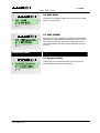
Main Family Selection
Changing Cabinet Family
In order to prevent end-user changing between different
NEXO system set-ups during use, the following procedure
is obligatory. This procedure has been purposely designed
to avoid any mistake. It is nevertheless very easy to change
set-up among the same family (see menu 3)
Simultaneously depressing A & B buttons at A/C power up
or a device reset accesses the system change menu. You
can reset the unit without powering off by simultaneously
depressing buttons A, B & SWAP (!") at the same time.
Note: Selecting a new family will set all parameters to
factory default settings.
USER MANUAL LOAD1_80
DATE: 30/08/00 12:48
PAGE 12/24
MENU - USER UTILITIES
User settings
1.1 HEADROOM
Allows the user to adjust the headroom (4 steps -6, 0, +6,
+12) before the A/D converter without changing the overall
gain of the processor. Factory default is set to maximum
headroom (and so, maximum noise). This can be adjusted
if you feel the processor is too noisy for lower level
applications. Adjust the Headroom while the unit is
operating making sure that the red Input Clip and DSP Clip
LED's never flash. The operation is sonically transparent
and will not generate glitches while you are doing so.
1.2 DELAYS [Sub / Main / Global]
Each output channel can be delayed by up to a maximum
(global + individual delay) of 450ms (150m). See page 8
The unit can display in [FEET / METRES / SECONDS] as
required.
Delay is adjustable in 10cm (0.3ms) increments. The
control pot will accelerate through the adjustments faster
according to the speed of use.
1.3 OUT Levels
[global / HF /MF / LF / SUB]]
Adjust overall & separate TDcontroller gain with this menu.
These gain controls are provided to adjust the tonal balance
of the system by acting on separate channels. You can also
compensate for gain differences between different
amplifiers. (Although the use of differing gain structure
amplifiers in the same set-up is possible it is not
recommended).
Each of the individual or global gain is +/- 6dB. (Step 0.5dB)
1.4 Mute/Solo
Allows the user to switch the function of the front panel
channel buttons between Mute and solo mode
USER MANUAL LOAD1_80
DATE: 30/08/00 12:48
PAGE 13/24
MENU - USER UTILITIES
1.5 SAVE Set-up
It is possible to store and recall up to 10 user set-ups
(including EARTH LIFT) but excluding MUTE.
Additionally the current set-up is saved in case of power
failure every two minutes after the last change. At power up
this set-up is restored.
Set-ups are numbered from 1 to 10. When saving your setup you can choose a reference name up to 6 characters for
identification purposes.
NOTE: ALL SAVED SETUPS WILL BE ERASED WHEN
DOWNLOADING A NEW VERSION OF THE SOFTWARE.
1.6 RECALL Set-up
Recalling a user set-up is forbidden if the family of cabinet
is not the same.
When recalling a set-up, the unit will stay in the recall menu
allowing another selection for comparison. Switching from a
set-up to another is glitch-free and instantaneous (no
muting takes place).
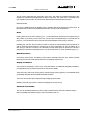
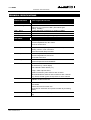
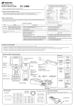
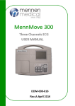
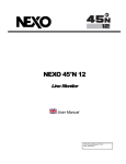
1.7 Array EQ
One array EQ gain control of +/- 6dB (0.5dB step) is
included. This filter frequency is factory tuned.
AlphaTD Controller Array EQ / Frequency (Hz) / Gain (dB)
10.000
8.0000
6.0000
4.0000
2.0000
0.0
-2.000
-4.000
-6.000
-8.000
-10.00
20
USER MANUAL LOAD1_80
DATE: 30/08/00 12:48
100
1k
10k
20k
PAGE 14/24
MENU - USER UTILITIES
System settings
2.1 Revision [soft & hard rev]
Displays the revision number of the LOAD; DSP
SOFTWARE; FLASH BOOT; HARDWARE. Turn the
encoder to access to the different revision screens.
2.2 Security [password]
The user password facility allows switching between "free
access", "unit locked" and "Change password. The factory
default password is NEXO.
This allows you also to get into an INSTALLER menu.
Please contact your NEXO dealer if access required.
2.3 Earth Lift
[CHASSIS LINKED / CHASSIS LIFTED]
Earth Lift information is stored in the "user set-up" and
"automatic save set-up". It will keep the same state when
powering the unit on or off (also in the event of mains
failure)
2.4 SENSE GAIN
Allows switching between line level sense lines and
amplifier level sense lines. (0 or 18dB gain on the sense
line)
2.5 DEFAULT VALS
Restores the factory defaults. System related values like the
AMP GAIN and AMP Power will not change.
USER MANUAL LOAD1_80
DATE: 30/08/00 12:48
PAGE 15/24
MENU - USER UTILITIES
2.6 AMP GAIN
Adjustable from 20dB to 40dB nominal Amp Gain in 0.5dB
steps for each channel.
2.7 AMP POWER
Allows you to enter a Nominal Amp RMS power into 8ohms.
Adjustable from 200 Watts to 5000 Watts in 50W steps for
each channel. Warning: this power is specified into an 8Ohm load and does not represent the maximum power of
the Amp.
Configuration select.
3.1 System Config.
Changing a set of parameters within the same family is
made immediately and is barely audible.
USER MANUAL LOAD1_80
DATE: 30/08/00 12:48
PAGE 16/24
VOLTAGE SELECTION AND FUSES
Voltage selection and fuses
Precautions
Please ensure that the unit is set for the correct voltage for your local supply BEFORE use.
Operating voltage is indicated in the window of the main socket at the rear of the unit.
Power connection
Connection is made by means of an IEC standard power socket. The unit will operate with AC
main voltage between 90Vac and 125Vac 50-60Hz in 115v mode and 180Vac to 264Vac 50-60Hz
in 230v mode.
Please note that each mode requires a different fuse. Before
connecting to the main AC supply, ensure that the fuse fitted is the
correct type (time-lag T, slow blow) and rating (115V/T400mA or
230V/T200mA), as indicated on the rear panel, adjacent to the fuse
holder.
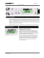
115/230 Switching
Voltage Selection Change requires no special tooling and can be performed in the field by
qualified service people.
DISCONNECT MAINS POWER TO THE UNIT, then follow these instructions:
•
Open the fuse holder window in the power entry module located on the rear of the unit.
(External access)
•
Remove the red fuse holder and insert the
corresponding fuse (115V/T400mA 230V/T200mA) for the voltage required into the
opposite side of the holder.
APPLY FORCE ONLY TO THE SHOULDERS, NOT
TO THE CONTACT FINGER IN THE MIDDLE.
CONVERSION CLIP
•
For safety reasons, when the fuse holder is
flipped around for voltage changing, the
conversion clip (small metal contact) should be
re-installed to the other side of the fuse holder.
Otherwise the fuse holder will not go back into the
housing completely and the power entry module
will not function.
The proper location of the conversion clip can be
checked in the following way. It should be located
to the left-hand side of the voltage number
selected, i.e., with the voltage label upright. See
diagrams opposite.
VOLTAGE SELECTION
PROPER CLIP LOCATION
•
Re-insert the red fuse holder, the required voltage
figure can now be seen in the fuseholder window.
•
The unit is now ready for use.
USER MANUAL LOAD1_80
DATE: 30/08/00 14:38
PAGE 17/24
DOWNLOAD
Download
Information concerning downloading in this manual are general instructions. Please read
the specific instructions that come with each new LOAD (readme.txt) file.
Warning
The latest version of the downloader program (NXLoad.exe) provided with each upgrade set of
files must ALWAYS be used.
A "NULL MODEM" or "LAPLINK" cable is required to connect your PC RS232 serial port to the
NX241 RS232 serial port.
Connection from NX241 RS232 9-Pin Serial Port to PC’s COM port
NX241 RS232 serial port
PC COM port
1
Don’t care
1
2 RXD
ß---------Receive---------
3
3 TXD
-----------Transmit-------à
2
4
Don’t care
6
5 SGND
Signal ground
5
6
Don’t care
4
7
Don’t care
8
8
Don’t care
7
9
Don’t care
9
The NEXO download software is DOS compatible and has been tested on the following operating
systems:
n
Microsoft MSDOS (V5.0 and above)
n
DOS shell of Microsoft Windows 3.x
n
DOS shell of Microsoft Windows 95
n
DOS shell of Microsoft Windows 98
n
Macintosh DOS compatible shell.
Note:
Due to the way Microsoft Windows NT addresses serial ports, the software does not currently run
on any version of Windows NT DOS shell. If you wish to use a machine that is running NT you will
have to make a bootable DOS disk, copy the downloader (NXLOAD.EXE) and the corresponding
USER MANUAL LOAD1_80
DATE: 30/08/00 12:48
PAGE 18/24
DOWNLOAD
LOAD (*.DLD) files to the disk and restart your machine in true DOS using this disk. [If you have
true DOS, to create a bootable disk under true DOS type the following "Format a: /s"]
Instruction
The files needed to execute your download will be provided as a *.ZIP file. You will have to extract
the content of this ZIP in a temporary directory using programs as Pkunzip or WINZIP (not provided
by NEXO). Once extracted you should have access to the following files:
•
Two download (.DLD) files: the last official release version and the newly released version. If
you experience any problems with the new version, simply load back the old .DLD program to
return the unit to the previous version.
•
A README.TXT that will contain download instruction
•
WHATSNEW.TXT, which will inform you with all new features of the new LOAD.
•
The downloader program NXLOAD.EXE
Execute the following procedure to load the new software into the NX241 Flash EPROM.
1) Connect the serial cable to both computer and NX241.
2) Execute your DOS shell (or start your machine from DOS).
3) At the DOS prompt, type the start command for the loader in the directory containing the files.
The correct syntax is as follows:
NXLOAD filename -COMport_number. <ENTER>
(e.g. NXLOAD LOAD1_80.DLD –1)
The downloader works with Com Ports 1 and 2 only. Com 3 and 4 cannot be used.
4) When you press <Enter> to invoke the command the following message appears on the
computer screen:
"Loading file...Waiting for NX241..."
Note: If the message is followed by a string of strange characters it is possible you have entered
the incorrect Com Port number. Hit ESCAPE to abort the procedure and start again. If nothing
happens, make sure that the cable is correctly wired and your computer COM port actually DOES
work before trying again. You can also try re-booting your machine.
5) Now to complete the procedure, you must set the NX241 to "Download" mode to make it ready
to accept the program.
USER MANUAL LOAD1_80
DATE: 30/08/00 12:48
PAGE 19/24
DOWNLOAD
Power the TDcontroller OFF and then back on whilst holding down the MUTE button of channel 1
(leftmost mute). The controller will now enter "Download " mode and the download will start. The
address of the code being loaded will be displayed on both the computer screen and the NX241
whilst the process is in operation. The download procedure is complete when the unit resets (all
LED's on).
6) The NX241 now HAS to be reset AGAIN to enter the configuration menu.
Turn the unit OFF, wait 5 seconds and then power back ON or hold down simultaneously the three
menu buttons (A, B, !").
Hold down the two menu buttons (A, B) to enter into the Configuration Menu to choose your
cabinet.
The unit is now ready for use.
USER MANUAL LOAD1_80
DATE: 30/08/00 12:48
PAGE 20/24
PROTECTION INFORMATION NOTES
Protection Information Notes
Protection
VCAs and VCEQs
Each channel has its own simulation and protection process.
Each audio channel contains a combination of controlled gain stages (let's call them VCA’s as in
our analogue circuitry). These VCA's are embedded into complex composite structures in order to
change their basic operation into frequency selective attenuation. This operation is similar to that of
a voltage controlled dynamic equaliser (VCEQ).
Each VCEQ and VCA is controlled by the synthesis of several signals issued from the various
detection sections. That synthesis is in fact the envelope of those signals, with an optimised release
and attack time for each VCEQ and VCA (depending on its frequency range and the cabinet
selected).
Displacement control
The Sense input signal is sent to a shaping filter producing a signal whose instantaneous amplitude
is proportional to the voice coil excursion. This signal, after rectification, is compared to a preset
threshold matching the maximum usable value, as determined from laboratory measurements.
Any part of the signal exceeding the threshold is sent to the VCEQ control buffer while the VCEQ
acts as an instantaneous limiter (very short attack time) to prevent displacement from overriding
the maximum permissible value.
Temperature control
Each sense signal is fed into a shaping filter (one per transducer), each one producing a signal
proportional to the instantaneous current flowing into the voice coil of the transducer. After
rectification, this signal is integrated with attack and release time constants equivalent to the
thermal time constants of the voice coil and chassis, producing a voltage, which is representative of
the instantaneous temperature of the voice coil.
When this voltage reaches the threshold value corresponding to the maximum safe operation
temperature, the VCA becomes active to reduce the Audio signal level and limit the effective
temperature to fall under the maximum usable value.
In order to avoid detrimental effects induced by very long release time constants coming from the
temperature detection signal (level being reduced for an extended period, « pumping » effects...),
the detection signal is modulated by another voltage integrated with faster time constants matching
the sound level subjective perception. This allows the controller to reduce the effective operation
duration of the temperature limiter and make it sound more natural, while the efficiency of
protection is fully preserved and operation thresholds are unaffected (kept as high as possible).
USER MANUAL LOAD1_80
DATE: 30/08/00 12:48
PAGE 21/24
PROTECTION INFORMATION NOTES
Physiologic Dynamic Control
The so-called Physiologic Dynamic Control is intended to avoid unwanted effects as a result of a
too long attack time constant. By anticipating the operation of the temperature limiter, it prevents a
high level Audio signal appearing suddenly then being kept up for a period, which is long enough to
trigger the temperature limiter. Without this, a rough and delayed gain variation would result which
would be quite noticeable and unnatural.
The Physio control voltage acts independently on the VCA with its operation threshold slightly
above (3 dB) that of the temperature limiter and a low compression ratio; its optimised attack time
constant allows it to start operating without any subjectively unpleasant transient effects.
Interchannel regulation
As described before, each transducer is individually servo-controlled for temperature.
This means in practice that, in case of a potential risk detected, protective operation would only
affect the concerned driver. Your driver will be protected but the overall system tonal balance could
be altered if the different channels are not heating at the same time. In addition, triggering a
temperature protection means that the loudspeaker has already lost some efficiency (power
compression up to 3dB in extreme cases)
The purpose of interchannel regulation is to cancel that effect by linking VCAs together. When the
protection is activated on one channel and reaches a predetermined threshold, the regulation
section begins to correct the balance between the different channels (HF, MF, and LF) by acting on
the concerned VCA.
Peak limiter
The peak limiter primary function is to avoid massive clipping of the amp, which can have some
very audible artefacts and in some cases may be dangerous for the Cabinets. (Modulation of the
amplifier’s rails can create very low frequencies not filtered at all by the NX241 or some harmonics
at high frequency and level…)
The threshold of the peak limiter is determined by the user to match its amplifier. (3 MENU AMP
POWER and AMP GAIN).
The second function of the peak limiter is to avoid huge amounts of power being sent to a driver.
Each driver is protected in temperature and displacement but there could be other factors of
destruction that cannot be predicted by simulation (especially mechanical damage to the cone…).
Each driver is specified for a certain power handling and a factory set peak limiter threshold is
tuned to avoid any abuse.
USER MANUAL LOAD1_80
DATE: 30/08/00 12:48
PAGE 22/24
SOME WORDS ON AMPLIFIERS
Some words on Amplifiers
Power
NEXO recommends high power amplifiers in all cases. Budget constraints are the only reason to
select lower power amplifiers. If an incident occurs on an installation without protection the fact that
amps only generating half their rated output power (-3dB) are used will not change anything in
respect of possible damage. This is due to the fact that the RMS power handling of the weakest
component in the system is always 6 to 10 dB lower than the amps' ratings.
Current rating
It is very important that the amplifier behaves correctly under low load conditions. A speaker system
is reactive by nature, on transient signals like music it will require much higher instantaneous
current than its nominal impedance would indicate (four to ten times more). Amplifiers are always
specified by continuous RMS power into resistive loads (which is irrelevant); the only useful
information in that respect is the specification into a 2 ohms load. It is possible to make an amplifier
listening test by loading them with twice the number of cabinets considered for the application (2
speakers per channel instead of one, 4 instead of 2…) and modulating at high level (onset of
clipping). If the signal does not noticeably deteriorate the amplifier is well adapted (overheating after
approximately ten minutes is normal but thermal protection must not operate too quickly after
starting this test).
Amplifier gains
As you already read in the Quick Start section Information on the amplifiers used is MANDATORY.
This value is the key of a correct setting. It is very important to know the gain of all amplifiers
present in your set-up. The tolerance shall be about ±0,5 dB. In practice this can be difficult to
achieve:
•
Some amplifier brands have an identical input sensitivity for models of different power rating (this
means DIFFERENT GAIN for each model). This problematic practice, inherited from non-professional
applications, is easily detected when the manufacturer specifies the same input sensitivity for all its
range (like 775mV/0dBm or 1.55V/+6dBm). This translates to very high gain values on higher power
models.
•
Other brands do offer constant gain but only within a given product range (like higher gain on all semiprofessional amps).
•
Even if a manufacturer is conscious of this problem and applies the constant gain rule to all its models,
the value he chooses is not necessarily the same as other manufacturers.
•
Some manufacturers can deliver products where manufacturing tolerance on the same model is ±1dB
or more. Worse, he can agree to modify this gain at the customer’s request without clear and visible
identification on the device. Some amps feature internal gain switches and it is sometimes impossible
to know the amp gain without measuring or opening it.
USER MANUAL LOAD1_80
DATE: 30/08/00 12:48
PAGE 23/24
SOME WORDS ON AMPLIFIERS
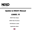
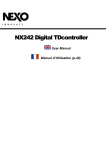
In cases where you don't know the gain of your amplifier (or want to check it) please read the
following instructions.
1. Unplug any cabinet from the amp
2. With a signal generator feed a sine wave (freq. within the audio range, 1000Hz for example)
Amplitude Vin is not important (1V is rather convenient). Unless if you use 0.7V sensitivity
where you will overflow the amp input!
3. Measure the Amplitude Volt at the output of the amp.
4. Gain = 20 * LOG10(Vout/Vin)
5. Some examples:
Gain
20dB
26dB
32dB
37dB (1.4V
sensitivity /
1350Wrms)
0.1V
1V
2V
4V
7.1V
0.5V
5V
10V
20V
35.4V
1V
10V
20V
40V
70.8V
Vin
Remember that constant sensitivity settings will give you different gain value when the amp Power
is different.
Gain value
NEXO recommends low gain amplifiers: +26dB is recommended, as it is at the same time
adequately low and quite common. This considerably improves signal to noise ratio and allows all
preceding electronic gear, including the TDcontroller, to operate at optimum level. Remember that
using a high gain amplifier will proportionally raise the noise floor level by the same amount.
Advanced protections
Some high-end amplifiers may have some advanced functions like those found in the NX241
TDcontroller ("loudspeaker offset integration", "limiter", "compressor"...). These functions are not
well adapted to specific system requirements and may interfere with existing protection within the
TDcontroller. NEXO do not recommend using these functions with the NX241 TDcontroller
USER MANUAL LOAD1_80
DATE: 30/08/00 12:48
PAGE 24/24
TECHNICAL SPECIFICATIONS
TECHNICAL SPECIFICATIONS
SPECIFICATIONS
NX241 Digital TDcontroller
Output Level
+28 dBu Max. into 600 Ohms load
Dynamic Range
Channels 1 & 2 = 99 dBu
Channel 3 & 4 = typical 107 dBu. (Flat without gain
scaling: 101dBu)
THD + Noise
< 0.02% flat setup (max0.04% for Output 27.5dBu)
Latency time
1.4ms on a flat setup
Power Supply
115/230 Volts 50/60 Hz (operating range 90-125V & 180-264V)
FEATURES
Audio Inputs
2 Audio Inputs 24 bit converters
Electronically Balanced, 36 k Ohms.
2 XLR-3F Connectors.
Sense Inputs
4 Amplifier Sense Inputs (LF mono, MF/HF L&R)
Floating 150 kΩ. 18 bit converters
8 Pole Removable Strip Terminal.
Audio Outputs
4 Audio Outputs. 24 bit converters
Electronically balanced, 50 Ohms
4 XLR-3M connectors
Processing
24 bit data with 48-bit accumulator. 100MIPS
Optional Expansion Board 300MIPS
Front Panel
Menu A and Menu B buttons
16 characters by 2 lines display
Select Wheel & Enter button (!")
IN Clip – DSP Clip red LED’s
Speaker Protection yellow LED for each channel
Individual Mute/Solo buttons and red LED for each channel
Amp. Sense & Peak (green & red) LED’s for each channel
FLASH EPROM
Upgrade for software improvement, new cabinet set-ups
available on NEXO web site.
Rear Panel
115/230 V switch
Fuse holder
RS232 connector for serial com.
Empty slot for extension card (communication & processing
power)
Dimensions & Weight
1U 19" Rack - 230 mm (9") Depth.
4 kg
USER MANUAL LOAD1_80
DATE: 30/08/00 12:48
France
NEXO S.A.
154 Allée des Erables
ZAC de PARIS NORD II BP 50107
F-95950 ROISSY CDG CEDEX
Tel: +33 1 48 63 19 14
Fax: +33 1 48 63 24 61
Email: [email protected]
USA
UK
FAR EAST
NEXO USA Inc.
NEXO limited
NEXO Far East Ltd
2165 Francisco Blvd.
Suite E2
San Rafael CA 94901
Tel: +1 415 482 6600
Fax: +1 415 482 6110
Email: [email protected]
9 Lyon Road
Walton-on-Thames
Surrey KT12 3PU
Tel: +44 1932 886 007
Fax: +44 1932 886 008
Email: [email protected]
101 Lorong, 23 Geyland
#06-04 Prosper House
Singapore 388399
Tel: +65 742 5660
Fax: +65 742 8050
Email: [email protected]