1
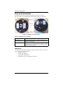
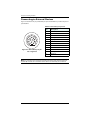
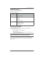
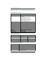
Chapter 2: Installing the A325
Connecting to External Devices
Figure 2-2 shows the 12-pin power/data port pinout and Table 2-3 provides the pinout
specifications.
Table 2-3: Power/data port pinouts
5
6
7
9
10
Description
1
Manual mark in
2
Port B Tx
3
Port B Rx
4
CAN high
3
5
Signal ground
2
6
Port A Tx
7
1 PPS
8
Port A Rx
4
11
12
8
Pin
1
Figure 2-2: Power/data port pinout assignment
9
CAN low
10
Power in (12 V)
11
Power ground
12
Speed out
Note: For successful communication, the baud rate of the A325 serial ports (Port A
and Port B) must be set to match that of the devices to which they are connected.
A325 GNSS Smart Antenna User Guide
12
PN 875-0318-000 Rev B1