1
Table of Figures
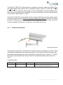
Figure.1.1 – ExCam IPQ1755 with wall mount bracket and roof ....................................... 6
Table 5.1 – Model key ..................................................................................................... 16
Figure 6.1 – ExCam IPQ1755 potential equalization ....................................................... 19
Table 6.1 – Potential equilization ..................................................................................... 19
Figure 6.2 – Cable gland and supply cable ..................................................................... 20
Figure 6.3 – ExCam IPQ1755 T08-VA2.2.K1.BOR-B-XXX-K-N ...................................... 20
Figure 6.4 – ExCam IPQ1755 T08-VA2.2.K1.BOR-B-XXX-P-N ...................................... 21
Figure 6.5 – ExCam IPQ1755 T08-VA2.2.K1.BOR-B-XXX-P(K)-L(L) ............................. 21
Table 6.2 – Pin assignment SKDxx and plug contact RJ45 ............................................. 22
Figure 6.6 – RJ45 Contact assignment ........................................................................... 23
Figure 6.7 – SKD01 Pin assignment ................................................................................ 23
Table 6.3 – Pin assignment supply cable ........................................................................ 24
Table 6.4 – Status and control LED ................................................................................. 25
Figure 6.8 – Zoom and focus of the ExCam IPQ1755 ..................................................... 25
Abb.6.9 – Advanced control functions of the ExCam IPQ1755........................................ 26
Table 6.5 – Lens data ...................................................................................................... 26
Figure 6.10 – Removing the protection roof_1................................................................. 28
Figure 6.11 – Removing the protection roof _2................................................................ 28
Figure 6.12 – Opening the ExCam IPQ1755 ................................................................... 29
Figure 6.13 – ExCam IPQ1755 installation components ................................................. 30
Figure 6.14 – SD card slot ............................................................................................... 30
Figure 6.15 – Control button ............................................................................................ 32
Figure 6.16 – Status display ............................................................................................ 32
Figure 7.1 – Axis IP Utility................................................................................................ 36
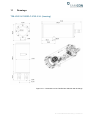
Figure.10.1 – Dimensions of the T08 ExCam IPQ1755 with K1 flange ........................... 39
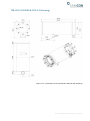
Figure 10.2 – Dimensions of the T08 ExCam IPQ1755 with K2 flange ........................... 40
Figure 10.3 – Dimensions of the T08 ExCam IPQ1755 accessories ............................... 41
Doc.-ID: 141023-PT08BA-TG-ExCam IPQ1755 series_en_rev.01, Seite 3 von 44