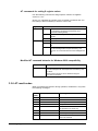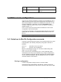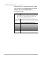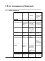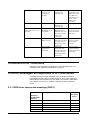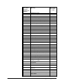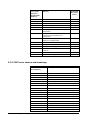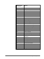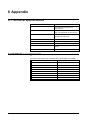
1
Bluetooth ISDN Terminal Adapter
BlueTA+
User manual
Version
Date
1.04
08.2002
Stollmann GmbH
Disclaimer
The content of this documentation is the intellectual property of
Stollmann. No reproduction, transmission, duplication or storage of this
documentation or parts thereof in a data storage and retrieval system, in
whatever form or in whatever manner, whether electronic, mechanical,
magnetic, or otherwise, is permitted without express prior written
approval by Stollmann. The information and technical data in this
documentation are subject to change without notice.
Stollmann does not assume any obligation to update any of the
information included herein.
Stollmann expressly disclaims any implied, express, or statutory
warranties, including, without limitation, the implied warranties of
merchantability, non-infringement of third-party rights or fitness for a
particular purpose.
Stollmann reserves the right to improve or make changes, in its sole
discretion, to the product(s) or software described herein.
Stollmann will not be liable for any damages, including, but not limited to,
loss of business, loss of profits, or loss of data, whether direct, indirect,
special, incidental, consequential, or punitive, related to or caused by the
delivery, use, or application of this documentation or the product
described herein.
© 2002 Stollmann GmbH
All rights reserved.
Content
1
Introduction
1.1
1.2
2
2.3
2.4
3
3.2
3.3
3.4
5
6
31
General error conditions.....................................................................................................31
Error messages as responses to AT commands..............................................................32
5.2.1 ISDN error causes and meanings (DSS1)............................................................32
5.2.2 CAPI error causes and meanings..........................................................................34
Appendix
6.1
6.2
29
Updating the BlueTA+ firmware.......................................................................................29
Updating the BlueTA+ firmware via Bluetooth.............................................................29
Updating the BlueTA+ firmware via ISDN.....................................................................30
Error messages and diagnosis
5.1
5.2
11
Configuring the BlueTA+ Bluetooth interface...............................................................11
3.1.1 Configuring using the BlueTA+Manager............................................................11
3.1.2 Configuring using a terminal emulation and AT commands...........................15
Configuring the BlueTA+ ISDN interface.......................................................................16
3.2.1 Configuring using the BlueTA+Manager............................................................16
3.2.2 Configuring using a terminal emulation and AT commands...........................18
AT commands ......................................................................................................................18
3.3.1 Local configuration (Bluetooth)...........................................................................18
3.3.2 Remote configuration (ISDN) ...............................................................................19
3.3.3 Guidelines for entering AT commands................................................................19
3.3.4 AT commands for Bluetooth.................................................................................20
3.3.5 AT commands for the ISDN interface .................................................................21
3.3.6 AT result codes ........................................................................................................26
ISDN remote configuration................................................................................................27
3.4.1 Guidelines for BlueTA+Configuration commands ...........................................27
3.4.2 BlueTA+Configuration commands......................................................................28
Firmware updates
4.1
4.2
4.3
8
Connecting the device...........................................................................................................8
Installing the software ...........................................................................................................8
2.2.1 Installing the software for Windows 98/ME.........................................................8
2.2.2 Installing the software for Windows 2000/XP......................................................9
Dial-Up Networking: New Data Transfer Device..........................................................10
2.3.1 Configuring new modem entries for existing Dial-up connections................10
2.3.2 New Dial-Up connection .......................................................................................10
Uninstalling the Software ...................................................................................................10
Configuring the BlueTA+
3.1
4
Product description................................................................................................................3
1.1.1 Prerequisites ...............................................................................................................3
1.1.2 Parts included.............................................................................................................4
1.1.3 Safety, License...........................................................................................................4
Working with the BlueTA+..................................................................................................5
1.2.1 Getting started............................................................................................................5
1.2.2 Establishing a Bluetooth connection to the BlueTA+.........................................5
1.2.3 LEDs and pushbutton ...............................................................................................6
Installation
2.1
2.2
3
36
Technical specifications .....................................................................................................36
ISDN Pin assignments ........................................................................................................36
7
Glossary
37
8
Index
41
Bluetooth ISDN Terminal Adapter BlueTA+
Content • i
ii • Content
Bluetooth ISDN Terminal Adapter BlueTA+
1 Introduction
1.1 Product description
BlueTA+ is a Bluetooth ISDN terminal adapter. It is used to connect a
Bluetooth terminal device — such as a PC — to an ISDN line. This allows
the terminal device to use ISDN services, e.g. in order to
•
Connect to the Internet
•
Connect to a remote LAN
•
Transfer data
When establishing Internet connections, the BlueTA+ supports the
following procedures and protocols:
•
Synchronous PPP or Multilink PPP
•
X.75 B-channel protocol
Which procedure/protocol is the correct one depends on the Internet
service provider or access point (point of presence or POP).
This documentation is valid for the BlueTA+
•
Hardware revision V2
•
Software versions V2.420 or later
What Is Bluetooth?
Bluetooth facilitates wireless communication between two devices over
short distances (up to approximately 10 meters/35 feet). Bluetooth
technology replaces connections normally used to connect devices such
as an ISDN terminal adapter and a PC. Bluetooth allows users to
dispense with cables, giving them more flexibility to position terminal
devices exactly where needed.
Once a Bluetooth radio link is established, Bluetooth activity is
transparent. This means that if, for example, you want to establish an
Internet connection to look up a page with your browser program, your
application works in exactly the same way it would if you were using a
conventional cable connection instead of Bluetooth.
1.1.1 Prerequisites
To use the BlueTA+ you need:
BlueTA+ 1.04/08.2002
•
An ISDN connection.
•
A Bluetooth-ready data terminal device such as a PC, notebook
computer or PDA with a Bluetooth adapter. The Bluetooth adapter
must support the Dial-Up networking profile (Bluetooth V1.1).
Introduction • 3
1.1.2 Parts included
The BlueTA+ comes with the following components:
•
1 BlueTA+ ISDN terminal adapter in a desktop housing
•
1 AC adapter for powering the BlueTA+
•
1 ISDN cable for connecting the BlueTA+ to an ISDN line
•
1 CD-ROM containing installation software for Windows
98/Me/2000/XP
•
1 user manual
1.1.3 Safety, License
The BlueTA+ is conform to the European safety requirements IEC 60
950. Please use only the delivered power supply or an original
replacement from Stollmann.
The BlueTA+ is conform to the European rules of EMC. EN55022 Class
B for electromagnetic field emission and EN55024 for immunity against
electromagnetic interference.
The BlueTA+ is conform to the Bluetooth standard V1.0b.
The BlueTA+ is conform to CCITT I.430 and ETSI TBR3/A1
4 • Introduction
1.04/08.2002 BlueTA+
1.2 Working with the BlueTA+
1.2.1 Getting started
To start using the BlueTA+ follow these steps:
1.
2.
3.
4.
5.
Connect the device: (a) to the ISDN line and (b) to a standard AC
outlet (see "Connecting the Device" on page 8.)
The yellow LED on the BlueTA+ front panel will stay flashing to
indicate that the device has been connected to an ISDN line.
Optionally: Install the software (see "Installing the Software" on
page 8). Start the Bluetooth control program of your Bluetooth
adapter (not included with the BlueTA+). Establish a Bluetooth radio
link to the BlueTA+ (see description at the bottom of this page).
Optionally: Configure the BlueTA+ Bluetooth interface if needed.
Configuration is required especially if you want to enable unrestricted
access to the BlueTA+. See "Configuring the BlueTA+ Bluetooth
interface" on page 11.
Optionally: If you want or need to use BlueTA+ ISDN settings other
than the factory settings, configure the ISDN interface. See
"Configuring the BlueTA+ ISDN interface" on page 16.
6.
If you are using BlueTA+ for the first time: Convert your existing dialup connections or define a new dial-up connection. See "Dial-Up
Networking: New Data Transfer Device" on page Fehler! Textmarke
nicht definiert..
Now you can work with all applications using an ISDN connection.
1.2.2 Establishing a Bluetooth connection to the BlueTA+
Start the Bluetooth control program of your Bluetooth adapter (not
included with the BlueTA+) and then proceed as follows:
1. Issue the Inquiry command to search for any Bluetooth devices.
If the search was successful: The control program will list the names
of the Bluetooth devices found. The BlueTA+ is factory preset with
the name "Stollmann BlueTA+".
2. Highlight this name, and select Dial-Up Networking from among the
services offered for this device.
3. Issue the command to establish a connection with this service using
a virtual COM port.
The green LED on the BlueTA+ front panel will come on to indicate that
the Bluetooth connection with the BlueTA+ has been established.
Note: If your application needs an ISDN connection, you must always
first establish the Bluetooth connection to the BlueTA+. This is also true if
you wish to configure the BlueTA+. To do so, start the control program for
your Bluetooth adapter. Then issue the command for establishing the
connection.
BlueTA+ 1.04/08.2002
Introduction • 5
1.2.3 LEDs and pushbutton
Push
Button
LED L1
Bluetooth
LED L2
ISDN
Two LEDs — green and yellow — on the BlueTA+ front panel indicate
the device’s operational and error status.
Any error status is indicated by
.
Green LED L1 for Bluetooth
Status after turning on the BlueTA+.
Fast Flashing
together with L2
(app. 4 seconds)
Blinking (50:50)
1 s cycle
BlueTA+ ready; no Bluetooth connection.
On
Bluetooth connection active.
Off
Device turned off (no power).
OR
BlueTA+ is not operational. Hardware error; repair
required.
Fast Flashing
while pressing
pushbutton
Press till flashing stops, to enter Log-on window.
Flashing (20:80, Log-on window open. A Bluetooth-enabled terminal device
max. 1 minute): may be registered for log-on slot n. See "Registering a
Pulse group with terminal device in the “Limited access”: " on page 13.
n pulses
Fast Flashing
together with L2
(continuously)
6 • Introduction
Boot loader active; no firmware present.
1.04/08.2002 BlueTA+
Yellow LED L2 for ISDN
Status after turning on the BlueTA+.
Fast Flashing
together with L1
(app. 4 seconds)
Blinking (50:50)
1 s cycle
BlueTA+ connected to ISDN (activated).
Off
Device turned off (no power).
OR
ISDN line deactivated.
On
BlueTA+ has established one or two ISDN connections.
Fast Flashing
together with L1
(continuously)
Boot loader active; no firmware present.
The pushbutton on the front panel lets you:
•
Restore the adapter to its factory default settings: Disconnect
device from power. Press pushbutton, turn on the device and
hold pushbutton pressed for at least 10 seconds.
OR
•
BlueTA+ 1.04/08.2002
Make the BlueTA+ ready for registering, when operating in
restricted mode. For more information, see "Configuring the
BlueTA+ Bluetooth Interface" on page 11.
Introduction • 7
2 Installation
2.1 Connecting the device
•
Use the ISDN connection cable (included) to connect the BlueTA+
ISDN port with your ISDN line (S 0 bus).
•
Connect the AC adapter (included) to the BlueTA+, and plug it into a
properly installed AC socket. The device is initialized and ready to
use.
The yellow LED on the BlueTA+ front panel will blink to indicate that the
device has been connected to an ISDN line.
2.2 Installing the software
For a Windows computer, you may install the software included with the
BlueTA+. The following items are installed on your data terminal device
(PC, notebook computer, etc.):
•
Device driver and Modem list
•
Configuration utility
Prerequisites
For your data terminal device you will need:
•
a fully configured Bluetooth adapter (not included)
•
a CD-ROM drive
•
Windows 98/ME/2000/XP as an operating system
•
The operating system installation CD (usually not required for
Windows ME/2000/XP).
2.2.1 Installing the software for Windows 98/ME
1.
2.
3.
4.
Insert the software disk in your disk drive.
Establish the Bluetooth connection with the BlueTA+. To do so, start
the control program of your Bluetooth adapter and issue the
command for establishing the connection. See page 5.
If the CD-ROM will not start automatically then please execute the
SETUP.EXE program on your disk. To do so, click Run... on the
Windows start menu. Click Browse , and change to CD-ROM drive
(usually D:\ or E:\). Double-click the icon for the SETUP.EXE file.
Then click OK.
Follow the instructions of the installation program. You may configure
the BlueTA+ either now or at some later point.
The following modems will be automatically installed:
- BlueTA+ X.75 (Win98,Me)
- BlueTA+ Internet PPP (Win98,Me)
- BlueTA+ Internet ML-PPP (Win98,Me)
Following software installation, you will find a new program folder called
BlueTA under Programs in the Windows start menu You may now use
the BlueTA+Manager to configure your BlueTA+ (see "Configuring using
the BlueTA+Manager on page 11).
8 • Installation
1.04/08.2002 BlueTA+
2.2.2 Installing the software for Windows 2000/XP
1.
2.
3.
4.
Insert the software disk in your disk drive.
Establish the Bluetooth connection with the BlueTA+. To do so, start
the control program of your Bluetooth adapter and issue the
command for establishing the connection. See page 5.
If the CD-ROM will not start automatically then please execute the
SETUP.EXE program on your disk. To do so, click Run... on the
Windows start menu. Click Browse , change to CD-ROM drive
(usually D:\ or E:\). Double-click the icon for the SETUP.EXE file.
Then click OK.
Follow the instructions of the installation program. You may configure
the BlueTA+ either now or at some later point.
The following modem will be automatically installed:
- BlueTA+ (Win2000,XP)
Following software installation, you will find a new program folder called
BlueTA under Programs in the Windows start menu. You may now use
the BlueTA+Manager utility to configure your BlueTA+ (see "Configuring
using the BlueTA+Manager on page 11).
BlueTA+ 1.04/08.2002
Installation • 9
2.3 Dial-Up Networking: New Data Transfer Device
2.3.1 Configuring new modem entries for existing Dial-up connections
Following installation of the driver software, a new device (modem) is
available on your system for all ISDN connections you have defined:
BlueTA+. To make existing connections use this device, proceed as
follows:
Double-click the Dial-Up Networking or Network and dial-upconnections icon. (You will usually find it in the My Computer folder or
in the Control Panel.) Dial-up connections already defined are each
indicated by their own icons. Right-click on an icon to open the
corresponding pop-up menu. Left-click on Properties to open the
Properties dialog. Select the BlueTA+ from Connect using... on the
General tab.
2.3.2 New Dial-Up connection
The data and settings of ISDN connections are stored on your computer
in the Dial-Up Networking or Network and dial-up-connections folder.
(You will usually find it in the My Computer folder or in the Control
Panel.) To define a new connection, e.g. to an Internet service provider,
you must create a new dial-up connection. To do so, you must know and
enter the appropriate connection data, which you can obtain from your
service provider. These data usually include:
•
Number to dial for the provider’s access point
•
Transfer protocol (usually Internet PPP for Internet connections)
•
User name
•
Password
Instructions on how to create a new dial-up connection to the Internet are
available in your Windows documentation. As a rule, you may simply
proceed as follows:
Double-click the Dial-Up Networking or Network and dial-upconnections icon. (You will usually find it in the My Computer folder or
in the Control Panel.) Double-click the Make new connection icon.
Follow the instructions on the screen. Select "BlueTA+" under Connect
using...
2.4 Uninstalling the Software
To uninstall the BlueTA+ Software from your computer, click the
Uninstall Stollmann BlueTA+ icon in the BlueTA+ program folder.
10 • Installation
1.04/08.2002 BlueTA+
3 Configuring the BlueTA+
3.1 Configuring the BlueTA+ Bluetooth interface
When configuring the BlueTA+ Bluetooth interface, you can restrict
BlueTA+ access to those Bluetooth-enabled terminal devices that are
specifically authorized by you.
You may configure the BlueTA+ as follows:
•
Using any terminal emulation program—such as
HyperTerminal (included with Windows)—by way of AT
commands
•
Using the BlueTA+ Management Application
(recommended), if your operating system is Windows and
you have the BlueTA+Manager installed.
3.1.1 Configuring using the BlueTA+Manager
First, establish a Bluetooth connection with the BlueTA+ (see page
Fehler! Textmarke nicht definiert.). Then start the BlueTA+Manager.
The BlueTA+Manager starts by reading the BlueTA+ configuration data.
This may take up to 5 seconds.
BlueTA+ 1.04/08.2002
Configuring the BlueTA+ • 11
Click the Bluetooth tab in case if not selected.
Edit the entries in the dialog (see explanations below). Then confirm your
settings by clicking OK.
Bluetooth tab of the BlueTA+ Manager
Security Modes
The BlueTA+: can be operated in 3 different Security Modes:
•
Free access: Every Bluetooth device with corresponding profiles
within the range of the BlueTA+ ( about 10 m, 35 feet) can get
access to ISDN. The user does not need to know the PIN nor to
have direct access to the BlueTA+. A registering is not necessary.
•
Limited access: Only those Bluetooth devices which are paired
with the BlueTA+, can get access to ISDN. To do the registering it
is necessary to know the PIN.
•
Restricted mode: This setting implies that any Bluetooth adapter
within a radius of approximately 10 meters/35 feet has to register
to the BlueTA+. To make the BlueTA+ ready for registering
please press the pushbutton. For registering the correct PIN code
is required.
The activated security mode is shown in the Bluetooth tab of the
BlueTA+ Manager.
12 • Configuring the BlueTA+
BlueTA+ 1.04/08.2002
Set PIN code
The PIN code by default is set to 0000.
To define a new PIN code, you must enter the old PIN code in the upper
fields and the new PIN code in the lower two fields.
Effect:
The Bluetooth connection is interrupted. From that point onward, only
those Bluetooth-enabled terminal devices can establish a Bluetooth
connection with the BlueTA+ that are registered with the BlueTA+ - see
below.
Registering a terminal device in the “Limited access”:
With limited access activated, only those Bluetooth-enabled terminal
devices can establish a Bluetooth connection with the BlueTA+ that are
registered with the BlueTA+, see below. To register a terminal device,
proceed as follows:
1. Use the terminal device to be registered to establish a Bluetooth
connection with the BlueTA+. To do so, start the Bluetooth adapter
control program on that device and issue the command for
establishing the connection—see page 5. When prompted to enter a
PIN code, enter the current BlueTA+ PIN code.
This completes the registration of this terminal device. The BlueTA+
creates a key from the device ID of the Bluetooth adapter of the
respective terminal device and the valid PIN code entered and stores it in
the open log-on slot. This will let the BlueTA+ know that terminal device
now has the right to access it.
Effect:
The log-on slot selected in Step 1 contains the access key for this
terminal device. The device can now establish a Bluetooth connection
with the BlueTA+.
If you would like to register another terminal device, simply repeat Step 1.
The key of the other terminal device will be stored automatically on the
next free log-on slot. If all log-on slots are occupied, the log-on slot will be
overwritten beginning with slot 1. You can register up to 10 different
Bluetooth-enabled terminal devices.
(Changing the PIN code after a device is registered does not invalidate
the registration for that terminal device.)
Registering a terminal device in the “Restricted mode”:
With restricted mode activated, only those Bluetooth-enabled terminal
devices can establish a Bluetooth connection with the BlueTA+ that are
registered with the BlueTA+, see below. To register a terminal device,
proceed as follows:
2. Press the pushbutton on the BlueTA+ front panel (the Bluetooth LED
will start flashing) till the Bluetooth LED stays on. This will open a
"registration window" for one minute.
3.
BlueTA+ 1.04/08.2002
Use the terminal device to be registered to establish a Bluetooth
connection with the BlueTA+. To do so, start the Bluetooth adapter
control program on that device and issue the command for
Configuring the BlueTA+ • 13
establishing the connection—see page 5. When prompted to enter a
PIN code, enter the current BlueTA+ PIN code.
This completes the registration of this terminal device. The BlueTA+
creates a key from the device ID of the Bluetooth adapter of the
respective terminal device and the valid PIN code entered and stores it in
the open log-on slot. This will let the BlueTA+ know that terminal device
now has the right to access it.
Effect:
The log-on slot selected in Step 1 contains the access key for this
terminal device. The device can now establish a Bluetooth connection
with the BlueTA+.
If you would like to register another terminal device, simply repeat Steps
1 and 2. In Step 1 the key of the other terminal device will be stored
automatically on the next free log-on slot. If all log-on slots are occupied,
the log-on slot will be overwritten beginning with slot 1. In Step 2, use the
other terminal device to be registered to establish a Bluetooth connection
with the BlueTA+.
You can register up to 10 different Bluetooth-enabled terminal devices.
(Changing the PIN code after a device is registered does not invalidate
the registration for that terminal device.)
Deleting Log-On slot values (access rights)
If you want to prevent a previously registered terminal device from further
accessing the BlueTA+, use the BlueTA+Manager (Bluetooth tab) to
issue the command to remove the registration for that particular log-on
slot.
Effect:
The terminal device whose access right was canceled from its log-on slot
can no longer establish a Bluetooth connection with the BlueTA+.
Changing device names
If you would like your BlueTA+ to appear in your Bluetooth control
program under a different device name, use the Bluetooth tab of the
BlueTA+Manager to enter the new name in the respective field.
Forgotten Pin Code: Restoring the Bluetooth interface to factory
defaults
To change the PIN code for Bluetooth access, you must know the current
PIN code. If you have forgotten the PIN code, the only thing you can do is
to reset the BlueTA+ to its factory default settings.
To restore the BlueTA+ to its factory default settings, proceed as follows:
1.
2.
3.
4.
Disconnect the BlueTA+ from its power source.
Press the pushbutton on the BlueTA+ front panel
Restore power to the device while keeping the pushbutton pressed
for at least 10 seconds.
When Bluetooth factory defaults will be set up the LEDs will stop
flashing.
Effect:
14 • Configuring the BlueTA+
•
The PIN code is reset to 0000.
•
The device name is reset to Stollmann BlueTA+.
BlueTA+ 1.04/08.2002
•
All log-on slots are evacuated. The security mode is switched to
default.
Note: Concurrent access of several terminal devices is not possible in an
of the security modes.
3.1.2 Configuring using a terminal emulation and AT commands
See "AT commands" on page 18.
BlueTA+ 1.04/08.2002
Configuring the BlueTA+ • 15
3.2 Configuring the BlueTA+ ISDN interface
By configuring the ISDN interface of the BlueTA+, you can determine the
behavior of the ISDN communication. The factory default settings should
be workable in almost all situations. If you do make changes to these
settings, make sure that the new settings agree with those required by
the remote system.
You may configure the BlueTA+ as follows:
•
Using the BlueTA+Manager (recommended), if your operating
system is Windows and you have the BlueTA+Manager installed.
•
Using any terminal emulation program – such as HyperTerminal
(included with Windows) – by way of AT commands. You can use AT
commands to change settings that cannot be accessed with the
BlueTA+Manager.
•
Remote configuration via an ISDN connection with your BlueTA+.
You have to set up an ISDN connection from an ISDN Terminal
Adapter by using a terminal emulation program.
3.2.1 Configuring using the BlueTA+Manager
Establish the Bluetooth connection with the BlueTA+. Then start the
BlueTA+Manager.
The BlueTA+Manager starts by reading the BlueTA+ configuration data.
This may take up to 5 seconds.
Most basic settings can be selected on the General Settings tab.
General Settings tab of the BlueTA+ Manager
16 • Configuring the BlueTA+
BlueTA+ 1.04/08.2002
Change the D-channel protocol only if you are planning to use the
BlueTA+ in a different telephone network with a different type of ISDN
implementation than E-DSS1.
Data Port tab of the BlueTA+ Manager
Call answering
On the Data Port tab of the BlueTA+Manager, you can determine what
incoming calls, if any, the BlueTA+ is to answer.
If the BlueTA+ is to answer only calls arriving for a specific MSN, select
the Accept incoming calls only for this MSN option and indicate the
MSN in the field below.
The setting Accept all incoming calls (default) causes the BlueTA+ to
answer all incoming data calls. Incoming voice or fax calls are passed
unhindered to other terminal devices—if connected—and can then be
answered by these devices (phone, fax machine, etc.).
Dynamic use of the second B channel (MLPPP channel bundling)
Activating the Bandwidth on Demand (BOD) option on the Data Port
tab of the BlueTA+Manager has the following effect:
In situations where large data volumes are to be transferred, the second
B channel of your ISDN line is automatically used so that twice as many
data per time unit can be transferred. Note the following details:
BlueTA+ 1.04/08.2002
Configuring the BlueTA+ • 17
-
-
The B channel is added automatically when the data stream
exceeds a certain threshold volume (Traffic) for a certain duration
(Time). This threshold volume can be set in “Increase”.
The B channel is dropped automatically when the data stream falls
below certain threshold volume (Traffic) for a certain duration
(Time).. This threshold volume can be set in ”Decrease”.
The Bandwidth on Demand function optimizes your ISDN line usage for
data transfers.
Only necessary using Windows95:
Passwords for CHAP and MSCHAP
Depending on the underlying authorization technology—CHAP or
MSCHAP—, the RAS password may have to be repeated during RAS
sessions for accessing the second B channel. In this case, please the AT
command AT**CHAP to setup the password (see page 18).
Options (available with a later release):
Answering calls while the second B channel is in use
Activating the Call bumping option on the Data Port tab of the
BlueTA+Manager has the following effect:
If both B channels are in use and the BlueTA+ recognizes an incoming
call for an MSN that is different from that of the BlueTA+, the BlueTA+
immediately relinquishes the second B channel used, freeing this channel
for a different device—such as a phone—answering the call.
Your ISDN provider must support the call bumping function for your line.
3.2.2 Configuring using a terminal emulation and AT commands
See "AT commands" on page 18.
3.3 AT commands
Use the AT commands (listed from page 20) to configure
•
the Bluetooth interface or
•
the ISDN interface
of the BlueTA+. The BlueTA+Manager for Windows is a user-friendly
configuration interface. However, you can use any terminal emulation
program (under Windows or other operating systems) to issue AT
commands for configuring the BlueTA+. You can also use AT commands
to change settings that cannot be accessed by the BlueTA+Manager.
3.3.1 Local configuration (Bluetooth)
First, establish a Bluetooth connection to the BlueTA+ (see page 5).
Start any terminal emulation program – such as HyperTerminal (included
with Windows).
18 • Configuring the BlueTA+
BlueTA+ 1.04/08.2002
If no connection with the BlueTA+ is defined in this terminal program, do
so now:
1. Select a direct connection via the virtual COM interface by which your
Bluetooth adapter is addressed.
2. Connection settings (transfer rate, data bits, parity, stop bits) are not
relevant and may have any setting.
Activate the connection with the BlueTA+ by entering “AT” and the
Return key.
Activate the desired settings by issuing the corresponding AT commands
(see below).
3.3.2 Remote configuration (ISDN)
You may use a remote computer to configure your local BlueTA+ via an
ISDN connection as long as the remote system also uses a BlueTA+ or
other terminal adapter by Stollmann to establish the connection. To dial
into the local BlueTA+, use the AT command AT<number>e (for
<number>, insert the ISDN number of your local BlueTA+ without the
angled brackets < >.)
The "e" at the end of the number tells the local BlueTA+ that remote
configuration is about to take place.
Any BlueTA+Configuration command (see below) issued by the remote
system after the connection is established will take effect for the local
BlueTA+.
Note: The X.75 (ATB10) protocol must be used for remote configuration.
3.3.3 Guidelines for entering AT commands
Type every command exactly as shown and then press the Return key.
The Return key is represented in the following examples by the graphic
character ↵.
Example:
ATB10 ↵
AT&W ↵
Switches to the protocol X.75
Saves the new configuration
The BlueTA+ acknowledges receipt of a command at ISDN settings with
either OK or an error message.
Every command (with the exception of A/) starts with AT, followed by one
or more parameters. Each command line can be up to 80 characters
long. Longer command lines are not accepted. Spaces are ignored.
Uppercase and lowercase letters can be used interchangeably. With the
Backspace key you can delete characters inside a command line.
If you wish to issue AT commands while an ISDN data connection is
active, you will first have to change to command mode:
Following a pause of at least one second, type +++ (three plus
characters). Do not press the Return key. Do not wait more than one
second between the + characters. Wait at least one second after the third
+ character.
The BlueTA+ will change to command mode and responds with OK.
The ATO command returns BlueTA+ to transfer mode.
BlueTA+ 1.04/08.2002
Configuring the BlueTA+ • 19
Storing a configuration
To store configuration settings, issue the command AT&W.
This will store the current setting in the BlueTA+ memory so they are
automatically reapplied even if the device is turned off and back on again.
3.3.4 AT commands for Bluetooth
In the following tables, factory default settings are indicated in boldface.
Items in angled brackets < > are to be replaced by the actual or desired
values or parameters. The angled brackets themselves are not entered.
Example: For <old_PIN_code> enter the old PIN code.
A detailed description of all possible settings is given under "Configuring
using the BlueTA+" on page 11.
Command
Explanation
AT**BPIN=<old_PIN-code>,<new_PIN_code>
Changes the PIN code. For <old_PIN_code>, enter the old pin code.
For <new_PIN_code>, enter the new pin code. The old PIN code
must be correct for the command to take effect.
The factory default Bluetooth PIN code is 0000, 4 digit number.
20 • Configuring the BlueTA+
AT**?BPIN
Displays help for Bluetooth PIN codes.
AT**BNAME
Displays the device name.
AT**BNAME=<na
me>
Defines the device name. <name> is shown on a remote
Bluetooth terminal device during a Service Discovery
sequence It is a string constant according to V.250.
AT**?BNAME
Displays help for assigning device names.
AT**BOAD
Displays the Bluetooth address of this device.
AT**BRNAME
Displays the device name of the connected Bluetooth
device.
AT**BLDEL=<n>
Deletes the settings for log-on slot n (n=1..10).
AT**?BLDEL
Displays help for log-on slots.
AT**BRESTR
Displays the current setting restricted mode.
AT**BRESTR=1
Activates restricted mode.
AT**BRESTR=0
Deactivates restricted mode.
AT**?BRESTR
Displays help for restricted mode.
AT+GCAP
Displays a list of possible settings.
The device responds with an empty list.
AT+GMI
Displays the manufacturer’s name.
Response: Stollmann GmbH
AT+GMM
Displays the model name.
Response: BlueTA+
AT+GMR
Displays the revision ID.
Response: varies according to revision number
ATDT
Sets device to tone dialing.
Does not actually have any effect. Response: OK
ATDP
Sets device to pulse dialing.
Does not actually have any effect. Response: OK
BlueTA+ 1.04/08.2002
3.3.5 AT commands for the ISDN interface
Typographic conventions:
Items in angled brackets < > are to be replaced by the actual or desired
values or parameters. The angled brackets themselves are not entered.
Items in square brackets [ ] are options. The square brackets themselves
are not entered!
Factory default settings are indicated in boldface.
Command
Explanation (defaults in boldface)
A/
Repeats input of the previous command line.
ATA
If the device is not configured to automatically answer
incoming calls (register S0=0), this command is used to
manually answer an incoming call. (Must be the last
command in a multiple command line.)
Incoming calls are shown by a display of RING or 2 .
Example: ATA
ATB
AT&C
Selects the B-channel protocol.
ATB3
Conversion of HDLC asynchronous to
synchronous (PPP asynchronous, single
connection, e.g. for dial-up connection for
network or Internet access).
ATB4
HDLC transparent
(Octets packaged in HDLC frames)
ATB5
Byte-transparent (raw B channel data)
ATB10
X.75-NL (e.g. for BBS access)
ATB31
Multilink PPP (ML-PPP)
DCD control. Determines the behavior of the DCD control
line of the BlueTA+.
AT&C
DCD for the BlueTA+ is always ON.
AT&C
If DCD is ON, this indicates that an ISDN
connection has been established and
synchronized.
AT#C
Shows the bearer service used for incoming calls. Displayed
in hexadecimal notation <hbhb>"
The value of <hbhb> (word) is the CIP value as defined in
the CAPI 2.0 specification and published on the Stollmann
web site at www.stollmann.de.
AT#C1=<hbhb>
Shows the bearer service used for outgoing calls.
The value of <hbhb> (word) is the CIP value as defined in
the CAPI 2.0 specification
Example: For outgoing voice calls: AT#C1=0004
BlueTA+ 1.04/08.2002
Configuring the BlueTA+ • 21
Command
Explanation (defaults in boldface)
AT#C2=
<hbhbhbhb>
Selection of the bearer service for incoming calls.
Determines which bearer services are accepted for
incoming calls. The value of <hbhbhbhb> (word) is the CIP
value as defined in the CAPI 2.0 specification (default:
00000004).
Example:
AT#C2=00030012 : Only analog calls are answered.
AT#C2=00000001 : All calls are answered.
Notes:
The command AT#C1 must be issued before an outgoing
call.
The command AT&F restores the factory default settings, so
that the default bearer services can be once again used
ATD<number>
Dialing command
The dial string <number> is dialed. The string may contain
dialing prefixes such as W > P T ; @. (Must be the last
command in a multiple command line.)
If a character is entered while BlueTA+ is dialing, the dialing
process is aborted.
Possible dialing command:
ATD<number>
AT&D
<number>
Number to be dialed. ISDN number for
B-channel dial-up connection or X.25
number for X.31 D channel.
ATD<number>e
Dials <number> from a remote location
to perform administrative tasks an. The
"e" at the end of the number indicates
that remote configuration of the BlueTA+
is about to take place. The X.75 (ATB10)
protocol must be used.
DTR control
Controls the behavior of the BlueTA+ in the event that the
DTE control line DTR goes from ON to OFF.
AT&D
The DTR status change by the DTE control line
is ignored.
AT&D2
The device responds to the DTR status change
by the DTE control line. If DTR goes to OFF,
any existing ISDN connection is terminated.
Incoming calls are answered only if DTR is ON.
ATE
Or: ATE0. Turn off local (screen) character echoing.
ATE1
Turn on local (screen) character echoing.
AT&F
Restore factory defaults.
This command does not overwrite ISDN protocol settings or
MSNs. If the factory default settings are to remain in force
next time the device is cycled off and on, use the AT&W
command to store the settings.
ATH
AT&F
Restores all parameters related to data port
settings.
AT&F1
Resets all parameters to factory default,
including those related to settings and values
for ISDN and Bluetooth behavior, MSNs,
passwords and pin codes.
Terminates the ISDN connection (hanging up)
ATH
ATI
22 • Configuring the BlueTA+
Terminates connection or refuses
incoming call.
Shows firmware information such as the firmware version
number and certain settings:
BlueTA+ 1.04/08.2002
Command
AT&K
Explanation (defaults in boldface)
ATI
Displays the modem type; name of the terminal
adapter: "BlueTA+"
ATI1
Displays "0"
ATI2
Displays OK
ATI3
Displays firmware version string: i.e. "V2.200"
ATI4
Displays the manufacturer name: "Stollmann
GmbH"
ATI5
Displays the selected ISDN protocol: "0-DSS1"
ATI6
Displays the copyright string: "© Copyright
Stollmann GmbH"
ATI7
Displays OK
ATI8
Displays ERROR
ATI9
Displays the Plug & Play string
ATI77
Displays the boot loader string
ATI99
Displays the software creation date
Data flow control. Determines how the BlueTA+ controls the
flow of data between the data terminal device (computer)
and the BlueTA+ during data communications.
AT&K
No local data flow control.
AT&K3
Local data flow control with hardware
handshake RTS/CTS
AT#M
Displays CLID—Called Line Identification. The number
(MSN) of the remote station that is transmitted to the remote
station via the S0 Bus along with the incoming call itself.
ATO
Changes to transfer mode.
If the BlueTA+ was set tom command mode by +++, this
command returns the device to transfer mode. (Must be the
last command in a multiple command line.)
AT#O
Displays the CLIP – Calling Line Identification Presentation.
This is the number (MSN) of the calling remote system.
ATQ
Suppresses the display of result codes and messages after
commands.
AT&R
ATS
AT&S
ATV
BlueTA+ 1.04/08.2002
ATQ
Return status: Result codes and messages are
displayed.
ATQ1
No display.
CTS control. Determines the behavior of the CTS control
line of the BlueTA+.
AT&R
CTS follows RTS
AT&R1
CTS always ON.
Displays and sets internal S register values
ATS<nn>?
Shows the actual value of register <nn>
in decimal notation.
ATS<nn>=<xx>
Sets register <nn> to <xx> in decimal
notation.
DSR control. Determines the behavior of the DSR control
line of the BlueTA+.
AT&S
DSR always ON.
AT&S1
If DSR is ON, this indicates that an ISDN
connection has been established and
synchronized.
Determines the format in which result codes and messages
are displayed.
Configuring the BlueTA+ • 23
Command
AT&V
ATW
Explanation (defaults in boldface)
ATV
Numeric format (followed by 8 )
ATV1
Text format
Shows the current configuration.
AT&V
Shows the basic AT command settings.
AT&V1
Shows the current configuration as defined by
extended AT commands.
Determines if and how extended result codes are displayed.
ATW
Results are displayed in the form of extended
result codes.
ATW1
Results are displayed in the form of extended
result codes. Other displays: RING and
CONNECT including the ISDN number, and
RINGING and all other messages including error
messages.
AT&W
Stores the current settings so they are automatically
reapplied even if the device is turned off and back on again.
ATX
Reduces the amount of displayed result codes and
messages after attempting to establish a connection.
ATX0
Displays CONNECT (without transfer rate)
ATX1
Displays CONNECT (with transfer rate).
Not BUSY or NO DIALTONE
ATX2
Displays CONNECT (with transfer rate).
Not BUSY.
ATX3
Displays CONNECT (with transfer rate).
Not NO DIALTONE.
ATX4
Displays CONNECT (with transfer rate), plus all
other messages.
ATZ
Loads and activates the configuration saved. (Must be the
last command in a multiple command line.)
AT**MSNI
Determines the incoming MSN for the BlueTA+, i.e. the
number under which the BlueTA+ can be called.
AT**MSNO
AT**MSNI=*
All incoming calls will be accepted
independent of the called msn.
AT**MSNI=<MSN>
Assigns the number <MSN> to the
BlueTA+, only calls to that numbers
can be accepted.
AT**MSNI
Shows the MSN assigned to the
BlueTA+.
Determines the outgoing MSN for the BlueTA+, i.e. this
ISDN number will be presented at the called site.
AT**MSNO= -
No specific msn is sent with an
outgoing call, the main msn of the
ISDN access will be presented.
AT**MSNO=<MSN>
Assigns the number <MSN> to the
BlueTA+.
AT**MSNO
Shows the MSN assigned to the
BlueTA+.
Notes:
The assigned MSN is stored automatically. The AT&W
command does not have to be issued.
24 • Configuring the BlueTA+
BlueTA+ 1.04/08.2002
ISDN-specific AT commands for setting special ISDN parameters
Only one command is allowed per command line.
Items in angled brackets < > are to be replaced by the actual or desired
values or parameters. The angled brackets themselves are not entered.
Command
Explanation
AT**BSIZE
Determines the maximum block length for sending and
receiving via the B channel. Default: BSIZE=2048
AT**BSIZE=<x> sets the block length to <x>.
Changing the B-channel protocol with the ATB command
changes this block length.
AT**ISDN
Selects the D-channel protocol for the ISDN connection. The
selected protocol must be the same one the ISDN network
operator uses. Otherwise, no connection can be established.
Note:
After changing and saving the ISDN protocol for the
BlueTA+, you must cycle the BlueTA+ off and on to initialize
it or reset it with the AT**RESET command.
AT**PROT
AT**PTP
AT**ISDN=0
Selects DSS1 (Euro ISDN)
AT**ISDN=5
Selects Bellcore National ISDN 1/2 (USA)
(option)
AT**ISDN=6
Selects NTT INS-NET (Japan) (option)
AT**ISDN=7
Selects AT&T 5ESS (USA) (option)
AT**ISDN=8
Selects VN-4 (France) (option)
AT**ISDN
Shows which ISDN protocol is in use.
AT**?ISDN
Shows which ISDN protocols are available.
Selects the B-channel protocol.
AT**PROT=3
Conversion of HDLC asynchronous to
synchronous (PPP asynchronous, single
connection, e.g. for dial-up connection for
network or Internet access).
AT**PROT=4
HDLC transparent
(Octets packaged in HDLC frames)
AT**PROT=5
Byte-transparent (raw B channel data)
AT**PROT=10
X.75-NL (e.g. for BBS access)
AT**PROT=31
Multilink PPP (ML-PPP)
Selects the ISDN interface type.
AT**PTP=0
Multipoint (for connecting ISDN terminal
devices)
AT**PTP=1
Point-to-point (for connecting ISDN relay
systems or branch exchanges)
AT**RESET
Reset the adapter. Same as cycling the BlueTA+ off and on.
AT**RPWD<nn>
Sets the remote configuration password to <nn> (32
character maximum).
The factory default is that no password is set.
AT**SPID1
AT**SPID2
BlueTA+ 1.04/08.2002
In the U.S., the SPID value must be set for ISDN
connections. You can obtain this value from your ISDN
network operator.
AT**SPID1=<xxxx>
Sets the value for SPID1.
AT**SPID2=<xxxx>
Sets the value for SPID2.
Configuring the BlueTA+ • 25
AT commands for setting S register values
Use the following command to assign specific values to S registers:
ATS<nn>=<xx>
where <nn> indicates the number of the S register in question and <xx>
the value (in decimal notation) to which it is to be set.
Register
Content or possible content
S0
S0=0
Calls are not answered automatically. Call answering
is controlled by the data terminal device (ATA
command following RING).
S0=1
Calls are immediately answered by the terminal
adapter.
S0=2 ..n
Internally converted to 1.
S91
S91=0
S91=1
All unknown AT commands are acknowledged by
OK.
S91=2
Windows 2000 compatibility: Some AT commands
are acknowledged with OK (see list below), and
unknown AT commands are also acknowledged with
OK.
Modified AT command behavior for Windows 2000 compatibility
Command
Modification for Windows 2000
ATB
All ATB commands for selecting the B-channel protocol
are acknowledged with OK despite the fact that they have
no effect.
The B channel protocol can be selected using the
AT**PROT command.
3.3.6 AT result codes
When commands are issued or during operation, the BlueTA+ may issue
the following messages:
Code Code (text)
(num.)
26 • Configuring the BlueTA+
Meaning
0
OK
Command executed
1
CONNECT
Connection established.
2
RING
Incoming call
3
NO CARRIER
No synchronization.
4
ERROR
Invalid command or error that cannot
be specified in any other way.
6
NO DIALTONE
No access to ISDN network.
7
BUSY
Remote system busy.
8
NO ANSWER
No connection; the remote system
cannot be reached.
BlueTA+ 1.04/08.2002
Code Code (text)
(num.)
19
CONNECT 64000
Meaning
Connection established, transfer rate is
64 Kbps.
3.4 ISDN remote configuration
You may use a remote computer to configure your local BlueTA+ via an
ISDN connection as long as the remote system also uses a BlueTA+ or
other terminal adapter by Stollmann to establish the connection. To dial
into the local BlueTA+, use the AT command AT<number>e (for
<number>, insert the ISDN number of your local BlueTA+ without the
angled brackets < >.)
The "e" at the end of the number tells the local BlueTA+ that remote
configuration is about to take place.
Any BlueTA+Configuration command (see below) issued by the remote
system after the connection is established will take effect for the local
BlueTA+.
Note: The X.75 (ATB10) protocol must be used for remote configuration.
3.4.1 Guidelines for BlueTA+Configuration commands
Type each command exactly as shown, then press the Return key, which
is represented in the following examples by the graphic character “8”.
Example:
prot=10 8
save 8
Switches to the X.75 protocol
Store the new configuration
BlueTA+ acknowledges receipt of a command at ISDN settings with
either a “#” or an error message.
Every command may be followed by one or more parameters. Each
command line can be up to 80 characters long. Longer command lines
are not accepted. Spaces are ignored. Uppercase and lowercase letters
can be used interchangeably. With the Backspace key you can delete
characters inside a command line.
Storing a configuration
To store configuration settings, issue the command save.
This will store the current setting in the BlueTA+ memory so they are
automatically reapplied even if the device is turned off and back on again.
BlueTA+ 1.04/08.2002
Configuring the BlueTA+ • 27
3.4.2 BlueTA+Configuration commands
In the following tables, factory default settings are indicated in boldface.
Items in angled brackets < > are to be replaced by the actual or desired
values or parameters. The angled brackets themselves are not entered.
Example: For <old_PIN_code> enter the old PIN code.
A detailed description of all possible settings is given under "Configuring
using the BlueTA+" on page 11.
Command
Explanation
BPIN=<old_PIN-code>,<new_PIN_code>
Changes the PIN code. For <old_PIN_code>, enter the old pin code.
For <new_PIN_code>, enter the new pin code. The old PIN code
must be correct for the command to take effect.
The factory default Bluetooth PIN code is 0000, 4 digit number.
28 • Configuring the BlueTA+
BPIN?
Displays help for Bluetooth PIN codes.
BNAME
Displays the device name.
BNAME=<name>
Defines the device name. <name> is shown on a remote
Bluetooth terminal device during a Service Discovery
sequence It is a string constant according to V.250.
BNAME?
Displays help for assigning device names.
BLDEL=<n>
Deletes the settings for log-on slot n (n=1..10).
BLDEL?
Displays help for log-on slots.
BRESTR
Displays the current setting restricted mode.
BRESTR=2
Activates restricted mode.
BRESTR=1
Activates limited mode.
BRESTR=0
Activates non-protected mode.
BRESTR?
Displays help for security modes.
BlueTA+ 1.04/08.2002
4 Firmware updates
4.1 Updating the BlueTA+ firmware
How the BlueTA+ works is determined by the firmware stored in the
BlueTA+ Flash PROM. If the manufacturer releases a new version of this
software, you may obtain this new version from your dealer or on the
Internet. Store the software on your PC for subsequent uploading to the
BlueTA+.
To upload the software to your BlueTA+, proceed as follows.
You have two ways to update the BlueTA+ firmware:
•
via a Bluetooth link
•
via an ISDN connection
4.2 Updating the BlueTA+ firmware via Bluetooth
Updating the BlueTA+ firmware using BlueTA+Manager
You can use the BlueTA+Manager to update the BlueTA+ via a Bluetooth
link. You will find a firmware update button on the general settings page.
Please refer to page 11 how to use the BlueTA+Manager.
Updating the BlueTA+ firmware using AT commands
Additionally you can update the firmware using a terminal emulation with
the control of AT commands. Please follow the listed steps:
1. Establish the Bluetooth connection to the BlueTA+.
2. Start any terminal emulation program that supports the Xmodem-1K
data transfer protocol – such as HyperTerminal (included with
Windows).
3. If no connection with the BlueTA+ has been defined in this program,
do so now:
Select a direct connection via the virtual interface by which your
Bluetooth adapter is addressed.
4.
5.
6.
7.
8.
BlueTA+ 1.04/08.2002
Connection settings (transfer rate, data bits, parity, stop bits) can be
selected at random; they make no difference.
Activate the connection with the BlueTA+ by entering AT and the
Return key.
Enter the following AT command: AT**FWLOAD
Note: The actual firmware will not yet be overwritten by this
command!
Wait until the EPROM storage area has been erased and you are
prompted to upload the software using the Xmodem-1K data transfer
protocol.
Issue the upload command (“transfer file”), and select the file name
of the new firmware version.
Once the data transfer is completed, you will receive a (success or
error) message.
(If an error has occurred, repeat the transfer process.)
Firmware updates • 29
9.
To activate the new firmware, enter the command AT**FWSTART
when prompted.
Note: Issuing this command will overwrite the actual firmware!
10. The new firmware will be activated after app. 20 seconds and
includes an automatic reset of the BlueTA+.
Due to new functions in the new firmware version, it might be that the
most recently stored configuration had to be deleted automatically by the
firmware update.
To restore the standard settings, issue the AT&F1 command.
4.3 Updating the BlueTA+ firmware via ISDN
1.
Establish an ISDN connection to the BlueTA+.
2.
Start any terminal emulation program that supports the Xmodem-1K
data transfer protocol – such as HyperTerminal (included with
Windows).
3.
Enter the following command: FWLOAD
Note: The actual firmware will not yet be overwritten by this
command!
4.
Wait until the EPROM storage area has been erased and you are
prompted to upload the software using the Xmodem-1K data transfer
protocol.
5.
Issue the upload command (“transfer file”), and select the file name
of the new firmware version.
Once the data transfer is completed, you will receive a (success or
error) message.
(If an error has occurred, repeat the transfer process.)
To activate the new firmware, enter the command FWSTART when
prompted.
Note: Issuing this command will overwrite the actual firmware!
The new firmware will be activated after app. 20 seconds and
includes an automatic reset of the BlueTA+.
6.
7.
8.
Due to new functions in the new firmware version, it might be that the
most recently stored configuration had to be deleted automatically by the
firmware update.
To restore the standard settings, issue the AT&F1 command.
30 • Firmware updates
BlueTA+
5 Error messages and diagnosis
5.1 Trouble Shooting
Effect
Cause
Check
Action
No power
Power supply has to
be connected
device defect
Power supply, cable
Check the
connection at wall
socket and the
BlueTA+
exchange device
Scan was
mistaken
another Bluetooth
device has a
connection to the
BlueTA+
Scan has to be ok
Hardware
All LEDs off
Bluetooth
Inquiry Scan fails
(device is not detected)
BlueTA+ is
covered by metal
Bluetooth LED (green)
continously off
Bluetooth
initialisation was
mistaken
Bluetooth-Modul
defect
BlueTA+ will be
detected while
scanning only if it
is not connected to
any other Bluetooth
device
BlueTA+ must not
be covered by
metal, because this
way the radiation
can be disturbed
significantly.
Bluetooth
initialisation is
mendatory
Bluetooth-Modul
has to be
operational
Bluetooth LED
(green) must pulse
blink
Registeration of a
Bluetooth device is not
possible
BlueTA+ is not in
mode for
registeration
set up of connection
impossible
PIN wrong
Bluetoothdevice os not
registered
check PIN
The Bluetooth
device you want to
connect with the
BlueTA+ has to
registered if you
oparating the
BueTA+ in the
limited or restricted
mode
Protocoll for
D channel is
incompatibel
Protocoll for D
channel must be
DSS1
repeat Inquiry
Scan
disconnect the
Bluetooth
connection and
repeat the Inquiry
Scan
Keep BlueTA+
away from metal
disconnetc the
device from
power and
connect again
exchange device
press pushbutton
in restricted
mode, to enable
mode for
registeration or
switch to limited
mode
type in PIN again
register the
Bluetooth device
ISDN
no ISDN connection for
incoming or outgoing
calls
BlueTA+ 1.04/08.2002
ask your ISDN
service provider
for the D channel
protocoll
Error messages and diagnosis • 31
ISDN connection to a
dedicated server is not
possible
ISDN access
defect or not
connected
properly
ISDN LED is off or
blinking ager
outgoing call
Hardware defect
ISDN LED is off or
blinking ager
outgoing call
Protocoll of the
B channel (X.75,
ML/PPP) has to be
the same on both
sides of the
connection
ISDN service for
data and voice have
to be the same on
both siodes of the
connection
application
protocolls (EFT,
TCP/IP, Fax) have
to be the same on
both siodes of the
connection
Protocoll of the
B channel is not
compatible
Incompatible
ISDN services
Incompatible
application
protocolls
check the
connection of the
ISDN cable with
your BlueTA+
and with the NT.
Check, if the
ISDN line is
activated
exchange device
ask your ISDN
service provider
for the B channel
protocoll
ask your ISDN
service provider
for the ISDN
services
ask your ISDN
service provider
for the application
protocolls
5.2 General error conditions
The LED on the front panel of the BlueTA+ can indicate general error
messages. See "LEDs and pushbuttons" on page 5.
5.3 Error messages as responses to AT commands
If enabled (ATW1) the result message of the AT dialing command
(ATD<ISDN number>) will be enhanced with an error code. ISDN error
codes starting with the prefix 34xx are listed in the following table ISDN
error Causes. All other error codes are listed in the table CAPI Error
Cause.
5.3.1 ISDN error causes and meanings (DSS1)
Error cause
Meaning
Generated
AT result
codes
(decimal /
hexadecimal
notation)
1 / 0x81
Unallocated (unassigned) number
3
2 / 0x82
No route to transit network
3
3 / 0x83
No route to destination
3
6 / 0x86
Channel unacceptable
6
7 / 0x87
Call awarded and being delivered in an
6
32 • Error messages and diagnosis
1.04/08.2002 BlueTA+
Error cause
Meaning
Generated
AT result
codes
(decimal /
hexadecimal
notation)
established channel
BlueTA+ 1.04/08.2002
16 / 0x90
Normal clearing
3
17 / 0x91
User busy
7
18 / 0x92
No user responding
8
19 / 0x93
No answer from user (user alerted)
8
20 / 0x94
No answer from user (device off)
8
21 / 0x95
Call rejected
8
22 / 0x96
Number changed
3
26 / 0x9A
Non selected user clearing
3
27 / 0x9B
Destination out of order
8
28 / 0x9C
Invalid number format
3
29 / 0x9D
Facility rejected
3
30 / 0x9E
Response to STATUS ENQUIRY
3
31 / 0x9F
Normal disconnect, unspecified
3
34 / 0xA2
No circuit/channel available
7
38 / 0xA6
ISDN network out of order
6
41 / 0xA9
Temporarily failure
6
43 / 0xAB
Access information discarded
6
44 / 0xAC
Requested circuit/channel not available
6
46 / 0xAE
Precedence call blocked
6
47 / 0xAF
Resource unavailable, unspecified
6
49 / 0xB1
Quality of service unavailable
3
50 / 0xB2
Requested facility not subscribed
3
53 / 0xB5
Outgoing calls barred within CUG
3
55 / 0xB7
Incoming calls barred within CUG
3
57 / 0xB9
Bearer capability not authorized
3
58 / 0xBA
Bearer capability not presently available
3
63 / 0xBF
Service or option not available, unspecified
3
65 / 0xC1
Bearer capability not implemented
3
66 / 0xC2
Channel type not implemented
3
69 / 0xC5
Requested facility not implemented
3
70 / 0xC6
Only restricted digital information bearer
capability is available
3
79 / 0xCF
Service or option not implemented,
unspecified
3
81 / 0xD1
Invalid call reference value
3
82 / 0xD2
Identified channel does not exist
3
83 / 0xD3
A suspended call exists, but this call identity
does not
3
84 / 0xD4
Call identity in use
3
85 / 0xD5
No call suspended
3
86 / 0xD6
Call having the requested call identity has
been cleared
87 / 0xD7
User not member of CUG
3
Error messages and diagnosis • 33
Error cause
Meaning
Generated
AT result
codes
(decimal /
hexadecimal
notation)
88 / 0xD8
Incompatible destination
3
90 / 0xDA
Non-existent CUG
3
91 / 0xDB
Invalid transit network selection
3
95 / 0xDF
Invalid message, unspecified
3
96 / 0xE0
Mandatory information element missing
3
97 / 0xE1
Message type non-existent or not
implemented
3
98 / 0xE2
Message not compatible with call state or
message type non-existent or not
implemented
3
99 / 0xE3
Information element /parameter nonexistent or not implemented
3
100 / 0xE4
Invalid information element contents
3
101 / 0xE5
Message not compatible with call state
3
102 / 0xE6
Recovery on timer expiry
3
103 / 0xE7
Parameter non-existent or not implemented,
passed on
3
111 / 0xEF
Protocol error, unspecified
6
127 / 0xFF
Network interworking error, unspecified
6
5.3.2 CAPI error causes and meanings
CAPI error cause
(hex notation)
Meaning
0000
No error
0001
NCPI ignored
0002
Flags ignored
0003
Alert already sent
1001
Too many applications
1002
Logical block size too small
1003
Buffer exceeds 64 kB
1004
Message buffer size too small
1005
Too many logical connections
1006
Reserved1
1007
Message could not be accepted
1008
Register OS resource error
100a
External equipment not supported
100b
External equipment only
1101
Bad application ID
1102
Illegal command or message length
1103
Message queue full
1104
Message queue empty
34 • Error messages and diagnosis
1.04/08.2002 BlueTA+
BlueTA+ 1.04/08.2002
CAPI error cause
(hex notation)
Meaning
1105
Message lost
1106
Unknown notification
1107
Message not accepted
1108
OS Resource Error
1109
CAPI not installed
2001
Bad state
2002
Illegal identifier
2003
Out of PLCI
2004
Out of NCCI
2005
Out of LISTEN
2006
Out of fax resources
2007
Illegal Message Parameters
3001
B1 protocol not supported
3002
B2 protocol not supported
3003
B3 protocol not supported
3004
B1 protocol parameter not supported
3005
B2 protocol parameter not supported
3006
B3 protocol parameter not supported
3007
B Prot combination not supported
3008
NCPI not supported
3009
Unknown CIP value
300a
Flags not supported
300b
Facility not supported
300c
Data length not supported
300d
Reset procedure not supported
3301
Layer 1 protocol error
3302
Layer 2 protocol error, i.e. DTE address incorrect,
TEI incorrect
3303
Layer 3 protocol error
3304
Another application got the call
3311
Fax remote station is not fax
3312
Fax training failed
3313
Fax disconnect before transfer
3314
Fax disconnect remote abort
3315
Fax disconnect remote procedure
3316
Fax disconnect local transmitter underrun
3317
Fax disconnect local receiver overflow
3318
Fax disconnect local abort
3319
Fax illegal transmit data
Error messages and diagnosis • 35
6 Appendix
6.1 Technical specifications
Bluetooth channels
1 ACL channel
Bluetooth transfer rate
Up to 768 Kbps asynchronous,
asymmetrical
Bluetooth RF
0 dBm Radio
appr. 10 m (Bluetooth Power Class 3)
Bluetooth Version
Bluetooth Spec: 1.0 B (1.12.1999)
Flowcontrol credit based
B-channel transfer rate
64 Kbps
Bluetooth profile
Dial-up Networking profile
Operation
Full duplex
ISDN interface
Base rate interface as per ITU I.430
(RJ45)
External dimensions
W x H x D: 100 x 20 x 170 mm
6.2 ISDN Pin assignments
The RJ45 contact pins (ITU I.430/ISO 8877) are assigned as follows:
36 • Appendix
Pin
Signal (S 0)
1
Not connected
2
Not connected
3
Tx+ (Transmit +)
4
Rx+ (Receive +)
5
Rx– (Receive –)
6
Tx– (Transmit –)
7
Not connected
8
Not connected
1.04/08.2002 BlueTA+
7 Glossary
Basic rate interface (BRI)
A term for the line that goes from the ISDN network operator’s terminal
unit or NTBA to the ISDN devices (e.g. ISDN phone, terminal adapter,
ISDN PBX). Follows the ITU specification I.430.
Bit Rate Adaptation
Adaptation of the transfer rate of a serial data stream to an ISDN channel
(64 Kbps)
Bluetooth
The name "Bluetooth" goes back to a Viking king by the name of Harald.
It was Harald who "united" what is today Denmark and Norway, back in
the 10th century C.E. He also loved to eat blueberries, which left him with
blue teeth, whence his name – Bluetooth. Today Bluetooth is an open
specification for wireless voice and data communications at close range.
Bluetooth permits ad-hoc connections between stationary and mobile
communications devices, for example between a PC and a data transfer
device such as BlueTA+. Cables often get in the way or entangled when
connecting peripheral devices. Bluetooth makes such cables obsolete.
COM Port
Communications port. A name for the serial PC interface for connecting
devices such as a modem or mouse.
Dial-Up
Establishing a connection on a case-by-case basis by dialing the number
of the remote system
D-Channel Protocol
Transfer protocol for data transfer through the D channel (control
channel) of an ISDN line. Newer ISDN lines in Germany use EURO-ISDN
(E-DSS1 or simply DSS1). Older ISDN lines or ISDN connections via
certain ISDN PBXs sometimes still use 1TR6 as D-channel protocol. If
the wrong D-channel protocol is selected, the ISDN network operator’s
local exchange will not be able to interpret the requests issued by your
ISDN device, and no connection can be established. In this case, the Dchannel level connection is interrupted, and error 3307 is issued.
ISDN
Integrated Services Digital Network.
ISDN Basic Access
An ISDN connection type. The ISDN network operator (telephone
company) provides 2 B channels with 64 Kbps each and one D channel
(for control purposes) with 16 Kbps. This means that two connections can
exist at the same time. For example, it is possible to make two phone
calls at the same time. There are two varieties of basic access, namely
point-to-point and multipoint.
ITU
International Telecommunications Union.
BlueTA+ 1.04/08.2002
Glossary • 37
ITU-TS
International Telecommunications Union, Telecommunications
Standardization Sector.
Multipoint Access
A variant of the Euro-ISDN basic access. With multipoint access, all
devices (e.g. ISDN phones, terminal adapters, PBXs) are connected to
the S0 bus of the ISDN line. The ISDN network operator assigns several
numbers to this access point. These are called multiple subscriber
numbers or MSNs. If a PBX is connected, the devices on the PBX are not
identified by fixed extension numbers. Rather, the PBX determines what
MSNs a device is to respond to.
MSN
Multiple Subscriber Number. Every ISDN line is "known" under several
phone numbers that the user can assign to different devices (phone, fax,
etc.) which can then be reached directly under these numbers.
PPP
Point to Point Protocol. A transfer method for serial point-to-point
connections for data packets, especially for Internet access via modem.
RAS
Remote Access Services. Term for the Windows programming interface
and its functions that the Dial-Up Networking service makes available to
application programs. RAS allows applications that expect to be working
across a network, e.g. a TCP/IP network, to establish a connection via
TAPI and a modem. The application will be unaware that the data are not
coming in on a NIC but by telephone, via a modem or other transfer
device. In Dial-Up Networking (Windows), specific connections are
defined for this purpose. Each of these connections has its own
connection data saved. These data determine, for instance, what modem
will establish the connection, and which networking protocol will be
available the application once the connection is established.
S bus
A term for the line that goes from the ISDN network operator’s terminal
unit or NTBA to the ISDN devices (e.g. ISDN phone, terminal adapter,
ISDN PBX). Follows the ITU specification I.430.
Service Provider
Company, organization or other institution that provides users access to
the Internet or an online service.
TAPI
Telephony Application Interface. Programming interface for data, voice,
and fax applications. Terminal emulation programs under Windows use
this collection of functions to communicate e.g. with modems. That a
terminal emulation program uses the TAPI can be seen by the fact that it
selects a modem and not a COM port. These modems are configured
once and can then be used by different programs.
TCP/IP
Transmission Control Protocol/Internet Protocol. Two networking
protocols used for connecting two hosts (computers) on the Internet. IP
provides the basic mechanisms for transmitting data packages. TCP
serves to ensure that the connection is maintained and that the data
38 • Glossary
1.04/08.2002 BlueTA+
packets are passed to the application in the correct order. On Windows
PCs, the winsock.dll or wsock32.dll files implement these protocols.
Transfer Protocol
Devices that communicate must apply the same rules to do so. They
must "speak the same language." These rules and standards are called
(transfer) protocols. Frequently used protocols are e.g. TCP/IP or PPP.
V.120
Method for bit rate adaptation with error correction
X.75
Data transfer protocol for bit rate adaptation with error correction.
BlueTA+ 1.04/08.2002
Glossary • 39
8 Index
U
Uninstalling the software ..............................................10
A
Access right, deleting.....................................................12
AT commands ................................................... 16, 17, 25
AT commands for Bluetooth.................................18, 26
AT Commands for Bluetooth.......................................19
AT result codes ...............................................................24
B
Bandwith on demand......................................................16
Bluetooth............................................................................3
Bluetooth connection, establishing.........................6, 10
C
Call answering.................................................................15
CAPI error causes...........................................................31
Channel trunking.............................................................15
CHAP ...............................................................................16
Configuration...................................................................11
Configuration, saving..............................................17, 25
Connecting.........................................................................8
D
Device names, changing................................................13
Dial-up Networking profile ...........................................10
E
Error causes .....................................................................29
F
Factory defaults.................................................................7
Factory defaults, restoring.............................................13
Firmware updates ...........................................................27
L
LAN access profile .........................................................33
LEDs ...................................................................................7
Local configuration........................................... 16, 17, 25
Log-on slot, deleting.......................................................12
P
Parts included ....................................................................4
Pin assignments...............................................................33
Pin code, forgotten .........................................................13
Product description...........................................................3
Protected mode................................................................12
R
Registering a terminal device........................................12
S
Software installieren.........................................................8
S-Register.........................................................................24
T
Technical specifications ................................................33
BlueTA+ 1.04/08.2002
Index • 41