1
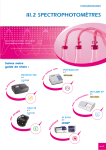
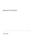
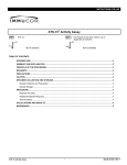
UVIKON XL
UVIKON XS
Operating manual
Manual version: 5.0
UVIKON XL/XS
INDEX
SECTION
GENERAL INFORMATION
SECTION 2
INSTRUMENT DESCRIPTION
SECTION 3
INSTALLATION
SECTION 4
OPERATING INSTRUCTIONS
SECTION 5
MAINTENANCE
SECTION 6
OPTIONS AND ACCESSORIES
SECTION 7
APPENDIX
-3-
UVIKON XL/XS
SUMMARY
1. GENERAL INFORMATION.................................................................... 8
1.1.
GENERAL WARNINGS....................................................................................... 8
1.2.
DESCRIPTION OF SYMBOLS ............................................................................ 9
1.3.
QUALITY, RELIABILITY AND SAFETY ............................................................... 9
1.4.
YOUR LOCAL CONTACT FOR SALES AND SERVICE OF SCHOTT
INSTRUMENTS PRODUCTS........................................................................................ 10
1.5.
PRINTING HISTORY......................................................................................... 11
1.6.
UPDATING LIST ............................................................................................... 11
2. INSTRUMENT DESCRIPTION............................................................. 16
2.1.
GENERAL POINTS ........................................................................................... 16
2.2.
SPECIFICATIONS............................................................................................. 17
2.3.
SYSTEM CONCEPT ......................................................................................... 18
2.3.1. Display......................................................................................................... 18
2.3.2. Electronics ................................................................................................... 18
2.3.3. Optics .......................................................................................................... 18
3. INSTALLATION ................................................................................... 22
3.1.
UNPACKING AND INSTRUMENT SETUP........................................................ 22
3.1.1. Unpacking ................................................................................................... 22
3.1.2. Checking the serial number of the instrument ............................................. 23
3.2.
INSTALLING THE INSTRUMENT ..................................................................... 24
3.2.1. Environmental conditions ............................................................................ 24
3.3.
INITIAL INSTALLATION .................................................................................... 25
3.3.1. Connection to the mains supply .................................................................. 25
3.3.2. Connection to the Personal Computer......................................................... 25
3.3.2.1. PC minimum requirements.....................................................................................25
3.3.3. Software Installation, LabPower .................................................................. 25
4. OPERATING INSTRUCTIONS ............................................................ 28
5. MAINTENANCE ................................................................................... 30
5.1.
DECONTAMINATION ....................................................................................... 30
5.1.1. Requirements .............................................................................................. 30
5.1.2. Risks............................................................................................................ 30
5.2.
CLEANING THE INSTRUMENT ........................................................................ 31
5.3.
VOLTAGE AND FUSES .................................................................................... 31
6. OPTIONS AND ACCESSORIES.......................................................... 34
6.1.
INTERNAL ACCESSORIES .............................................................................. 34
-5-
UVIKON XL/XS
6.2.
EXTERNAL ACCESSORIES............................................................................. 36
6.3.
ACCESSORY CONFIGURATIONS................................................................... 36
7. APPENDIX ........................................................................................... 38
7.1.
SERVICE CENTERS......................................................................................... 38
-6-
UVIKON XL/XS
SECTION 1
GENERAL INFORMATION
-7-
UVIKON XL/XS
1. GENERAL INFORMATION
The user should, before using this equipment, have read and understood this operating
manual, particularly the general warnings given below
1.1. GENERAL WARNINGS
Always disconnect the mains plug before starting any work inside the
instrument
Any maintenance operation inside the instrument, including lamp
replacement, must be carried out by a service engineer or trained
personnel authorised by SCHOTT INSTRUMENTS. The user is permitted
access only to the inside of the sample compartment
Keep the sample compartment clean
The Deuterium lamp used in this unit emits UV radiation
It is important that where the equipment and accessories can come into
contact with human or animal tissues or fluids (particularly blood),
they should always be regarded as contaminated and potentially
hazardous (See Section 5 for decontamination)
HANDLE
NOT FOR CARRYING
HANDLE
NOT FOR CARRYING
-8-
UVIKON XL/XS
1.2. DESCRIPTION OF SYMBOLS
Caution (refer to enclosed documents). In the lamp
compartment, it indicates the presence of high temperature and
ozone generated by the Deuterium lamp.
Power on
Power off
AC (alternating current)
Protective earth conductor terminal
Caution, risk of electric shock
1.3. QUALITY, RELIABILITY AND SAFETY
This equipment has been designed with emphasis on QUALITY, RELIABILITY and
SAFETY. SCHOTT INSTRUMENTS will accept responsibility for these aspects only if the
following conditions are met:
a)
All electrical installations in the room or building in which the equipment is to
be used must comply with regulations specified in the country where the
equipment is to be used.
b)
The equipment must be used in accordance with the instructions for use
provided by SCHOTT INSTRUMENTS.
c)
All modifications and repairs to the equipment must be carried out by
authorised SCHOTT INSTRUMENTS persons, their Agents or authorised
Technicians.
d)
Modifications must not be carried out unless they conform to approved
Engineering Service Information issued according to the appropriate SCHOTT
INSTRUMENTS procedure.
e)
The equipment installation must be carried out in accordance with local
requirements for responsibility and warranty.
NOTE:
Routine tests
Routine test are performed on 100% of the produced equipment according to
the requirements specified in Annex K of the Safety Standard EN 610101+A2: + Dev. UL/CSA
-9-
UVIKON XL/XS
1.4. YOUR LOCAL
CONTACT FOR
SALES AND SERVICE OF
SCHOTT INSTRUMENTS
PRODUCTS
TO BE ENTERED BY LOCAL COMPANY OR
AGENT
- 10 -
UVIKON XL/XS
1.5. PRINTING HISTORY
Issue
This is a new reprint of the complete publication. A new issue does not feature
necessarily new information with respect to the last version.
Date and level of an update refers to the replacement of some pages concerned in a
product change.
Issue Date/Level
Update Date/Level
September 1999/1
February 2000/2
May 2000/3
September 2000/4
July 2002/5
Pages effectively updated:
Owing either to a change of contents or to a new text paging-up.
These pages are identified by a black box positioned on the left side of the page number.
This box will be removed at the first release of a new issue.
Issue or Update
Date/Level
Pages updated
February 2000/2
All
May 2000/3
All
September 2000/4
All
July 2002
All
1.6. UPDATING LIST
See the next sheet.
- 11 -
UVIKON XL/XS
UPDATING
OPERATING MANUAL
UVIKON XL
PUBL. CODE:
70/KP95-90342
ISSUE:
UPDATE:
No. 5
DATE:
July 2002
UPDATING INSTRUCTIONS
To keep the publication constantly up to date, it is advisable to substitute the pages that are out of date with the ones attached.
It is also recommended that the updating list, where the contents of the updating of the Manual is recorded, should also be
inserted immediately after the “Printing history” page at the beginning of the manual.
UPDATING LIST
Section
Issue/Updating
No.
Pages
Replace page(s)
Add the following page(s)
with page(s)
- 12 -
UVIKON XL/XS
S ection
Issue/Updating
No.
Pages
Replace page(s)
Add the following page(s)
with page(s)
- 13 -
UVIKON XL/XS
SECTION 2
INSTRUMENT DESCRIPTION
- 15 -
UVIKON XL/XS
2. INSTRUMENT DESCRIPTION
2.1. GENERAL POINTS
SCHOTT INSTRUMENTS is proud to introduce the newest series of UVIKON ultravioletvisible spectrophotometers: the UVIKON Simplicity Concept with DSP Technology.
The Advanced Digital Signal Processing Technology inside the UVIKON combines its
high-performance true double beam optical design with rapid scanning and powerful yet
intuitive software.
The UVIKON is engineered to make it quick and easy for all to use – regardless of the
analytical method – without sacrificing capabilities.
The UVIKON Xx spectrophotometer is a double beam spectrophotometer, which employs
state of the art technology for collection, presentation, storage and retrieval of analysis
data.
The UVIKON Xx is completely controlled via the RS-232 interface by an external personal
computer.
The UVIKON Xx software, provided with the spectrophotometer, runs under Windows NT
operating software.
Light sources
Deuterium and tungsten-halogen lamps
Monochromator
High energy low stray light diffraction grating with 1300
lines/mm, 175mm focal length.
Detector
R955 Photomultiplier
Photodide
Dimensions
W 680 mm x D 565 mm x H 275 mm
Weight
35 Kg net
Mains Voltage
100 - 240VAC ±10%
Power
200VA
Frequency
50 - 60 Hz
- 16 -
(Uvikon XL)
(Uvikon XS)
UVIKON XL/XS
2.2. SPECIFICATIONS
UVIKON Xx is a double beam high performance spectrophotometer with the following
specifications:
UVIKON XL
UVIKON XS
Wavelength range
180-900 nm
190-1100 nm
Wavelength step
0.05-10 nm
0.05-10 nm
Spectral bandwidth
0.2 - 0.5 – 1 – 2 - 4 nm;
0.5– 1–2- 4 (reduced height)
1.8 fixed
Scan speed
10-5000 nm/min
10-2000 nm/min
Transfer speed
7000 nm/min
5000 nm/min
Wavelength accuracy
Holmium peaks,
10nm/min, 0.05nm step
± 0.25 nm
± 0.3 nm
Wavelength precision
Holmium Oxide filter shoulder
± 0.025 nm
± 0.03 nm
Baseline flatness
200-800nm, 2nm, 200nm/min
≤ ±1mAbs
≤ ±1mAbs
Stray light
NaI, 220nm, 1nm Bw,
≤ 0.015 %T
≤ 0.03 %T
Linearity
0-3.3 Abs
0-3.0 Abs
Photometric range
± 5 Abs
± 3.5 Abs
Photometric accuracy
1Abs NIST, 1sec, 590nm
± 3 mAbs
± 3 mAbs
Photometric precision
1Abs NIST, 1sec, 590nm
± 0.5 mAbs
± 0.5 mAbs
Noise RMS
0Abs, 500-600nm, 2nm, 1sec
40 µAbs
30 µAbs
Drift
580nm, 2nm, 1 sec - warm-up 2 hour
0.1 mAbs/h
0.1 mAbs/h
Response time
0.02-5 sec
0.02-5 sec
1sec, 2nm, r² = 0.999 (250nm)
- 17 -
UVIKON XL/XS
2.3. SYSTEM CONCEPT
UVIKON Xx is a double beam high performance spectrophotometer controlled from an
external PC running under MS Windows NT.
The communication between PC and spectrophotometer is via a standard RS232
connection
Minimum system requirements to run the UVIKON SW see section 3; as minimum a 17
inch monitor is suggested.
2.3.1.
Display
Below is the layout of the UVIKON XL status display with the description of the
symbols.
System failure
Measure
Halogen lamp
Deuterium lamp
Power on
SYSTEM FAILURE:
MEASURE:
HALOGEN LAMP:
DEUTERIUM LAMP:
POWER ON
2.3.2.
Red light indicates a system error
Green light shows that UVIKON XL is measuring
Green lamp indicates halogen lamp on
Green light indicates Deuterium lamp on or igniting
Green light indicates system power is on
Electronics
Data processing is executed using single channel analog electronics with 20 bit
A/D converter and DSP processor. High speed microcontrollers control the
photometer drive and the communication with PC. Firmware is stored in Flash
memory and can be upgraded by PC download.
2.3.3.
Optics
The basic optical conceptis as follows:
- 18 -
UVIKON XL/XS
Light is provided by D2 and Halogen lamps with a switching mirror and single
monochromator. The beam is split by a rotating chopper wheel which reflects
light via a set of mirrors onto either a photomutiplier detector (XL) or photodide
(XS).
- 19 -
UVIKON XL/XS
SECTION 3
INSTALLATION
- 21 -
UVIKON XL/XS
3. INSTALLATION
3.1. UNPACKING AND INSTRUMENT SETUP
3.1.1.
Unpacking
The UVIKON Xx is contained in one single packing case. Open the case, lift the
instrument out of the box and place it on a table.
The instrument is heavy, do not lift alone. Have at least one other
person help whenever lifting or moving the instrument.
Most of the accessories are contained in a separate enclosure.
Please make sure that you have removed these before storing the
box, do not discard.
HANDLE
NOT FOR CARRYING !
HANDLE
NOT FOR CARRYING !
Allow suitable space for connecting and disconnecting the power
cable and switching the instrument on/off.
Check the consignment against the shipping list. If any parts are
damaged, please inform your local SCHOTT INSTRUMENTS
representative immediately.
- 22 -
UVIKON XL/XS
NOTE:
Use only the original packing case to return the unit to the factory for
any reason.
The UVIKON XS software package includes:
LAB POWER
APPLICATIONS
LAB POWER
VALIDATION
DNA/RNA Purity Check -
Set up program
Set up program
Software User Manual
Software User Manual
Software User Manual
The UVIKON XL software package includes:
UV Vision or UV Vision pharma
3.1.2.
Setup program and manual
Checking the serial number of the instrument
The plate showing the serial number is mounted to the rear right hand side of the
instrument. This number must be identical with the serial number on the delivery
note. Should this not be the case please inform the local SCHOTT
INSTRUMENTS representative immediately.
RS232 - PC connection
Mains plug
- 23 -
UVIKON XL/XS
3.2. INSTALLING THE INSTRUMENT
3.2.1.
Environmental conditions
Performance and safety of the equipment are guaranteed only if it is operated
under the following environmental conditions:
The instrument is designed for internal use and altitude below 2000 metres
Installation category II with smaller transient over-voltages (IEC 664)
Pollution degree 2 (CEI EN 61001-1)
Room temperature between 15°C (59°F) and 35°C (95°F)
In locations where the relative humidity is lower than 80%
The UVIKON Xx contains many sensitive optical components, to obtain optimum
performance avoid using this instruments under the following conditions:
In locations subjected to dust or vapours of solvents and acids
In locations prone to vibrations
On an unstable or uneven surface
Near appliances generating strong magnetic fields
- 24 -
UVIKON XL/XS
3.3. INITIAL INSTALLATION
It is most important that there is sufficient free space around the instrument for
adequate ventilation (10cm).
3.3.1.
Connection to the mains supply
Mains voltages is automatically adjusted in the range from 100 to 240V
Frequency adjustment for 50/60Hz is not necessary.
WARNING
The outlet must have a protective earth connection.
The main switch is located in the lower left side of the equipment
3.3.2.
Connection to the Personal Computer
Use PC COM1 for the connection of the spectrophotometer serial cable and
COM2 for external UVIKON XL accessories (see section 6). Connect the serial
cable between UVIKON Xx 9 poles DIN connector located on the rear right hand
side and PC serial port.
Baud rate must be set to 38400 bit/sec
NOTE:
Use only equipment, e.g. PC, monitor, keyboard etc., which
comply with the standard EN60950
Refer to the specific documentation for hardware connection and software
installation
3.3.2.1.
PC minimum requirements
CPU:
RAM:
Hard Disk
CD ROM drive
3.3.3.
300 MHz
64 MB
2 GB
Software Installation, LabPower
1. Insert the CD-ROM
2. Select Run from the Start menu
3. Select the Set up program from the CD_ROM Lab Power directory
4. Press OK to start the Set up program
5. Follow the on-screen instructions
- 25 -
UVIKON XL/XS
SECTION 4
OPERATING INSTRUCTIONS
- 27 -
UVIKON XL/XS
4. OPERATING INSTRUCTIONS
Verify the proper connection of the spectrophotometer and PC via RS232 cable serial
cable, part number SZ 1430 (scopy of delivery)
Use PC COM1 for the connection of the spectrophotometer serial cable and COM2 for
external UVIKON Xx accessories (see section 6).
Switch on the spectrophotometer and the PC.
Launch Windows 2000/XP and press the corresponding LAB POWER icon in order to
load the UVIKON spectrophotometer software.
If the communication is not active the sequence of messages will finish with:
Connect: Service terminated with error
In case of this message check that:
•
•
the spectrophotometer is on;
for correct connection between spectrophotometer and PC.
Also verify in the UVIKON SW communication window that:
•
•
serial port = COM1
baud rate = 38400
- 28 -
UVIKON XL/XS
SECTION 5
MAINTENANCE
- 29 -
UVIKON XL/XS
5. MAINTENANCE
WARNING
Any maintenance operation inside the instrument, including the lamp
replacement, must be carried out by a specialised service engineer
authorised by SCHOTT INSTRUMENTS
The user is permitted access only to the inside of the sample compartment.
Your UVIKON Xx has been constructed using precision components and will require very little
daily maintenance other than keeping the unit clean.
5.1. DECONTAMINATION
5.1.1.
Requirements
Due to the nature and seriousness of diseases such as the Human
Immunodeficiency Virus (HIV) and Hepatitis B, it is important that, where
equipment and accessories can come into contact with human or animal tissues
or fluids (particularly blood), they should always be regarded as contaminated
and potentially hazardous.
Contaminated equipment and accessories must be decontaminated using the
hospital decontamination and disinfecting procedures appropriate for the device.
Decontamination must be carried out by properly trained staff.
If you have any doubt regarding contamination or decontamination, consult your
local infection control officer.
5.1.2.
Risks
All human or animal tissues or fluids in the hospital and laboratory environment
are capable of transmitting infection. Therefore, special precautions must be
taken in hospitals and laboratories that deal with patients who have highly
infectious disease.
Infection can occur by the following routes:
Through broken skin;
Needles or other sharp objects;
Contamination of cuts, abrasions or burns;
Ingestion (placing a contaminated object in
or near the mouth, e.g. pen, finger);
Direct contact with mucous membranes (e.g. eyes);
Inhalation of contaminated dust or aerosols.
- 30 -
UVIKON XL/XS
5.2. CLEANING THE INSTRUMENT
The sample compartment windows are not accessible from inside the sample
compartment. Keep the sample compartment clean.
To clean the instrument and the sample compartment use only a dry or
water/neutral detergent wet cloth, do not use organic solvents or abrasive agents.
Do not use solvents, e.g. acetone, to clean the instrument.
5.3. VOLTAGE AND FUSES
The unit is equipped with a wide range power supply capable to operate from 80 to 240
VAC 50/60 Hz without any voltage selection adjustment.
Fuses are located into the main plug socket, to check or change proceed as follows:
•
Unplug mains cable
•
Pull out the fuse holder (helping with the aid of a small flat screwdriver)
•
Insert the correct fuses (2 time lag fuses T3.15A - 250V, 5mm by 20mm)
•
Push the fuse holder back into position
- 31 -
UVIKON XL/XS
SECTION 6
OPTIONS AND ACCESSORIES
- 33 -
UVIKON XL/XS
6. OPTIONS AND ACCESSORIES
6.1. INTERNAL ACCESSORIES
Accessories driven by the spectrophotometer to be connected to the mechanical and
electrical connections in the sample compartment.
SZ 1160
The integrating sphere is designed for measuring the transmittance of
very turbid or colloidal solutions either in liquid or solid form, highly light
scattering solid samples, the colour of solid samples and the diffuse or
specular reflectance of solid samples.
SZ 1030
QuickLock cell holder for 10 mm cells, thermostattable. Supplied as
standard with the instrument.
SZ 1060
QuickLock cell holder for 10/20 mm cells, thermostattable.
SZ 1080
QuickLock long path rectangular cell holder 10 to 100 mm path length.
SZ 1090
QuickLock cylindrical cell holder
SZ 1040
Magnetic stirrer accessory, for stirring of reference and sample. The
speed is variable. Supplied with 5 Teflon-coated bars (8x3 mm). To be
used with SZ 1030.
SZ 1050
Teflon-coated magnetic bars, set of 5 bars (8x3 mm).
SZ 1140
The automatic sipper system is based on a peristaltic pump. Different tube
materials can be used.
Includes thermostatting fluid connection block and tube set.
It can be directly connected to the Thermopack or an external circulating
water bath.
SZ 1130
Temperature sensor for cell content. Miniaturised sensor with inert glass
body to measure the temperature within the cell. A special protective
holder is supplied, which can be fixed in the sample compartment.
SZ 1120
Temperature sensor for holder. Measures the temperature of the cell
holders.
SZ 1110
QuickLock automatic 6+6 cell changer. Two independently driven cell
holders allow the measurement of up to 10 kinetic samples in one run.
Thermostattable cell holders and unique climate chamber for best
temperature distribution are included.
Requires connection to an external circulating water bath, includes
thermostatting fluid connection block.
SZ 1330
Standard flow cell 160 µL. This cell is used together with the Quick Lock
automatic sipper for 10 mm cells. The flow cell has an internal volume of
160 µL. Other flow cells can be used.
- 34 -
UVIKON XL/XS
Flow cell, 80µL, 10 mm path
Open microcells, 4 mm inner width, 10 mm path, set of 2
Stoppered microcells, 4 mm inner width, 10 mm path, set of 2
Open microcells, 2 mm inner width, 10 mm path, set of 2
Stoppered microcells, 2 mm inner width, 10 mm path, set of 2
Open rectangular cells, 10 mm path, set of 2
Open rectangular cells, 10 mm path, set of 4
Stoppered rectangular cells, 10 mm path, set of 2
Stoppered rectangular cells, 10 mm path, set of 4
The following picture shows the connectors of the internal accessories in the sample compartment.
Cell Changer - Sipper
Temperature sensor
Stirrer
RS232 optional
- 35 -
UVIKON XL/XS
6.2. EXTERNAL ACCESSORIES
Accessories with an external controller to be driven by the PC via RS232 COM2.
SZ 1036
SZ 1035
The thermopack accessory can be used to control the temperature of all
thermostattable cell holders and of the cell changer. The fluid circulated is
thermostatted via Peltier effect.
The THERMOSYSTEM consists of a quick lock automatic 6+6 Cell
Changer with Peltier effect thermostatting system and magnetic stirring
capability.
The Thermo System must be connected to an external liquid circuit for
cooling of the Peltier elements.
6.3. ACCESSORY CONFIGURATIONS
QuickLock cell holder for 10 mm cells
The drawing overleaf shows all available options, which can be used together with the
standard cell holder. The holder is shown with the tube set and the thermostatting fluid
connection block (70/91-00610), which are used for external SZ 1070 temperature
control.
Temperature sensor for holder (70/91-00607)
This sensor measures the temperature of the sample or reference cell holder. The sensor
fits into a threaded hole in the cell holder. This sensor can be used together with the
magnetic stirrer (70/91-00580).
Temperature sensor for cell content (70/91-00608)
This sensor measures the sample temperature in a standard 10 mm cell. This sensor
can be used together with the magnetic stirrer (SZ 1040).
Magnetic stirrer accessory (SZ 1040)
The magnetic stirrer accessory fits into the base of the cell holder. It can be used together
with any external temperature control system, the temperature sensor for cell content (SZ
1130) and the temperature sensor for holder (SZ 1120).
Water bath and thermopack.
We recommend use of the thermostatting fluid connection block and the tube set should
an external water bath be employed for temperature control of the cell holder.
QuickLock automatic 6+6 cell changer
Temperature sensor for cell content (SZ 1130)
This sensor measures the temperature of a sample contained in a standard 10 mm cell in
any one of the 12 sample positions of the cell changer. It cannot be used for external
temperature control but is very useful for monitoring the actual sample temperature. The
tubes of an external circulating water bath can be directly connected to the fluid
connection block of the cell changer.
- 36 -
UVIKON XL/XS
SECTION 7
APPENDIX
- 37 -
UVIKON XL/XS
7. APPENDIX
7.1. SERVICE CENTERS
SCHOTT INSTRUMENTS
Hattenbergstraße 10
D-55122 Mainz
GERMANY
Phone. : +49 6131 66 5111
Fax : +49 6131 66 5111
E-mail : [email protected]
- 38 -