1
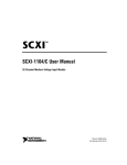
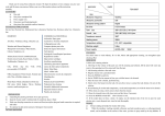
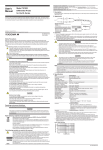
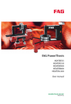
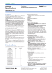
Model 701974
PBL5000
5 GHz Low Capacitance Probe(10:1/20:1)
User’s
Manual
Safety Precautions
Please heed the following warnings when handling the probe. Yokogawa bears no responsibility for, nor
implies any warranty against damages occurring as a result of failure to take these precautions. Please
read the user’s manual of the measuring instrument and fully understand the specifications and handling
procedures of that instrument before using the probe.
• The following safety symbols and words are used in this manual.
This symbol warns against danger to personnel and instruments, and indicates that the
user should refer to the relevant instructions in the user’s manual.
WARNING
Calls attention to actions or conditions that could cause serious injury or death to the user,
and precautions that can be taken to prevent such occurrences.
CAUTION
Calls attentions to actions or conditions that could cause light injury to the user or damage
to the instrument or user’s data, and precautions that can be taken to prevent such
occurrences.
• The following precautions must be taken to prevent electric shock and other potentially fatal accidents
and damage to instruments.
WARNING • Ground the Measuring Instrument
Always connect the main instrument’s protective grounding.
• Connect the Probe’s Earth Wire
Connect the earth wire (ground potential) to ground.
• Take Care When Connecting to the Item under Test
Take care to avoid electric shock when connecting the probe to the item under test. Also, never
disconnect the probe from the measuring instrument while the probe is connected to the circuit under
test.
• Never Use the Probe If You Suspect It Is Damaged
If you suspect the probe might be damaged, please consult with your Yokogawa dealer or
representative.
• Maintain Nondestructive Input Voltages
Do not apply a voltage exceeding the nondestructive input voltage between input and ground.
• Check the Grounding
Before connecting the probe input terminal to the item under test, check that the measuring instrument
is properly grounded, that the probe output connector is connected to the BNC connector of the
instrument, and that the earth lead is correctly connected to ground.
• Do Not Use the Probe in Humid Locations
To avoid electric shock, never use the probe in areas of high humidity.
• Do Not Use the Probe Near Flammable Gases
To avoid injury and fire, do not use the probe near flammable or explosive gasses or vapors.
• Avoid Exposed Circuits
To prevent injury, remove all jewelry such as rings and wristwatches. When the power is ON, do not
touch any exposed connectors or components.
• Handle the Probe Safely
Do not touch the probe input terminal with your hands. Also, never touch the probe with wet hands.
CAUTION
• Maximum Input Voltage
Do not apply a voltage exceeding the maximum voltage to the probe’s input terminal.
Overview
The model 701974 PBL5000 5 GHz Low Capacitance Probe is a low input capacitance passive probe (attenuation ratios of 1/10 or 1/20) for use with oscilloscopes having an input impedance of 50 Ω. The attenuation ratio
can be changed by replacing the resistor on the probe tip.
Components
As shown in the figure below, the probe consists of the probe itself, and standard accessories.
3
5
2
4
1
1
Probe head
–
2
450 Ω resistors (2 pcs)
B8099FE
3
950 Ω resistors (2 pcs)
B8099FF
4
Probe cable
–
5
SMA(J)-BNC(P) conversion adapter –
Specifications
Item
Standard Operating
Environment
System Requirements
Specifications
Temperature: 23°C ±5°C
Humidity:
55% ±10% RH (no condensation)
Temperature: 5°C to 40°C
Humidity:
20% to 80% RH (no condensation)
Storage Environment
Temperature: –20°C to 60°C
Humidity:
20% to 80% RH (no condensation)
Total length of probe
Approximately 1.1 m
Connector type
SMA
Input resistor*1
Within ±2% of 450 Ω
Within ±2% of 950 Ω
Input capacitance
450 Ω: 0.25 pF (Typical*2)
950 Ω: 0.4 pF (Typical*2)
Attenuation ratio*3
Within ±3.5% of 10:1
Within ±3.5% of 20:1
Frequency bandwidth*4
DC to 5 GHz (–3 dB or more)
Rise time*4
70 ps or less (Typical*2)
Maximum input voltage
20 Vrms, 40 VACpeak
Nondestructive input voltage 20 Vrms, 40 VACpeak
*1: When no load is present. Standard operating environment.
*2: Typical value represents a typical or average value. It is not strictly guaranteed.
*3: In combination with an oscilloscope having an input resistance of 50 Ω. Standard operating environment.
*4: When the distance between probe tip and ground is 9 mm. Standard operating environment.
Operating Procedure
The resistors are extremely easy to bend. Always use the resistor cover on the probe tip.
Connect the probe to an oscilloscope having an input impedance of 50 Ω. When connecting instruments with a BNC
connector input, use the accessory SMA(J)-BNC(P) adapter.
Use a soft cloth to wipe away dirt, and be careful not to damage the probe. Also, never dip the instrument in liquid, nor
use any detergents or abrasives. Do not use any volatile solvents such as benzine.
Note
• Calibration of this instrument is not guaranteed. No test certificate is available.
• Bringing the probe near transformers, circuits with large currents, wireless devices, or other objects emitting.
YOKOGAWA ELECTRIC CORPORATION, Communication & Measurement Business Headquarters
Phone: (81)-422-52-6768, Fax: (81)-422-52-6624, E-mail: [email protected]
YOKOGAWA CORPORATION OF AMERICA
YOKOGAWA EUROPE B.V.
Phone: (1)-301-916-0409, Fax: (1)-301-916-1498
Phone: (31)-33-4641858, Fax: (31)-33-4641859
All Rights Reserved, Copyright © 2005,
Yokogawa Electric Corporation
2nd Edition : May 2006
YOKOGAWA ENGINEERING ASIA PTE. LTD.
Phone: (65)-62419933, Fax: (65)-62412606
IM 701974-01E
2nd Edition